Makita DS4010 - Manual
Makita DS4010 Impact Driver – Manual, read for free online in PDF format. We hope this helps you resolve any issues you may have. If you have further questions, please contact us through the contact form.


Table of Contents:
- Page 2 – epair; Note
- Page 3 – clockwise
- Page 5 – counterclockwise
- Page 6 – ircuit diagram; black; without variable speed control
Output
S
tandard equipment
Note:
The standard equipment for the tool shown above may vary by country.
Chuck key S-13 ........... 1 (for DS4010, DS4011)
Chuck key S-16 ........... 1 (for DS5000)
Side grip ...................... 1
Plastic carrying case .... 1 (for DS4011, if requested)
O
ptional accessories
Depth gauge
Keyless Drill chuck set (for DS4010, DS4011)
Keyed drill chuck set (for DS4010, DS4011)
Bits
Hole saws
Wrench 9 (for Hole saw)
Angle attachment
Wrench 17 (for Angle attachment)
S
pecification
Continuous Rating (W)
Voltage (V)
Cycle (Hz)
Input
Max. Output (W)
110
120
220
230
240
7.2
6.5
3.6
3.4
3.3
50/ 60
50/ 60
50/ 60
50/ 60
50/ 60
750
---
750
750
750
380
380
380
380
380
540
650
650
650
650
Current (A)
110
120
220
230
240
7.2
6.5
3.6
3.4
3.3
50/ 60
50/ 60
50/ 60
50/ 60
50/ 60
750
---
750
750
750
350
350
350
350
350
550
550
550
550
550
DS4010
DS4011, DS5000
Model No.
Description
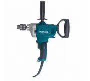
PRODUCT
C
ONCEPT AND MAIN APPLICATIONS
P 1/
8
DS4010, DS4011/
DS5000
Drills 13mm (1/2")/ 16mm (5/8'')
Dimensions: mm (")
Width (W)
Height (H)
Length (L)
Model No.
DS4010
DS4011
DS5000
83 (3-1/4)
391 (15-3/8)
340 (13-3/8)
348 (13-3/4)
401 (15-3/4)
Drill chuck type
Chuck capacity: mm (")
Double insulation
Net weight
*2
: kg (lbs)
Power supply cord
*1
: m (ft)
No load speed: min-
1
= rpm
Specification
Model No.
DS4010
DS4011
DS5000
2 - 13
(1/16 - 1/2)
2 - 13
(1/16 - 1/2)
3 - 16
(1/8 - 5/8)
0 - 600
600
600
Yes
No
Yes
No
Yes
Yes
No
Yes
Yes
2.8 (6.2)
2.8 (6.3)
3.0 (6.6)
2.5 (8.2)
2.5 (8.2)
2.5 (8.2)
*1
2.0m (6.6ft) for Brazil, Australia
*2
Weight according to EPTA-Procedure 01/2003, with Side grip
13 (1/2)
36 (1-7/16)
13 (1/2)
36 (1-7/16)
16 (5/8)
36 (1-7/16)
Reverse function
Capacities: mm (")
Steel
Wood
Keyed
Keyed
Keyed
Variable speed control by trigger
These three drills are redesigned version of models 6013B, 6013BR, 6016BR
with the same high performance as the current models.
Their main features and benefits are:
Switch type is the main notable specification difference between
these three models:
DS4010
Trigger type, without reverse function, with variable speed control
DS4011, DS5000
Rocker type, with reverse function, without variable speed control
Non-skid elastomer covering main handle area for good looking impression
and sure and comfortable grip
Full 360 degree rotatable D-handle with 24 positive stops
for multi-position operation
T
ECHNICAL INFORMATION
L
H
W
DS4010 is also available without Drill chuck as model DS4010M.
"Loading the manual" means you need to wait until the file loads and becomes available for online reading. Some manuals are very large, and the time they take to appear depends on your internet speed.
Was this manual helpful?
About this manual
- Brand
- Makita
- Model
- DS4010
- Document type
- Manual
- Category
- Impact Driver
- Language(s)
- English
- Pages
- 8
- File size
- 2.5 MB
- Format
Summary
P 2 / 8 R epair CAUTION: Repair the machine in accordance with “Instruction manual” or “Safety instructions”. [1] NECESSARY REPAIRING TOOLS [2] LUBRICATIONS Fig. 1 Code No. Description Use for 1R139 Drill chuck extractor Removing / Assembling Drill chuck 1R223 Torque wrench shaft 20-90 N.m Removing ...
P 3 / 8 R epair [3]-2. Drill chuck, Gear, Spindle Fig. 4 Fig. 6 1R139 2. Fit the flats of Spindle to the notch of 1R139 and then hold 1R139 in vise. 3. Attach 1R224 and 1R298 to 1R223 and then secure 1R298 with Drill chuck. 4. Turn 1R223 counterclockwise. 1. Hold Drill chuck in vise. 2. Fit the flat...
P 5 / 8 R epair (1) Assemble Gear section as illustrated in Figs. 10 and 11 . [3] DISASSEMBLY/ASSEMBLY [3]-2. Gear, Spindle Fig. 10 Fig. 9 4. Set Pin 3 in place to assemble Gasket and Gear housing cover complete precisely to Gear housing complete in the next step. 5. Align the holes of Gasket and th...
Ask a question
Related manuals
Popular Makita Impact Drivers
More Makita Impact Drivers models
 Makita DHP481Z User Manual
 Makita DHP482RMJ User Manual
 Makita DHP484RFE User Manual
 Makita DHP486RTJ User Manual
 Makita DHP487Z User Manual
 Makita DP2011 User Manual
 Makita DT03R1 User Manual
 Makita DTD153Z User Manual
 Makita DTD154Z User Manual
 Makita DTD157RTJ User Manual
 Makita DTD157Z User Manual
 Makita DTD170Z User Manual
 Makita DTD172Z User Manual
 Makita DTS141Z User Manual
 Makita FS2300 User Manual
 Makita FS2700 User Manual
 Makita FS4000 Manual
 Makita FS4200 Manual
 Makita FS4300 Manual