Ikea IMH160DW1 - Installation Manual
Ikea IMH160DW1 – Installation Manual, read for free online in PDF format. We hope this helps you resolve any issues you may have. If you have further questions, please contact us through the contact form.


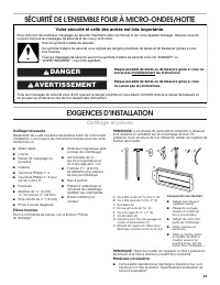
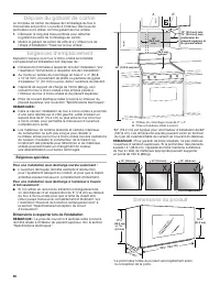
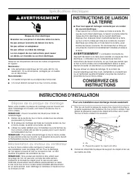
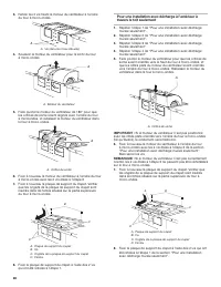
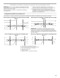
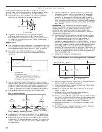
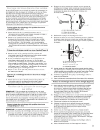
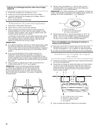
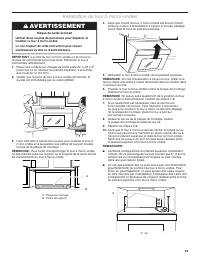
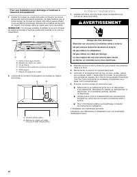
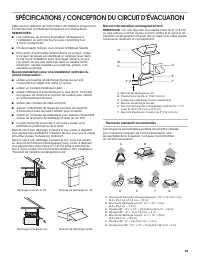
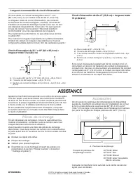
Table of Contents:
- Page 2 – INSTALLATION REQUIREMENTS; Tools Needed; MICROWAVE HOOD COMBINATION SAFETY; Your safety and the safety of others are very important.; DANGER; Tools and Parts
- Page 3 – Special Requirements; Product Dimensions; Installation Dimensions
- Page 4 – INSTALLATION INSTRUCTIONS; Remove Mounting Plate; Wall Venting Installation Only; Electrical Requirements; WARNING; GROUNDING INSTRUCTIONS
- Page 5 – Roof Venting Installation Only
- Page 6 – No Wall Studs at End Holes; Wall Stud at End Hole; Wall Studs at End Holes
- Page 7 – Mark Rear Wall; Drill Holes in Rear Wall; Installation for No Wall Studs at End Holes
- Page 8 – Installation for Wall Studs at Both End Holes (Figure 4); Attach Mounting Plate to Wall; No Wall Studs at End Holes (Figures 1 and 2); Prepare Upper Cabinet
- Page 9 – For Roof Venting Installation Only; Install Damper Assembly
- Page 10 – Complete Installation
- Page 11 – VENTING DESIGN SPECIFICATIONS; For optimal venting installation, we recommend:; Rectangular to Round Transition; Recommended Standard Fittings
- Page 12 – Recommended Vent Length; ASSISTANCE; Replacement Parts
- Page 13 – REQUISITOS DE INSTALACIÓN; Herramientas necesarias; SEGURIDAD DE LA COMBINACIÓN MICROONDAS CAMPANA; Su seguridad y la seguridad de los demás es muy importante.; ADVERTENCIA; Piezas y herramientas
- Page 14 – Requisitos especiales; Dimensiones del producto; Dimensiones de instalación
- Page 15 – INSTRUCCIONES DE INSTALACIÓN; Retire la placa de montaje; Solamente para la instalación con ventilación en la pared; Requisitos eléctricos; INSTRUCCIONES PARA
- Page 16 – Solamente para la instalación con ventilación en el techo
- Page 17 – Sin pies derechos de pared en los orificios de los extremos; Pie derecho de pared en un orificio del extremo; Pies derechos de pared en ambos orificios de los extremos
- Page 18 – Marque la pared posterior
- Page 19 – Taladre orificios en la pared posterior; Instalación sin pies derechos de pared en los orificios; Ajuste la placa de montaje a la pared; Sin pies derechos de pared en los orificios de los
- Page 20 – Pies derechos de pared en ambos orificios de los; Preparación del armario superior; Instale el ensamblaje de la; (solamente para la ventilación a través
- Page 21 – Instalación del horno de microondas
- Page 22 – Complete la instalación
- Page 23 – ESPECIFICACIONES PARA EL DISEÑO DE LA VENTILACIÓN; Para una instalación con ventilación óptima,; Tubo de ajuste rectangular a redondo; Accesorios corrientes recomendados
- Page 24 – ASISTENCIA; Refacciones
- Page 25 – EXIGENCES D’INSTALLATION; Outillage et pièces; Outillage nécessaire; SÉCURITÉ DE L’ENSEMBLE FOUR À MICRO-ONDES/HOTTE; Votre sécurité et celle des autres est très importante.; AVERTISSEMENT; Pièces fournies
- Page 26 – Dépose du gabarit de carton; Exigences spéciales; Dimensions à respecter lors de l’installation; Dimensions du produit
- Page 27 – Spécifications électriques; INSTRUCTIONS DE LIAISON; INSTRUCTIONS D’INSTALLATION; Dépose de la plaque de montage; Pour une installation avec décharge murale seulement
- Page 28 – Pour une installation avec décharge à l’extérieur à
- Page 29 – Aucun poteau du colombage à la position des trous d’angle; Un trou d’angle face à un poteau du colombage mural; Deux trous d’angle face à des poteaux du colombage mural
- Page 30 – Pour une installation avec décharge murale seulement:; Tracé sur le mur arrière
- Page 31 – Perçage de trous dans le mur arrière; Fixation de la plaque de montage; Aucun poteau du colombage à la position des trous; Poteau du colombage mural à un trou d’angle (Figure 3)
- Page 32 – Poteaux du colombage mural aux deux trous d’angle; Préparation du placard supérieur; Installation du module du clapet; (pour décharge à travers le mur uniquement)
- Page 33 – Installation du four à micro-ondes
- Page 34 – Achever l’installation
- Page 35 – SPÉCIFICATIONS / CONCEPTION DU CIRCUIT D’ÉVACUATION; Recommandations pour une installation optimale du; Raccord de transition rectangulaire/rond
- Page 36 – Longueur recommandée du circuit d’évacuation; Pièces de rechange
MICROWAVE HOOD COMBINATION
INSTALLATION INSTRUCTIONS
This product is suitable for use above electric or gas cooking products up to and including 36" (91.4 cm) wide.
The installation instructions cover different models, so the appearance of your particular model may be different from
the illustration version.
COMBINACIÓN MICROONDAS CAMPANA -
INSTRUCCIONES DE INSTALACIÓN
Esta unidad puede usarse encima de productos para cocción eléctricos o a gas de hasta 36" (91,4 cm) de ancho.
Les instructions d'installation couvrent différents modèles; par conséquent, l'aspect de votre modèle peut être différent de celui
de la version illustrée.
INSTRUCTIONS D’INSTALLATION
DE L’ENSEMBLE FOUR À MICRO-ONDES/HOTTE
Ce produit est conçu pour l’utilisation au-dessus d’appareils de cuisson électriques ou à gaz de 36" (91,4 cm) de largeur ou moins.
Las instrucciones de instalación abarcan varios modelos, por lo que el aspecto de su modelo específico puede diferir del que aparece
en la ilustración.
MICROWAVE HOOD
COMBINATION SAFETY .........................2
INSTALLATION REQUIREMENTS ..........2
Tools and Parts ......................................2
Remove Cardboard Template ...............3
Location Requirements .........................3
Product Dimensions ..............................3
Electrical Requirements ........................4
INSTALLATION INSTRUCTIONS ............4
Remove Mounting Plate ........................4
Rotate Blower Motor .............................4
Locate Wall Stud(s) ...............................6
Mark Rear Wall ......................................7
Drill Holes in Rear Wall ..........................7
Attach Mounting Plate to Wall ..............8
Prepare Upper Cabinet .........................8
Install Damper Assembly ......................9
Install the Microwave Oven ...................9
Complete Installation ............................10
VENTING DESIGN SPECIFICATIONS ....11
ASSISTANCE ...........................................12
Replacement Parts ................................12
Accessories ...........................................12
SEGURIDAD DE LA COMBINACIÓN
MICROONDAS CAMPANA .....................13
REQUISITOS DE INSTALACIÓN ............13
Piezas y herramientas ...........................13
Quite la plantilla de cartón ....................14
Requisitos de ubicación ........................14
Dimensiones del producto ....................14
Requisitos eléctricos .............................15
INSTRUCCIONES DE INSTALACIÓN ....15
Retire la placa de montaje ....................15
Rote el motor del soplador ...................15
Ubique el(los) pie(s) derecho(s)
de pared ................................................17
Marque la pared posterior .....................18
Taladre orificios en la pared posterior ...19
Ajuste la placa de montaje a la pared ...19
Preparación del armario superior .........20
Instale el ensamblaje de la compuerta
de tiro ....................................................20
Instalación del horno de microondas ...21
Complete la instalación .........................22
ESPECIFICACIONES PARA
EL DISEÑO DE LA VENTILACIÓN .........23
ASISTENCIA.............................................24
Refacciones ...........................................24
Accesorios .............................................24
SÉCURITÉ DE L’ENSEMBLE FOUR
À MICRO-ONDES/HOTTE ......................25
EXIGENCES D’INSTALLATION ..............25
Outillage et pièces .................................25
Dépose du gabarit de carton ................26
Exigences d’emplacement ....................26
Dimensions du produit ..........................26
Spécifications électriques .....................27
INSTRUCTIONS D’INSTALLATION ........27
Dépose de la plaque de montage .........27
Réorientation du moteur
du ventilateur .........................................27
Identifier la position du/des poteau(x)
du colombage mural .............................29
Tracé sur le mur arrière .........................30
Perçage de trous dans le mur arrière ...31
Fixation de la plaque de montage
sur lemur ................................................31
Préparation du placard supérieur .........32
Installation du module du clapet
anti-reflux .............................................. 32
Installation du four à micro-ondes ........33
Achever l’installation .............................34
SPÉCIFICATIONS / CONCEPTION
DU CIRCUIT D’ÉVACUATION.................35
ASSISTANCE ...........................................36
Pièces de rechange ...............................36
Accessoires ...........................................36
Table of Contents / Índice / Table des matières
W10823833A
"Loading the manual" means you need to wait until the file loads and becomes available for online reading. Some manuals are very large, and the time they take to appear depends on your internet speed.
Other Manuals for Ikea IMH160DW1
Summary
2 INSTALLATION REQUIREMENTS Tools Needed Gather the required tools and parts before starting installation. Read and follow the instructions provided with any tools listed here. ■ Measuring tape ■ Pencil ■ Masking tape or thumbtacks ■ Scissors ■ No. 2 Phillips screwdriver ■ No. 3 Phillips screwdriver...
3 Remove Cardboard Template The cardboard piece from the top of the microwave oven packaging is perforated. The piece inside the perforation is for use as a rear wall template. 1. Cut along the perforation to separate the template from the rest of the cardboard packaging. 2. Set the cardboard templa...
4 INSTALLATION INSTRUCTIONS Remove Mounting Plate Depending on your model, the mounting plate may be in the foam packaging, or it may be attached to the back of the microwave oven. NOTE: To avoid possible damage to the work surface, cover the work surface. 1. Remove any remaining contents from the m...