IDEAL 61-532 - User Manual

IDEAL 61-532 Measuring Instrument – User Manual, read for free online in PDF format. We hope this helps you resolve any issues you may have. If you have further questions, please contact us through the contact form.


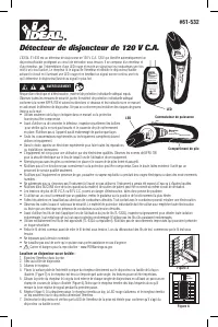


120V AC Circuit Breaker Finder
The IDEAL 61-532 is a 120V AC Circuit Breaker Finder that automatically identifies a circuit breaker/fuse protecting
a live branch circuit. It consists of a transmitter and a receiver. The Transmitter identifies the presence of power
via a red LED and sends a signal over the conductors when connected to an energized circuit. The receiver
reads the transmitter’s signal and identifies the breaker/fuse energizing the circuit by illuminating a red LED
and emitting a continuous beep once it determines the breaker/fuse with the strongest signal.
Arc Flash and Shock Hazard, Proper PPE Required. Follow all safety procedures, wear proper PPE in
accordance to NFPA 70E and follow the guidelines below and the instructions in this manual when
operating the circuit breaker finder. Failure to comply can result in serious injury or death.
• Use only as specified in this manual or protection provided can be compromised.
• Before using, visually inspect to ensure the cases are not cracked and the battery
cover is securely in place. Do not use if there appears to be any damage to the unit.
• Only experienced or technically competent consumers should use this equipment.
When in doubt, call an experienced electrician to make all necessary repairs or
installations.
• The equipment is intended for use by qualified electricians. Follow NFPA 70E
Standards for Electrical Safety in the Workplace when using this equipment.
• Do not use without the batteries correctly in place and the battery cover closed
and secured.
• Do not use if it operates incorrectly as protection may be compromised. When in doubt, have the unit serviced
only by qualified service personnel.
• Do not use the equipment around explosive gas, dust, or vapor, or during electrical storms, or in wet environments.
• Do not submerge or expose the meter to water and do no use if the meter has ever been exposed to water or other fluids
• Not for use in ANY patient care area where/when patient support equipment may be plugged into the same branch circuit.
• Voltages exceeding 30VAC or 60VDC pose a shock hazard so use caution.
• If used on a circuit controlled by a dimmer, turn the dimmer to the highest on position.
• Use extreme caution when working around bare conductors. Contact with the conductor could result in electric shock.
• Adhere to local and national safety codes. Personal Protective Equipment (PPE) must be used to prevent shock and arc blast injury where
hazardous live conductors are exposed.
• Before using the test leads (applies when using the TL-532A lead set), inspect carefully for damaged insulation, exposed metal or damaged
protective hoods. Do not use leads if they appear damaged.
• Use only approved test leads (TL-532A or equivalent). Do not use improvised connections that could present a safety hazard.
• Connect the common test lead before connecting the live test lead. When disconnecting test leads, disconnect the live test lead first.
• Do not apply more than the rated voltage.
• Do not work alone so that assistance can be rendered in an emergency.
• Cancer and Reproductive Harm - www.P65Warnings.ca.gov
Locating A Circuit Breaker or Fuse:
1. Plug the transmitter into the receptacle.
2. Go to the circuit breaker panel box.
3. Turn the receiver on.
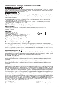
4. Place the flat surface of the tapered end of the receiver directly onto the circuit breaker or fuse as shown. (Figure 3)
If the receiver is held at any other angle, inaccurate readings may occur.
5. Slide the nose of the receiver along the outer edge of each row of breakers using a racetrack pattern as shown
(Figure 4). Note that the receiver will beep frequently as it measures the relative signal strength during the first pass.
6. Repeat step 5. On the second pass, the receiver will beep and the red LED will light, and the receiver will beep only
on the circuit breaker powering the transmitter.
7. Trip the breaker off and check that the LED on the transmitter in the outlet is off to confirm you have found the
correct breaker or fuse.
Locating a Circuit Breaker or Fuse Controlling an Incandescent Light Fixture
1. If the incandescent light fixture is controlled by a wall switch, make sure the wall switch is OFF.
2. Remove light bulb.
3. Install a Screw-in socket adapter (not included).
4. Plug the transmitter into the adapter.
5. Turn on the wall switch and follow the procedure described in Locating a Circuit Breaker or Fuse, steps 3 through 7.
Note: If used on a circuit controlled by a dimmer, turn the dimmer to the highest on position.
61-532
Receiver
for 61-532
12
0V
A
C
Circuit Breaker Finde
r
Transmitter
for 61-532
120V AC Circuit
Breaker Finder
IDEAL INDUSTRIES, INC.
Sycamore, IL 60178 U.S.A.
125VAC Max./0.6W
CIRCUIT
TESTER
810R
WARNING
Arc Flash and Shock Hazard, Proper PPE
Required. Follow all safety procedures, wear
proper PPE in accordance to NFPA 70E.
Read and fully understand the instruction
manual prior to using this product. Failure to
comply can result in serious injury or death.
Figure 3
Figure 4
Receiver
for 61-532
120V AC Circuit Breaker Finde
r
Power Switch
Battery Compartment
LED
LED
WARNING
Rece
iver
for
61-5
32
12
0V A
C Ci
rcuit
Break
er Fi
nder
Main
Breaker
1
2
3
4
5
6
7
8
9
10
11
12
13
14
15
16
17
18
19
20
"Loading the manual" means you need to wait until the file loads and becomes available for online reading. Some manuals are very large, and the time they take to appear depends on your internet speed.
Was this manual helpful?
About this manual
- Brand
- IDEAL
- Model
- 61-532
- Document type
- User Manual
- Category
- Measuring Instrument
- Language(s)
- English, Spanish, French
- Pages
- 6
- File size
- 1.1 MB
- Format
Ask a question
Related manuals
Other IDEAL appliances
 IDEAL 30 Manual
- IDEAL 36 Manual
 IDEAL 61-096 User Manual
 IDEAL 61-310 Manual
 IDEAL 61-327 User Manual
 IDEAL 61-337 User Manual
 IDEAL 61-340 Manual
 IDEAL 61-347 User Manual
 IDEAL 61-357 User Manual
 IDEAL 61-405 User Manual
 IDEAL 61-415 User Manual
 IDEAL 61-557 User Manual
 IDEAL 61-737 User Manual
 IDEAL 61-744 User Manual
 IDEAL 61-747 User Manual
 IDEAL 61-757 User Manual
 IDEAL 61-775 User Manual
 IDEAL 2220 Manual
- IDEAL 2240 Manual
- IDEAL 2260 Manual