Page 2 - Notices
© Copyright 2017, Hewlett Packard Enterprise Development LP Notices The information contained herein is subject to change without notice. The only warranties for Hewlett PackardEnterprise products and services are set forth in the express warranty statements accompanying suchproducts and services. N...
Page 8 - Component identification; Front panel components
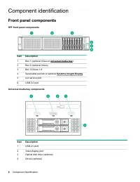
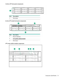
Component identification Front panel components SFF front panel components Item Description 1 Box 1 (optional drives or universal media bay ) 2 Box 2 (optional drives) 3 Box 3 Drives 1-8 4 Serial label pull tab or optional Systems Insight Display 5 iLO service port 6 USB 3.0 port Universal media bay...
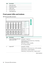
Page 10 - Front panel LEDs and buttons
Item Description 1 Optical disk drive 2 Serial label pull tab 3 USB 3.0 port 4 iLO service port 5 Video display port Front panel LEDs and buttons SFF front panel LEDs and button Item Description Status 1 Power On/Standby button andsystem power LED* Solid green = System on Flashing green (1 Hz/cycle ...
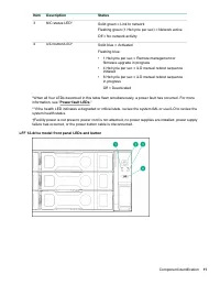
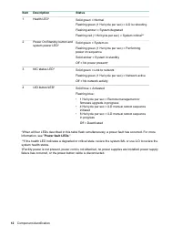
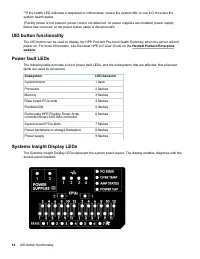
Page 14 - UID button functionality; Power fault LEDs; Systems Insight Display LEDs
**If the health LED indicates a degraded or critical state, review the system IML or use iLO to review thesystem health status. †Facility power is not present, power cord is not attached, no power supplies are installed, power supplyfailure has occurred, or the power button cable is disconnected. UI...
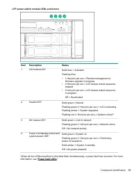
Page 15 - Systems Insight Display combined LED descriptions
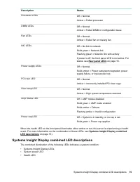
Description Status Processor LEDs Off = Normal Amber = Failed processor DIMM LEDs Off = Normal Amber = Failed DIMM or configuration issue Fan LEDs Off = Normal Amber = Failed fan or missing fan NIC LEDs Off = No link to network Solid green = Network link Flashing green = Network link with activity I...
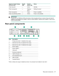
Page 17 - Rear panel components
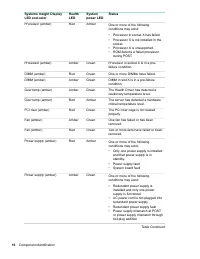
Systems Insight DisplayLED and color HealthLED Systempower LED Status Power cap (off) — Amber Standby Power cap (green) — Flashinggreen Waiting for power Power cap (green) — Green Power is available. Power cap (flashing amber) — Amber Power is not available. IMPORTANT: If more than one DIMM slot LED...
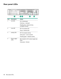
Page 18 - Rear panel LEDs
Rear panel LEDs Item Description Status 1 UID LED Off = Deactivated Solid blue = Activated Flashing blue = System beingmanaged remotely 2 Link LED Off = No network link Green = Network link 3 Activity LED Off = No network activity Solid green = Link to network Flashing green = Network activity 4 Pow...
Page 19 - System board components
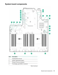
System board components Item Description 1 FlexibleLOM connector 2 System maintenance switch 3 Primary PCIe riser connector 4 Front display port/USB 2.0 connector Table Continued System board components 19
Page 20 - System maintenance switch descriptions
Item Description 5 x4 SATA port 1 6 x4 SATA port 2 7 x2 SATA port 3 8 x1 SATA port 4 9 Optical disk drive/SATA port 5 10 Front power/USB 3.0 connector 11 Drive backplane power connectors 12 Smart Storage Battery connector 13 Chassis intrusion detection connector 14 Drive backplane power connector 15...
Page 21 - Processor, heatsink, and socket components; Drives
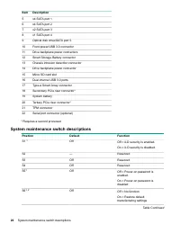
Position Default Function S7 — Reserved S8 — Reserved S9 — Reserved S10 — Reserved S11 — Reserved S12 — Reserved 1 You can access the redundant ROM by setting S1, S5, and S6 to On. 2 When the system maintenance switch position 6 is set to the On position, the system is prepared to restore all config...
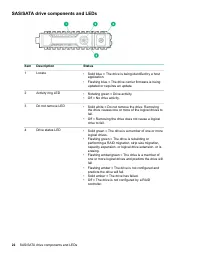
Page 22 - SAS/SATA drive components and LEDs
SAS/SATA drive components and LEDs Item Description Status 1 Locate • Solid blue = The drive is being identified by a host application. • Flashing blue = The drive carrier firmware is being updated or requires an update. 2 Activity ring LED • Rotating green = Drive activity.• Off = No drive activity...
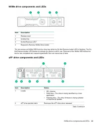
Page 23 - NVMe drive components and LEDs; uFF drive components and LEDs
NVMe drive components and LEDs Item Description 1 Release lever 2 Activity ring 3 Do Not Remove LED 1 4 Request to Remove NVMe Drive button 1 Do not remove an NVMe SSD from the drive bay while the Do Not Remove button LED is flashing. The Do Not Remove button LED flashes to indicate the device is st...
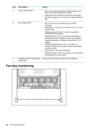
Page 24 - Fan bay numbering
Item Description Status 3 Do not remove LED • Off—OK to remove the drive. Removing the drive does not cause a logical drive to fail. • Solid white—Do not remove the drive. Removing the drive causes one or more of the logical drives tofail. 4 Drive status LED • Off—The drive is not configured by a RA...
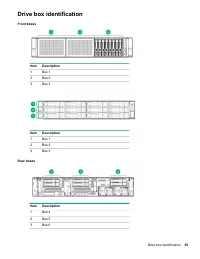
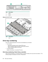
Page 26 - Drive bay numbering: Smart Array controller
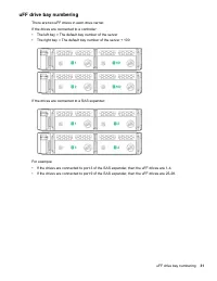
Item Description 1 Box 4 2 Box 6 Midplane box (LFF only) Item Description 1 Box 7 Drive bay numbering Drive bay numbering depends on how the drive backplanes are connected: • To a controller ◦ Embedded controllers use the onboard SATA ports.◦ Type-a controllers install to the type-a smart array conn...
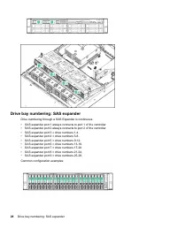
Page 28 - Drive bay numbering: SAS expander
Drive bay numbering: SAS expander Drive numbering through a SAS Expander is continuous. • SAS expander port 1 always connects to port 1 of the controller.• SAS expander port 2 always connects to port 2 of the controller.• SAS expander port 3 = drive numbers 1-4.• SAS expander port 4 = drive numbers ...
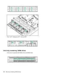
Page 30 - Drive bay numbering: NVMe drives
Front 12LFF + Midplane 4LFF + All rear 2SFF: Drive bay numbering: NVMe drives If the server is populated with NVMe drives and NVMe risers: 30 Drive bay numbering: NVMe drives
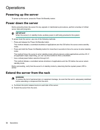
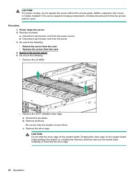
Page 32 - Operations; Powering up the server
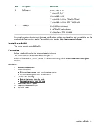
Operations Powering up the server To power up the server, press the Power On/Standby button. Power down the server Before powering down the server for any upgrade or maintenance procedures, perform a backup of criticalserver data and programs. IMPORTANT: When the server is in standby mode, auxiliary...
Page 34 - Removing the server from the rack; Installing the server into the rack
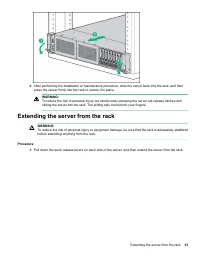
Removing the server from the rack To remove the server from a Hewlett Packard Enterprise, Compaq-branded, Telco, or third-party rack: Procedure 1. Power down the server . 2. Extend the server from the rack . 3. Disconnect the cabling and remove the server from the rack.For more information, see the ...
Page 37 - Removing the air baffle or midplane drive cage
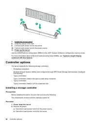
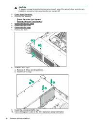
Installing the fan cage CAUTION: Do not operate the server for long periods with the access panel open or removed. Operating the serverin this manner results in improper airflow and improper cooling that can lead to thermal damage. IMPORTANT: For optimum cooling, install fans in all primary fan loca...
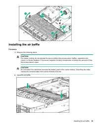
Page 39 - Installing the air baffle
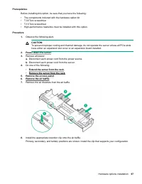
Installing the air baffle Procedure 1. Observe the following alerts. CAUTION: For proper cooling, do not operate the server without the access panel, baffles, expansion slotcovers, or blanks installed. If the server supports hot-plug components, minimize the amount of timethe access panel is open. C...
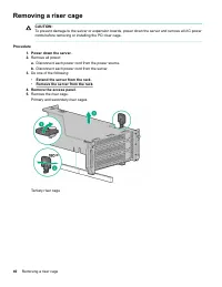
Page 40 - Removing a riser cage
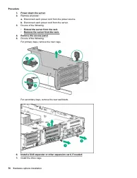
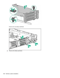
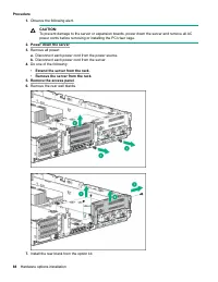
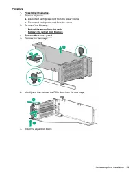
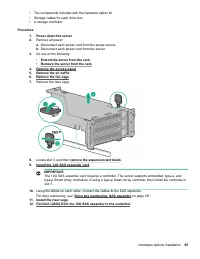
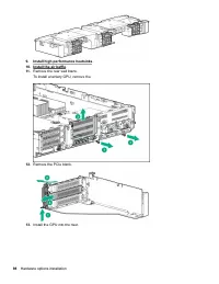
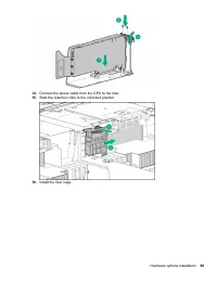
Removing a riser cage CAUTION: To prevent damage to the server or expansion boards, power down the server and remove all AC powercords before removing or installing the PCI riser cage. Procedure 1. Power down the server . 2. Remove all power: a. Disconnect each power cord from the power source. b. D...
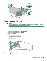
Page 41 - Removing a riser slot blank; Removing the hard drive blank
Removing a riser slot blank CAUTION: To prevent improper cooling and thermal damage, do not operate the server unless all PCI slots haveeither an expansion slot cover or an expansion board installed. Procedure 1. Power down the server . 2. Remove all power: a. Disconnect each power cord from the pow...
Page 44 - Setup; HPE support services; Operational requirements; Space and airflow requirements
Setup HPE support services Delivered by experienced, certified engineers, HPE support services help you keep your servers up andrunning with support packages tailored specifically for HPE ProLiant systems. HPE support services let youintegrate both hardware and software support into a single package...
Page 46 - Power requirements; Server warnings and cautions
CAUTION: To reduce the risk of damage to the equipment when installing third-party options: • Do not permit optional equipment to impede airflow around the server or to increase the internal rack temperature beyond the maximum allowable limits. • Do not exceed the manufacturer’s TMRA. Power requirem...
Page 47 - Rack warnings; Electrostatic discharge
WARNING: To reduce the risk of personal injury from hot surfaces, allow the drives and the internal systemcomponents to cool before touching them. WARNING: To reduce the risk of personal injury, electric shock, or damage to the equipment, remove the powercord to remove power from the server. The fro...
Page 48 - Configuring the server
• Avoid touching pins, leads, or circuitry.• Always be properly grounded when touching a static-sensitive component or assembly. Use one or more of the following methods when handling or installing electrostatic-sensitive parts: ◦ Use a wrist strap connected by a ground cord to a grounded workstatio...
Page 50 - Product QuickSpecs
Hardware options installation Product QuickSpecs For more information about product features, specifications, options, configurations, and compatibility, see theproduct QuickSpecs on the Hewlett Packard Enterprise website ( http://www.hpe.com/info/qs ). Introduction If more than one option is being ...
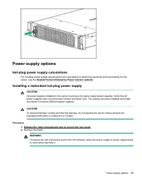
Page 51 - Hot-plug power supply calculations; Installing a redundant hot-plug power supply
Power supply options Hot-plug power supply calculations For hot-plug power supply specifications and calculators to determine electrical and heat loading for theserver, see the Hewlett Packard Enterprise Power Advisor website . Installing a redundant hot-plug power supply CAUTION: All power supplies...
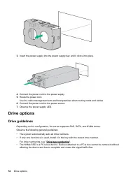
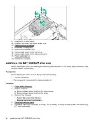
Page 52 - Drive guidelines
3. Insert the power supply into the power supply bay until it clicks into place. 4. Connect the power cord to the power supply. 5. Route the power cord.Use the cable management arm and best practices when routing cords and cables. 6. Connect the power cord to the power source. 7. Observe the power s...
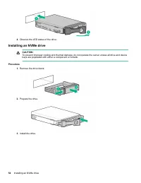
Page 54 - Installing an NVMe drive
4. Observe the LED status of the drive. Installing an NVMe drive CAUTION: To prevent improper cooling and thermal damage, do not operate the server unless all drive and devicebays are populated with either a component or a blank. Procedure 1. Remove the drive blank. 2. Prepare the drive. 3. Install ...
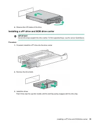
Page 55 - Installing a uFF drive and SCM drive carrier
4. Observe the LED status of the drive. Installing a uFF drive and SCM drive carrier IMPORTANT: Not all drive bays support the drive carrier. To find supported bays, see the server QuickSpecs. Procedure 1. If needed, install the uFF drive into the drive carrier. 2. Remove the drive blank. 3. Install...
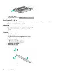
Page 56 - Installing an M.2 drive
4. Power on the server.To configure the drive, use HPE Smart Storage Administrator . Installing an M.2 drive This procedure is for replacing M.2 drives located on an expansion card, riser, or the system board only. Donot use this procedure to replace uFF drives. Prerequisites Before installing this ...
Page 57 - Fan options
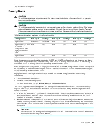
The installation is complete. Fan options CAUTION: To avoid damage to server components, fan blanks must be installed in fan bays 1 and 2 in a single-processor configuration. CAUTION: To avoid damage to the equipment, do not operate the server for extended periods of time if the serverdoes not have ...
Page 58 - Installing high-performance fans
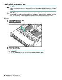
Installing high-performance fans CAUTION: Caution: To prevent damage server, ensure that all DIMM latches are closed and locked before installingthe fans. CAUTION: Do not operate the server for long periods with the access panel open or removed. Operating the serverin this manner results in improper...
Page 59 - DIMM population information
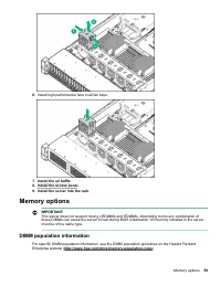
6. Install high-performance fans in all fan bays. 7. Install the air baffle . 8. Install the access panel . 9. Install the server into the rack . Memory options IMPORTANT: This server does not support mixing LRDIMMs and RDIMMs. Attempting to mix any combination ofthese DIMMs can cause the server to ...
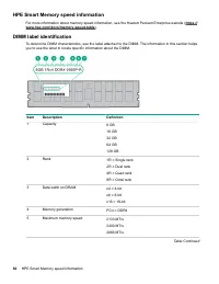
Page 61 - Installing a DIMM
Item Description Definition 6 CAS latency P = CAS 15-15-15 T = CAS 17-17-17 U = CAS 20-18-18 V = CAS 19-19-19 (for RDIMM, LRDIMM) V = CAS 22-19-19 (for 3DS TSVLRDIMM) 7 DIMM type R = RDIMM (registered) L = LRDIMM (load reduced) E = Unbuffered ECC (UDIMM) For more information about product features, ...
Page 62 - Controller options; Installing a storage controller
7. Install the access panel . 8. Install the server in the rack. 9. Connect each power cord to the server. 10. Connect each power cord to the power source. 11. Power up the server . Use the BIOS/Platform Configuration (RBSU) in the UEFI System Utilities to configure the memory mode. For more informa...
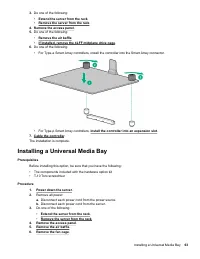
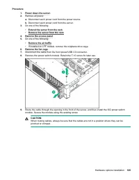
Page 63 - Installing a Universal Media Bay
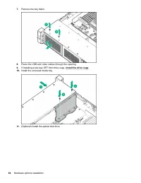
3. Do one of the following: • Extend the server from the rack . • Remove the server from the rack . 4. Remove the access panel . 5. Do one of the following: • Remove the air baffle . • If installed, remove the 4LFF midplane drive cage . 6. Do one of the following: • For Type-a Smart Array controller...
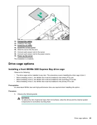
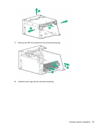
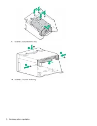
Page 65 - Drive cage options; Installing a front 8NVMe SSD Express Bay drive cage
12. Connect the cables . 13. Install the fan cage. 14. Install the air baffle . 15. Install the access panel . 16. Slide the server into the rack. 17. Connect each power cord to the server. 18. Connect each power cord to the power source. 19. Power up the server . The installation is complete. Drive...
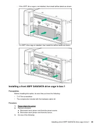
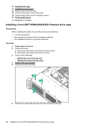
Page 67 - Installing a front 6SFF SAS/SATA + 2NVMe Premium drive cage
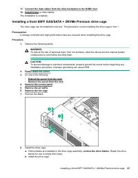
11. Connect the data cables from the drive backplane to the NVMe riser . 12. Install drives or drive blanks. The installation is complete. Installing a front 6SFF SAS/SATA + 2NVMe Premium drive cage The drive cage can be installed in any box. This procedure covers installing the drive cage in box 1....
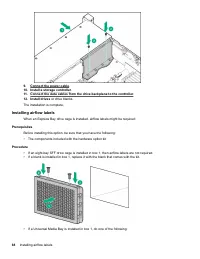
Page 69 - Installing a front 8SFF SAS/SATA drive cage in box 1
◦ If the 2SFF drive cage is not installed, then install airflow labels as shown. ◦ If a 2SFF drive cage is installed, then install the airflow labels as shown. Installing a front 8SFF SAS/SATA drive cage in box 1 Prerequisites Before installing this option, be sure that you have the following: • T-1...
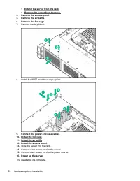
Page 71 - Installing a front 8SFF SAS/SATA drive cage in box 2
Installing a front 8SFF SAS/SATA drive cage in box 2 Procedure 1. Power down the server . 2. Remove all power: a. Disconnect each power cord from the power source. b. Disconnect each power cord from the server. 3. Do one of the following: • Extend the server from the rack . • Remove the server from ...
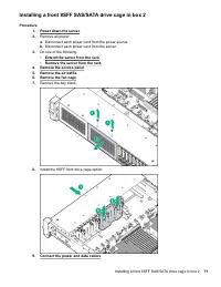
Page 72 - Installing a front 2SFF NVMe/SAS/SATA Premium drive cage
10. Install the fan cage . 11. Install the access panel . 12. Slide the server into the rack. 13. Connect each power cord to the server. 14. Connect each power cord to the power source. 15. Power up the server . The installation is complete. Installing a front 2SFF NVMe/SAS/SATA Premium drive cage P...
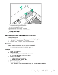
Page 75 - Installing a midplane 4LFF SAS/SATA drive cage
11. Connect the power and data cables . 12. Install the access panel . 13. Slide the server into the rack. 14. Connect each power cord to the server. 15. Connect each power cord to the power source. 16. Power up the server . The installation is complete. Installing a midplane 4LFF SAS/SATA drive cag...
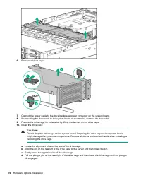
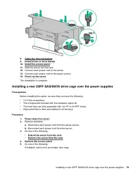
Page 79 - Installing a rear 2SFF SAS/SATA drive cage over the power supplies
8. Cable the drive backplane . 9. Install drives or drive blanks . 10. Install the access panel . 11. Slide the server into the rack. 12. Connect each power cord to the server. 13. Connect each power cord to the power source. 14. Power up the server . The installation is complete. Installing a rear ...
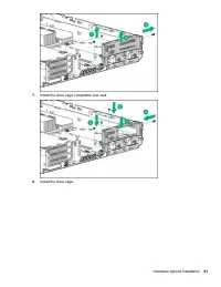
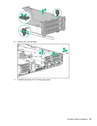
Page 82 - Installing a rear 3LFF SAS/SATA drive cage
9. Install drives or drive blanks. 10. Install the secondary rear wall or a riser cage. 11. Cable the drive backplane . 12. Install the access panel . 13. Slide the server into the rack. 14. Connect each power cord to the server. 15. Connect each power cord to the power source. 16. Power up the serv...
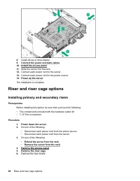
Page 84 - Riser and riser cage options; Installing primary and secondary risers
8. Install drives or drive blanks. 9. Connect the power and data cables . 10. Install the access panel . 11. Slide the server into the rack. 12. Connect each power cord to the server. 13. Connect each power cord to the power source. 14. Power up the server . The installation is complete. Riser and r...
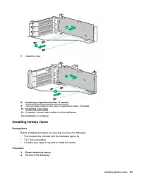
Page 85 - Installing tertiary risers
7. Install the riser. 8. Install any expansion boards, if needed 9. Connect data cables to the riser or expansion board, if needed. 10. Install the riser cage . 11. If needed, connect data cables to drive backlanes. The installation is complete. Installing tertiary risers Prerequisites Before instal...
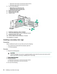
Page 86 - Installing a secondary riser cage
• Disconnect each power cord from the power source.• Disconnect each power cord from the server. 3. Do one of the following: • Extend the server from the rack . • Remove the server from the rack . 4. Remove the access panel . 5. Remove the riser cage . 6. Install the riser. 7. Install any expansion ...
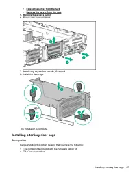
Page 87 - Installing a tertiary riser cage
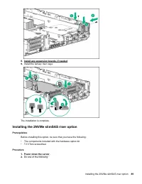
• Extend the server from the rack . • Remove the server from the rack . 5. Remove the access panel . 6. Remove the rear wall blank. 7. Install any expansion boards, if needed . 8. Install the riser cage: The installation is complete. Installing a tertiary riser cage Prerequisites Before installing t...
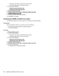
Page 89 - Installing the 2NVMe slimSAS riser option
8. Install any expansion boards, if needed9. Install the tertiary riser cage: The installation is complete. Installing the 2NVMe slimSAS riser option Prerequisites Before installing this option, be sure that you have the following: • The components included with the hardware option kit• T-10 Torx sc...
Page 90 - Installing the 8NVMe slimSAS riser option
• Disconnect each power cord from the power source.• Disconnect each power cord from the server. 3. Do one of the following: • Extend the server from the rack . • Remove the server from the rack . 4. Remove the access panel . 5. Using the labels on the cable, connect the cables to the riser . 6. Ins...
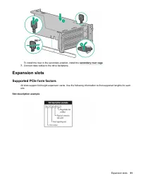
Page 91 - Supported PCIe form factors
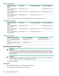
To install the riser in the secondary position, install the secondary riser cage . 7. Connect data cables to the drive backplane. Expansion slots Supported PCIe form factors All slots support full-height expansion cards. Use the following information to find supported lengths for eachslot. Slot desc...
Page 92 - Installing expansion boards
Primary riser connector PCIe slot and cardlength 3-slot riser* 2-slot riser (Optional) 2-slot riser (Optional) Slot 1 - Full-length/Full-height (FL/FH) PCIe3 x8 (8, 4, 2, 1) — PCIe3 x16 (16, 8, 4, 2, 1) Slot 2 - Half-length/Full-height (HL/FH) PCIe3 x16 (16, 8, 4, 2, 1) PCIe3 x16 (16, 8, 4, 2, 1) PC...
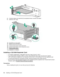
Page 94 - Installing a 12G SAS Expander Card
8. If internal cables are required for the expansion board, connect the cables. 9. Install the riser cage. 10. Install the access panel . 11. Slide the server into the rack. 12. Connect each power cord to the server. 13. Connect each power cord to the power source. 14. Power up the server . The inst...
Page 100 - Installing an intrusion detection switch
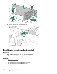
17. Slide the retention clips to the locked position. The installation is complete. Installing an intrusion detection switch Prerequisites Before installing this option, be sure that you have the following: • The components included with the hardware option kit Procedure 1. Power down the server . 2...
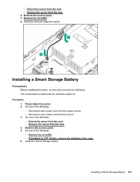
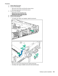
Page 101 - Installing a Smart Storage Battery
• Extend the server from the rack . • Remove the server from the rack . 4. Remove the access panel . 5. Remove the air baffle . 6. Install the intrusion detection switch. Installing a Smart Storage Battery Prerequisites Before installing this option, be sure that you have the following: The componen...
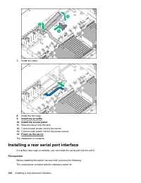
Page 102 - Installing a rear serial port interface
7. Install the cable. 8. Install the fan cage. 9. Install the air baffle . 10. Install the access panel . 11. Slide the server into the rack. 12. Connect each power cord to the server. 13. Connect each power cord to the power source. 14. Power up the server . The installation is complete. Installing...
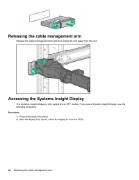
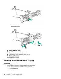
Page 104 - Installing a Systems Insight Display
Install the serial port. 6. Install the access panel . 7. Install the server in the rack. 8. Connect each power cord to the server. 9. Connect each power cord to the power source. 10. Power up the server . The installation is complete. Installing a Systems Insight Display Prerequisites Before instal...
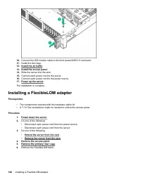
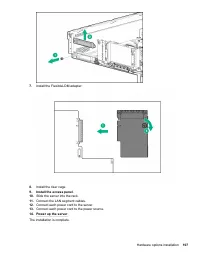
Page 106 - Installing a FlexibleLOM adapter
10. Connect the SID module cable to the front power/USB 3.0 connector. 11. Install the fan cage. 12. Install the air baffle . 13. Install the access panel . 14. Slide the server into the rack. 15. Connect each power cord to the server. 16. Connect each power cord to the power source. 17. Power up th...
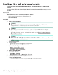
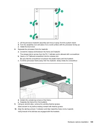
Page 108 - Installing a 1U or high-performance heatsink
Installing a 1U or high-performance heatsink This procedure shows a standard heatsink as an example. The installation process is the same for allheatsinks. HPE recommends identifying the processor, heatsink, and socket components before performing this procedure. Prerequisites Before installing this...
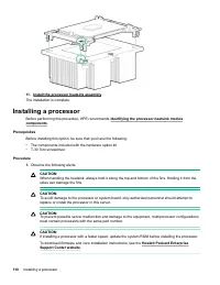
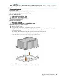
Page 110 - Installing a processor
11. Install the processor heatsink assembly . The installation is complete. Installing a processor Before performing this procedure, HPE recommends identifying the processor-heatsink module components . Prerequisites Before installing this option, be sure that you have the following: • The component...
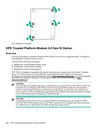
Page 112 - HPE Trusted Platform Module 2.0 Gen10 Option; Overview
The installation is complete. HPE Trusted Platform Module 2.0 Gen10 Option Overview Use these instructions to install and enable an HPE TPM 2.0 Gen10 Kit in a supported server. This option isnot supported on Gen9 and earlier servers. This procedure includes three sections: 1. Installing the Trusted ...
Page 113 - HPE Trusted Platform Module 2.0 Guidelines; Disabling Chipset-TPM; Installing and enabling the HPE TPM 2.0 Gen10 Kit; Installing the Trusted Platform Module board
IMPORTANT: In UEFI Boot Mode, the HPE TPM 2.0 Gen10 Kit can be configured to operate as TPM 2.0 (default) orTPM 1.2 on a supported server. In Legacy Boot Mode, the configuration can be changed between TPM1.2 and TPM 2.0, but only TPM 1.2 operation is supported. HPE Trusted Platform Module 2.0 Guidel...
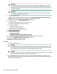
Page 114 - Installing the TPM board and cover
WARNING: To reduce the risk of personal injury, electric shock, or damage to the equipment, remove powerfrom the server by removing the power cord. The front panel Power On/Standby button does notshut off system power. Portions of the power supply and some internal circuitry remain active untilAC po...
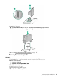
Page 115 - Preparing the server for operation
3. Install the TPM cover: a. Line up the tabs on the cover with the openings on either side of the TPM connector. b. To snap the cover into place, firmly press straight down on the middle of the cover. 4. Proceed to Preparing the server for operation on page 115. Preparing the server for operation P...
Page 118 - Cabling; HPE ProLiant Gen10 DL Servers Storage Cabling Guidelines
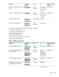
Cabling HPE ProLiant Gen10 DL Servers Storage Cabling Guidelines When installing cables, observe the following: • All ports are labeled: ◦ System board ports◦ Controller ports◦ 12G SAS Expander ports • Most data cables have labels near each connector with destination port information.• Some data cab...
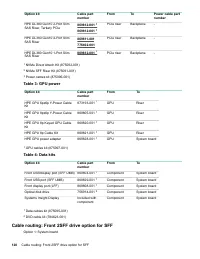
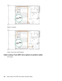
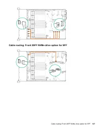
Page 120 - Cable routing: Front 2SFF drive option for SFF
Option kit Cable partnumber From To Power cable partnumber HPE DL380 Gen10 2-Port SlimSAS Riser, Tertiary PCIe 869812-001 1 869812-001 1 PCIe riser Backplane - HPE DL380 Gen10 4-Port SlimSAS Riser 869811-001 776402-001 PCIe riser Backplane - HPE DL380 Gen10 1-Port SlimSAS Riser 869812-001 1 PCIe ris...
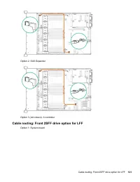
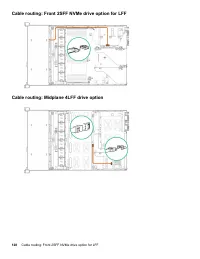
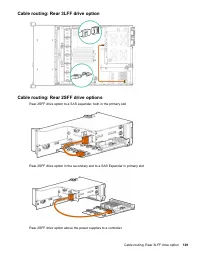
Page 121 - Cable routing: Front 2SFF drive option for LFF
Option 2: SAS Expander Option 3 (not shown): A controller Cable routing: Front 2SFF drive option for LFF Option 1: System board Cable routing: Front 2SFF drive option for LFF 121
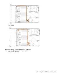
Page 123 - Cable routing: Front 8SFF drive options
LFF models Cable routing: Front 8SFF drive options Box 1 to SAS Expander Cable routing: Front 8SFF drive options 123
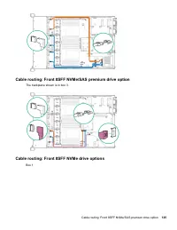
Page 125 - Cable routing: Front 8SFF NVMe drive options
Cable routing: Front 8SFF NVMe/SAS premium drive option The backplane shown is in box 3. Cable routing: Front 8SFF NVMe drive options Box 1 Cable routing: Front 8SFF NVMe/SAS premium drive option 125
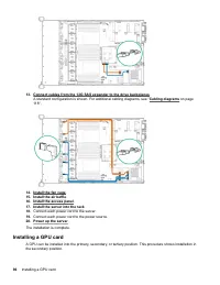
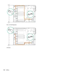
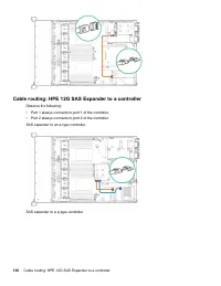
Page 130 - Cable routing: HPE 12G SAS Expander to a controller
Cable routing: HPE 12G SAS Expander to a controller Observe the following: • Port 1 always connects to port 1 of the controller.• Port 2 always connects to port 2 of the controller. SAS expander to an a-type controller SAS expander to a p-type controller 130 Cable routing: HPE 12G SAS Expander to a ...
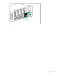
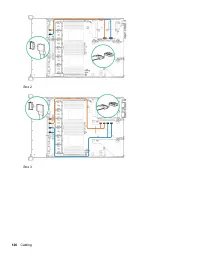
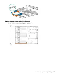
Page 131 - Cable routing: Systems Insight Display
Cable routing: Systems Insight Display An SFF model is shown. The routing is the same for LFF. Cable routing: Systems Insight Display 131
Page 132 - Software and configuration utilities; Server mode; Active Health System
Software and configuration utilities Server mode The software and configuration utilities presented in this section operate in online mode, offline mode, or inboth modes. Software or configuration utility Server mode Active Health System on page 132 Online and Offline HPE iLO 5 on page 133 Online an...
Page 133 - Active Health System Log; HPE iLO 5; iLO Federation
• Consolidated health and service alerts with precise time stamps• Agentless monitoring that does not affect application performance For more information about the Active Health System, see the iLO user guide on the Hewlett PackardEnterprise website. Active Health System data collection The Active H...
Page 134 - iLO RESTful API
iLO 5 supports the following features: • Group health status—View server health and model information.• Group Virtual Media—Connect scripted media for access by the servers in an iLO Federation group.• Group power control—Manage the power status of the servers in an iLO Federation group.• Group powe...
Page 135 - iLO Amplifier Pack; Intelligent Provisioning; Intelligent Provisioning operation
For more information, see the following website: http://www.hpe.com/info/resttool . iLO Amplifier Pack The iLO Amplifier Pack is an advanced server inventory and firmware and driver update solution that enablesrapid discovery, detailed inventory reporting, and firmware and driver updates by leveragi...
Page 136 - Management Security; Scripting Toolkit for Windows and Linux; UEFI System Utilities
• SUSE Linux Enterprise Server• VMware ESXi/vSphere Custom Image Not all versions of an OS are supported. For information about specific versions of a supported operatingsystem, see the OS Support Matrix on the Hewlett Packard Enterprise website ( http://www.hpe.com/info/ ossupport ). Management Sec...
Page 138 - Launching the Embedded UEFI Shell; HPE Smart Storage Administrator
• Using the System Utilities options described in the following sections. • Using the RESTful API to clear and restore certificates. For more information, see the Hewlett Packard Enterprise website ( www.hpe.com/support/restfulinterface/docs ). • Using the secboot command in the Embedded UEFI Shell ...
Page 139 - USB support; External USB functionality; Redundant ROM support; Safety and security benefits; Keeping the system current; Updating firmware or system ROM; Service Pack for ProLiant
For more information, see HPE Smart Array SR Gen10 Configuration Guide at the Hewlett Packard Enterprise website . USB support Hewlett Packard Enterprise Gen10 servers support all USB operating speeds depending on the device that isconnected to the server. External USB functionality Hewlett Packard ...
Page 141 - Online Flash components
NOTE: Do not manage one node with iLO Amplifier Pack and HPE OneView. Updating firmware from the System Utilities Use the Firmware Updates option to update firmware components in the system, including the system BIOS, NICs, and storage cards. Procedure 1. Access the System ROM Flash Binary component...
Page 144 - Troubleshooting; NMI functionality; Troubleshooting resources
Troubleshooting NMI functionality An NMI crash dump enables administrators to create crash dump files when a system is hung and notresponding to traditional debugging methods. An analysis of the crash dump log is an essential part of diagnosing reliability problems, such as hangingoperating systems,...
Page 145 - Safety, warranty, and regulatory information; Safety and regulatory compliance; Warranty information; Belarus Kazakhstan Russia marking
Safety, warranty, and regulatory information Safety and regulatory compliance For important safety, environmental, and regulatory information, see Safety and Compliance Information for Server, Storage, Power, Networking, and Rack Products , available at the Hewlett Packard Enterprise website . Warra...
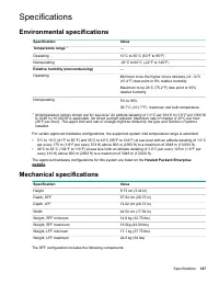
Page 147 - Specifications; Environmental specifications
Specifications Environmental specifications Specification Value Temperature range 1 — Operating 10°C to 35°C (50°F to 95°F) Nonoperating -30°C to 60°C (-22°F to 140°F) Relative humidity (noncondensing) — Operating Minimum to be the higher (more moisture) of -12°C(10.4°F) dew point or 8% relative hum...
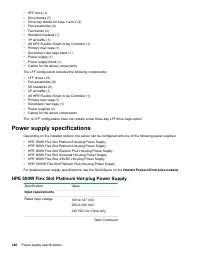
Page 148 - Power supply specifications; HPE 500W Flex Slot Platinum Hot-plug Power Supply
• SFF drive (1)• Drive blanks (7)• Drive bay blanks for bays 1 and 2 (2)• Fan assemblies (4)• Fan blanks (2)• Standard heatsink (1)• 1P air baffle (1)• X8 HPE Flexible Smart Array Controller (1)• Primary riser cage (1)• Secondary riser cage blank (1)• Power supply (1)• Power supply blank (1)• Cables...
Page 149 - HPE 800W Flex Slot Platinum Hot-plug Power Supply
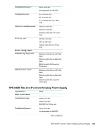
Rated input frequency 50 Hz to 60 Hz Not applicable to 240 VDC Rated input current 5.8 A at 100 VAC 2.8 A at 200 VAC 2.4 A at 240 VDC for Chinaonly Maximum rated input power 580 W at 100 VAC 560 W at 200 VAC 576 W at 240 VDC for Chinaonly BTUs per hour 1979 at 100 VAC 1911 at 200 VAC 1965 at 240 VDC...
Page 150 - HPE 800W Flex Slot Titanium Plus Hot-plug Power Supply
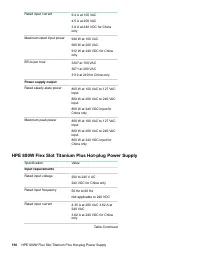
Rated input current 9.4 A at 100 VAC 4.5 A at 200 VAC 3.8 A at 240 VDC for Chinaonly Maximum rated input power 940 W at 100 VAC 900 W at 200 VAC 912 W at 240 VDC for Chinaonly BTUs per hour 3207 at 100 VAC 3071 at 200 VAC 3112 at 240 for China only Power supply output Rated steady-state power 800 W ...
Page 151 - HPE 800W Flex Slot Universal Hot-plug Power Supply
Maximum rated input power 870 W at 200 VAC 870 W at 240 VAC 870 W at 240 VDC for Chinaonly BTUs per hour 2969 at 200 VAC 2969 at 240 VAC 2969 at 240 VDC for Chinaonly Power supply output Rated steady-state power 800 W at 200 VAC to 240 VACinput 800 W at 240 VDC input forChina only Maximum peak power...
Page 152 - HPE 800W Flex Slot -48VDC Hot-plug Power Supply
Rated steady-state power 800 W at 200 VAC to 277 VACinput 800 W at 380 VDC input Maximum peak power 800 W at 200 VAC to 277 VACinput 800 W at 380 VDC input HPE 800W Flex Slot -48VDC Hot-plug Power Supply Specification Value Input requirements Rated input voltage -40 VDC to -72 VDC -48 VDC nominal in...
Page 153 - HPE 1600W Flex Slot Platinum Hot Plug Power Supply
CAUTION: This equipment is designed to permit the connection of the earthed conductor of the DC supply circuit tothe earthing conductor at the equipment. If this connection is made, all of the following must be met: • This equipment must be connected directly to the DC supply system earthing electro...
Page 154 - Accessing Hewlett Packard Enterprise Support; Accessing updates; Customer self repair
Support and other resources Accessing Hewlett Packard Enterprise Support • For live assistance, go to the Contact Hewlett Packard Enterprise Worldwide website: http://www.hpe.com/assistance • To access documentation and support services, go to the Hewlett Packard Enterprise Support Center website: h...
Page 156 - Documentation feedback
Regulatory information To view the regulatory information for your product, view the Safety and Compliance Information for Server, Storage, Power, Networking, and Rack Products , available at the Hewlett Packard Enterprise Support Center: www.hpe.com/support/Safety-Compliance-EnterpriseProducts Addi...