Haier HSU24VHJDBG - Installation Manual
Haier HSU24VHJDBG – Installation Manual, read for free online in PDF format. We hope this helps you resolve any issues you may have. If you have further questions, please contact us through the contact form.


Table of Contents:
- Page 2 – Indoor unit; Note; Accessory parts
- Page 3 – CAUTION; Outdoor unit A
- Page 5 – Manual de instalación de aparato de aire acondicionado; Preparación; Unidad interior – Elija una ubicación que sea
- Page 6 – Unidad interior; Entubación trasera izquierda]; Nota
- Page 7 – Unidad exterior
- Page 9 – Manuel d'installation d'un climatiseur de pièce; Préparation; Unité intérieure – Sélectionnez un emplacement qui soit; Schéma de l'installation des unités intérieures et extérieures; Fixation de l'unité extérieure
- Page 12 – AVERTISSEMENT
- Page 13 – Drawing for the installation of indoor and outdoor units; Necessary Tools for Installation; Preparation; Installation Manual of Room Air Conditioner
- Page 15 – Installation of Outdoor Unit; Connection
- Page 17 – Herramientas necesarias para realizar la instalación; diagrama de instalación de unidades interiores y exteriores.; Fijación de la unidad exterior
- Page 18 – Instalar la placa de montaje y ubicar el orificio en la pared; [Izquierda • Entubación trasera izquierda]; Conexión de los cables eléctricos de interior/exterior; Accesorios; Al fijar por primera vez la placa de montaje; Al conectar el cable después de instalar la unidad de interior; Extracción de los tubos; Al conectar el cable antes de instalar la unidad de interior
- Page 19 – PRECAUCIÓN
- Page 20 – Etiqueta de carga de refrigerante; Escriba una marca; Compruebe los siguientes
- Page 21 – Outillage requis pour l'installation; schéma d'installation des unités intérieures et extérieures
- Page 22 – Unité intérieure; Faire un trou dans le mur et installer le cache-trou de tuyauterie; Accessoires; Lorsque la plaque de fixation est installée pour la 1e fois; Connexion du câble après l'installation de l'unité intérieure; Schéma de la tuyauterie; Connexion du câble avant l'installation de l'unité intérieure
- Page 23 – fils avec terre, 16 AW G; Tous les modèles
- Page 24 – Etiquette de charge de réfrigérant; Cochez les cases; Vérification des composants pour
- Page 27 – Connecting the pipe of gas side; please attach it as; Attaching Drain-Elbow; To bend a pipe, be careful not to crush the pipe,
- Page 31 – Todos los modelo s: Control de dos hilos : 4 hilos , 18AWG; hilos con toma de tierra 12 AWG; Cableado de
- Page 35 – Câble d’alimentation
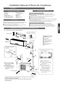
Drawing for the installation of indoor and outdoor units
Necessary Tools for Installation
Hammer
ƽ
Torque wrench
ƽ
(17mm,22mm,26mm)
Nipper
ƽ
Reamer
ƽ
Hacksaw
ƽ
Pipe cutter
ƽ
Gas leakage detector or
ƽ
soap-and-water solution
Hole core drill
ƽ
Flaring tool
ƽ
Spanner(17,19 and 26mm)
ƽ
Knife
ƽ
Measuring tape
ƽ
ƽ
ƽ
ƽ
ƽ
ƽ
Place where the distance of more than lm from televisions, radios, wireless apparatuses
and fluorescent lamps can be left.
ƽ
In the case of fixing the remote controller on a wall, place where the indoor unit can
receive signals when the fluorescent
ƽ
lamps in the room are lightened.
ƽ
ƽ
Place, where discharged wind and noise do not cause a nuisance to the neighbors.
ƽ
Place, where a distance marked
ƽ
is available as illustrated in the above figure.
Before inserting power plug into receptacle, check the voltage without fail.
The power source is the same as the
ƽ
corresponding name plate.
Install an exclusive branch circuit of the power.
ƽ
A receptacle shall be set up in a distance where the power cable can be
reached. Do not extend the cable by cutting it.
ƽ
Selection of Installation Place
Power Source
Preparation
NO.0010526879
Installation Manual of Room Air Conditioner
F
A
C
E
D
Optional parts for piping
Non-adhesive tape
Adhesive tape
Saddle (L.S) with screws
Connecting electric cable
for indoor and outdoor
Drain hose
Heating insulating material
Piping hole cover
Floor fixing dimensions of the
outdoor unit (Unit:mm)
Fixing of outdoor unit
Fix the unit to concrete or block
ƽ
with bolts (10mm) and nuts firmly
and horizontally.
When fitting the unit to wall
ƽ
surface, roof or rooftop, fix
a supporter securely with nails
or wires in consideration of
earthquake and strong wind.
If vibration may affect the
ƽ
house, fix the unit by attaching a
vibration-proof mat.
The marks from
to
in the figure are the
parts numbers.
The distance between
the indoor unit and the
floor should be more
than 2m.
The models adopt HC FC free refrigerant R410A
more than
10cm
more than 5cm
more than 10cm
more than 10cm
more than
10cm
more than 15cm
more than 60cm
A
G
ƽ
ƽ
A
F
C
E
D
G
B
Arrangement of piping
directions
Rear left
Left
Rear
right
Right
Below
G
Attention must be paid to
the rising up of drain hose
The above picture is for your reference only. Your product may look different.
Read this manual before installation.
Explain the operation or the unit to the user according to this manual.
Indoor Unit - Select a plocation that is
Outdoor Unit - Select a plocation that is
Robust not causing vibration, where the body can be supported sufficiently.
Not affected by heat or steam generated in the vicinity, where inlet and outlet of the
unit are not disturbed.
Possible to drain easily, where piping can be connected with the outdoor unit.
Where cold air can be spread in a room evenly.
Nearby a power receptacle. (Refer to drawings).
Not less affected by rain or direct sunlight and is sufficiently ventilated.
Strong enough to bear the unit, where vibration and noise are not increased.
"Loading the manual" means you need to wait until the file loads and becomes available for online reading. Some manuals are very large, and the time they take to appear depends on your internet speed.
Summary
Indoor unit Fix to side bar and lintel a mounting bar, Which is separately sold, and then ƽ fasten the plate to the fixed mounting bar. Refer to the previous article, “ When the mounting plate is ƽ position of wall hole. Make a hole of 60 mm in diameter, slightly descending to outside the wall. ƽ Ins...
1. If the supply cord is damaged, it must be replaced by the manufacturer or its service agent or a similar qualified person. The type of connecting wire is H05RN-F or H07RN-F. 2. If the fuse on PC board is broken please change it with the type of T. 3.15A /250V. 3. The wiring method should be in lin...
Manual de instalación de aparato de aire acondicionado Preparación Herramientas necesarias para realizar la instalación Martillo Llave dinamométrica (17mm, 22mm,26mm) Alicate Sierra de tubos Sierra para metales Herramienta de conicidad Broca de tubo Cuchilla Llave (17, 19 y 26 mm) Metro Detector de ...