GE THQL1115AFP2 - User Manual
GE THQL1115AFP2 Circuit Breaker – User Manual, read for free online in PDF format. We hope this helps you resolve any issues you may have. If you have further questions, please contact us through the contact form.


Branch
Circuit #1
(A-phase)
Branch
Circuit #2
(B-phase)
Panel
AFCI pigtails
Tie handle bars together
with THT104
Neutral lug of second
AFCI can be left open
12/14-2 NM-B
12/14-3 NM-B
12/14-2 NH-B
Junction box
Neutral bar
Red conductor
White conductor
Black conductor
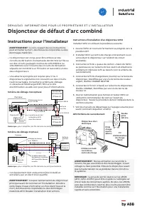
Installer Instructions
WARNING: Failure to follow these instructions could
result in death, personal injury, or property damage.
• This circuit breaker is intended for use on either
single-phase grounded 120Vac 2-wire branch circuits
or on 120/240Vac or 120/208Vac shared neutral
circuits where the neutral from separate branch
circuits is combined to one neutral wire and returned
to either breaker.
• A handle tie is required for 2 or 3 single pole non
common trip breakers on shared neutral circuits. See
wiring diagram below and download DET-719 from
electrification.us.abb.com for additional information.
Single Phase Wiring Diagram
Note: for simplicity the ground wires are not shown
3-Phase Wiring Diagram
Note: for simplicity the ground wires are not shown
• This equipment must be installed and serviced only
by a qualified electrician.
WARNING: Turn off power to main breaker before
beginning installation. Failure to do so will risk
electrical shock and possible death, personal injury,
or property damage.
D E H 4 1 5 4 3 H O M E O W N E R & I N S TA L L E R I N F O R M AT I O N
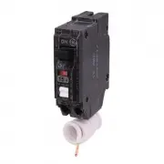
Combination Arc-Fault Circuit Interrupter (AFCI)
Arc-Fault Circuit Interrupter (AFCI)
Installation Instructions
Install the AFCI using the following procedure:
1. Open the AFCI by moving its handle firmly to the
OFF position.
2. Install the AFCI into the load center by plugging
or bolting the circuit breaker into the desired
circuit position.
3. Connect the coiled white “pigtail” wire from the AFCI
to the panel or enclosure neutral bus terminal and
secure it tightly. Uncoil pigtail as necessary (see
connection diagram)
4. Connect the white (neutral) load wire to the terminal
side of the circuit breaker, identified by a silver-
colored terminal screw, labeled LOAD NEUTRAL
5. Connect black (hot) wire to circuit breaker terminals
labeled LOAD, identified by a gold-colored terminal
screw.
6. Turn on power, then close and test the AFCI using the
test rocker switch on the front of the breaker. Follow
the Test Procedure indicated in the next section.
7. See Troubleshooting Guides on the next page on how
to troubleshoot an AFCI.
Arc-Fault Circuit Interrupter
WARNING: Do not reverse-feed or back-wire. Do not
subject to megger, high-voltage, or high-pot tests.
Remove the circuit breaker before high-potting occurs
on the circuit or the system.
NOTE: The neutral pigtail on eMCB’s (AFCI, GFCI and
DFCI) can be cut to length in the field or extended
using approved connectors. Additionally, eMCB’s with
shortened neutrals can be installed as shown
providing a fast and clean installation.
Arc Fault
Circuit
Breaker
120Vac
Duplex
Receptacle
Load
Power
Wire
(Black)
Load
Neutral
Wire
(White)
Short White Wire
Connects to Load
Center Neutral
Black conductor
White conductor
Red conductor
Blue conductor
Neutral Bar
Panel
12/14-2 NM-B
12/14-2 NM-B
12/14-2 NM-B
12/14-2 NM-B
Branch
Circuit #1
(A-Phase)
Branch
Circuit #2
(B-Phase)
Branch
Circuit #3
(C-Phase)
Tie handle bars together
with TQ3HTK
Neutral lug of second
and third AFCI can be
left open
Junction
Box
"Loading the manual" means you need to wait until the file loads and becomes available for online reading. Some manuals are very large, and the time they take to appear depends on your internet speed.