Frigidaire GCWM2767AF - Installation Manual

Frigidaire GCWM2767AF Oven – Installation Manual, read for free online in PDF format. We hope this helps you resolve any issues you may have. If you have further questions, please contact us through the contact form.


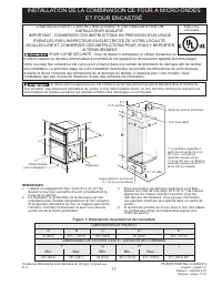
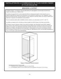
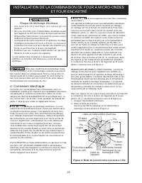
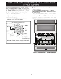
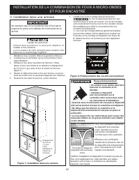
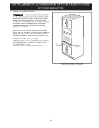
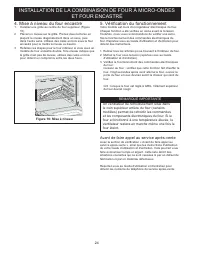
Table of Contents:
- Page 2 – MICROWAVE/WALL OVEN COMBINATION INSTALLATION; Microwave Combination; CARPENTRY and SUPPORT; Figure 2: Wall Oven Braces
- Page 3 – Important Notes to the Installer; IMPORTANT SAFETY; Electrical Requirements
- Page 4 – Electrical connection; Electrical Shock Hazard
- Page 5 – Model and Serial Number Location; Figure 6: Serial Plate Location
- Page 6 – Figure 7: Cabinet Installation; Cabinet Installation; Tip Over Hazard
- Page 7 – Install the Bottom Trims; Figure 9: Bottom Trim
- Page 8 – Checking Operation; Before You Call for Service; Leveling the Wall Oven; the other. Use wood shims under the wall oven to; IMPORTANT NOTE
- Page 9 – INSTALACIÓN DE LA COMBINACIÓN DE HORNO/MICROONDAS; PARA SU SEGURIDAD: No almacene ni use gasolina u otros; Figure 1: Dimensiones del producto y del corte; DIMENSIONES DEL PRODUCTO
- Page 10 – ACOPLAMIENTO EN MUEBLE/ESPACIO y ESTRUCTURAS DE APOYO; espacio necesario para colocar el horno.; Figure 2: Soportes de la pared del horno
- Page 11 – Notas importantes para el instalador; INSTRUCCIONES; Requisitos eléctricos
- Page 12 – Conexión eléctrica; Riesgo de choque eléctrico; Figure 4: Caja de empalme de conexión a tierra de; negros
- Page 13 – Ubicación de la placa de número de modelo y; Figure 6: Ubicación de la placa de serie
- Page 14 – Figure 7: Instalación en el mueble; Instalación en el mueble; IMPORTANTE; No levante ni manipule el horno por la manija de la; Figure 8: Ubicaciones de los tornillos antivuelco; Riesgo de volcamiento
- Page 15 – Figure 9: Ajuste inferior
- Page 16 – Verificación del funcionamiento; Antes de solicitar servicio técnico; Nivelación del horno de pared; Figure 10: Nivelación
- Page 17 – L'INSTALLATION ET L'ENTRETIEN DOIVENT ÊTRE RÉALISÉS PAR UN; Figure 1: Dimensions du produit et de l'ouverture; DIMENSIONS DU PRODUIT
- Page 18 – MENUISERIE et SUPPORT; l'espace nécessaire pour installer le four.; Figure 2: Entretoises du four encastré
- Page 19 – Remarques importantes pour l'installateur; IMPORTANTES; Exigences électriques
- Page 20 – Connexion électrique; Risque de décharge électrique; Boîte de jonction mise à la terre à 3 fils; Fils
- Page 21 – Emplacement du numéro de modèle et du; Figure 6: Emplacement de la plaque signalétique
- Page 22 – Figure 7: Installation dans une armoire; Installation dans une armoire; Ne soulevez pas et ne manipulez pas le four par la; Figure 8: Emplacements des vis anti-renversement
- Page 23 – Figure 9: Garniture inférieure
- Page 24 – Vérification du fonctionnement; Avant de faire appel au service après-vente; Mise à niveau du four encastré; Figure 10: Mise à niveau
1
MICROWAVE/WALL OVEN COMBINATION INSTALLATION
F
I
G
H
PN 807611009 Rev. A (2022/01)
English – pages 1-8
Español – páginas 9-16
Français – pages 17-24
All dimensions are in inches (cm).
Printed in U.S.A.
INSTALLATION AND SERVICE MUST BE PERFORMED BY A QUALIFIED INSTALLER.
IMPORTANT: SAVE FOR LOCAL ELECTRICAL INSPECTOR'S USE.
READ AND SAVE THESE INSTRUCTIONS FOR FUTURE REFERENCE.
FOR YOUR SAFETY: Do not store or use gasoline or other
flammable vapors and liquids in the vicinity of this or any other appliance.
Your new wall oven has been designed to fit a variety of cutout sizes to make the job of installing easier. The first
step of your installation should be to measure your current cutout dimensions and compare them to the cutout
dimensions chart below for your model. You may find little or no cabinet work being necessary.
United States
and Canada
Do not remove spacers (if equipped) on the side walls and/or on the back of the built-in oven.
These spacers center the oven in the space provided. The oven must be centered to prevent excess heat
buildup that may result in heat damage or fire.
Figure 1: Product and Cutout Dimensions
2" (5 cm) Wide Wood
Spacer if Needed
Electrical
Junction Box
Hole for Cord
2
1
/
8
"
(5.4 cm) Min.
2" (5.1 cm) Min.
**
Spacer
PRODUCT DIMENSIONS
A
B
C
D
E
27 (68.6)
42
5
/
16
(107.4)
24
5
/
8
(62.5)
25 (63.5)
39
3
/
4
(101.0)
CUTOUT DIMENSIONS AND CABINET WIDTH
F
G
H
I
Min.
Max.
Min.
Min.
Max.
24
7
/
8
(63.2)
25
1
/
2
(64.1)
24 (61.0)
39
7
/
8
(101.3)
41
1
/
2
(105.5)
27
1
/
8
(68.9) Min
NOTES:
1.
Allow at least 21" (53.3cm) clearance in front of oven for
door depth when it is open.
2. Dimension G (cutout depth) is critical to the proper
installation of the built-in oven. If the oven decorative
trim does not butt against the cabinet verify dimension G
to assure it is the required depth.
** Suggested distance from
floor is 11½" (29.2 cm).
Minimum required distance
is 4 ½" (11.4 cm) in the
US and Mexico. Minimum
required distance is 8 ½"
(21.6 cm) in Canada.
3.
For a cutout height greater than H maximum, add 2"
(5 cm) wide wood shims of appropriate height to each
side of the opening under the appliance side rails. You
can order a larger bottom trim through a service center.
4.
If the junction box is below the oven, longer conduit
cables are available through a service center.
A
B
C
D
E
Door Open
(see note 1)
"Loading the manual" means you need to wait until the file loads and becomes available for online reading. Some manuals are very large, and the time they take to appear depends on your internet speed.
Was this manual helpful?
About this manual
- Brand
- Frigidaire
- Model
- GCWM2767AF
- Document type
- Installation Manual
- Category
- Oven
- Language(s)
- English, Spanish, French
- Pages
- 24
- File size
- 2.3 MB
- Format
Other Manuals for Frigidaire GCWM2767AF
Summary
2 MICROWAVE/WALL OVEN COMBINATION INSTALLATION Microwave Combination 1. Base must be capable of supporting 375 pounds (170 kg). 2. Solid plywood or solid wood must be at least ¾” (1.9 cm) thick. CARPENTRY and SUPPORT Refer to Figure 1 or Figure 2 for the dimensions of your appliance and the cabinet ...
3 MICROWAVE/WALL OVEN COMBINATION INSTALLATION Important Notes to the Installer 1. Read all instructions contained in these installation instructions before installing the wall oven. 2. Remove all packing material from the oven compartments before connecting the electrical supply to the wall oven. 3...
4 MICROWAVE/WALL OVEN COMBINATION INSTALLATION In cold weather shipping and storage conditions, make sure that oven is in final location at least three (3) hours before switching on power. Switching on power while oven is still cold may damage the oven controls. 2. Electrical connection It is the re...
Ask a question
Related manuals
Popular Frigidaire Ovens
More Frigidaire Ovens models
 Frigidaire FGET3066UF User Manual
 Frigidaire FGEW276SPF User Manual
 Frigidaire GCWD2767AF User Manual
 Frigidaire GCWD3067AF User Manual
 Frigidaire GCWG2438AB User Manual
 Frigidaire GCWG2438AF User Manual
 Frigidaire GCWM3067AD User Manual
 Frigidaire GCWM3067AF User Manual
 Frigidaire GCWS2438AB User Manual
 Frigidaire GCWS2438AF User Manual
 Frigidaire GCWS2767AF User Manual
 Frigidaire GCWS3067AD User Manual
 Frigidaire GCWS3067AF User Manual
 Frigidaire PCWM3080AF User Manual
 Frigidaire FCWD2727AS User Manual
 Frigidaire FCWD3027AB Manual