Page 6 - LIBRETTO ISTRUZIONI; AVVERTENZE
4 I LIBRETTO ISTRUZIONI AVVERTENZE A È molto importante che questo libretto istruzioni sia conservato insieme al- l’apparecchiatura per qualsiasi futura consultazione. Se l’apparecchio dovesse essere venduto o trasferito ad un’altra persona, assicurarsi che il libretto venga fornito assieme, in modo...
Page 9 - FUNZIONAMENTO; PULSANTIERA A 5 TASTI
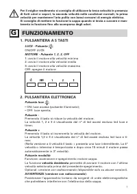
7 Per il miglior rendimento si consiglia di utilizzare la terza velocità in presenza di forti odori e vapori, la seconda velocità nelle condizioni normali, la prima velocità per mantenere l’aria pulita con bassi consumi di energia elettrica.Si consiglia di mettere in funzione la cappa quando si iniz...
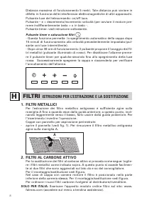
Page 10 - FILTRI; ISTRUZIONI PER L’ESTRAZIONE E LA SOSTITUZIONE; FILTRI AL CARBONE ATTIVO
8 Distanza massima di funzionamento 5 metri. Tale distanza può variare in difetto in funzione delle interferenze elettromagnetiche di altri apparecchi. Pulsante luce del telecomando: on/off luce. Pulsante – e + decremento/incremento velocità (per avviare il motore pre-mere indifferentemente tasto + ...
Page 11 - PANNELLO REMOVIBILE; ILLUMINAZIONE; MONTAGGIO E SOSTITUZIONE; LAMPADA A PLAFONIERA
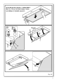
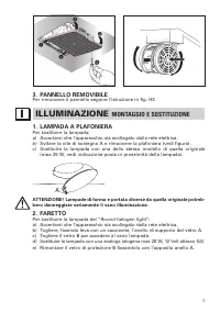
9 3. PANNELLO REMOVIBILE Per rimuovere il pannello seguire l’istruzione in fig. H3 ILLUMINAZIONE MONTAGGIO E SOSTITUZIONE I 1. LAMPADA A PLAFONIERA Per sostituire la lampada:a) Accertarsi che l’apparecchio sia scollegato dalla rete elettrica.b) Svitare la vite di sostegno A e rimuovere la plafoniera...
Page 12 - LAMPADA FLUORESCENTE
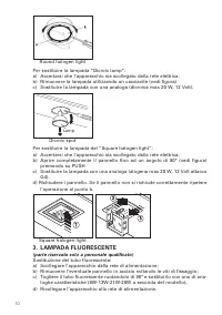
10 Round halogen light Per sostituire la lampada “Dicroic lamp”:a) Accertarsi che l’apparecchio sia scollegato dalla rete elettrica.b) Rimuovere la lampada utilizzando un cacciavite (vedi figura)c) Sostituire la lampada con una analoga (dicroica max 20 W, 12 Volt). Dicroic spot Lamp Per sostituire l...
Page 13 - MANUTENZIONE E PULIZIA; FILTRI ANTIGRASSO METALLICI
11 MANUTENZIONE E PULIZIA L Una costante manutenzione garantisce un buon funzionamento ed un buon rendimento nel tempo. Particolari attenzioni vanno rivolte ai filtri metallici an-tigrasso ed ai filtri al carbone attivo, infatti la pulizia frequente dei filtri e dei loro supporti garantisce che sull...
Page 14 - SICUREZZA; GARANZIA
12 SICUREZZA AVVERTENZE M L’impianto elettrico è munito di collegamento a terra secondo le norme di sicurezza internazionali; è inoltre conforme alle normative Europee sull’anti-disturbo radio. Non collegare l’apparecchio a condotti di scarico dei fumi prodotti dalla com-bustione (caldaie, caminetti...
Page 16 - INSTRUCTIONS BOOKLET; WARNINGS
14 GB INSTRUCTIONS BOOKLET WARNINGS A This instruction booklet must be kept together with the appliance for future reference. If the appliance is sold or consigned to other parties, check that the booklet is supplied with it, to ensure that the new user has the correct information on the operation o...
Page 17 - INSTALLATION; ELECTRICAL CONNECTIONS
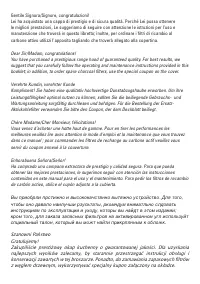
15 INSTALLATION C (Section reserved for qualified installers of the range hood) The distance between the hob and the lowest part of the rangehood is normally at least 65 cm (see figure C1). This distance is measuresd in the lowest part of the rangehood not operating at safety voltage. Based on this ...
Page 18 - OPERATION; FIVE BUTTON CONTROL PANEL
16 E RANGE HOOD WITH OUTSIDE DISCHARGE (exhaust) In this version, the fumes and steam from the kitchen are conveyed outside through an exhaust duct.The exhaust conveyor that protrudes from the upper part of the range hood must be connected to a duct that carries the fumes and steam outside. In this ...
Page 19 - ELECTRONIC CONTROL PANEL
17 2. ELECTRONIC CONTROL PANEL Light pushbutton - ON: light on (the pushbutton is lit); - OFF: light off; Pushbutton - Press to reduce motor speed Speed 1, 2 and 3 are indicated by the number of LEDs that light up (exclud-ing the light and the timer LEDs). Pushbutton + Press to increase motor speed ...
Page 20 - FILTERS; REMOVING AND REPLACING’S INSTRUCTIONS; LIGHTING; ASSEMBLY AND REPLACEMENT
18 FILTERS REMOVING AND REPLACING’S INSTRUCTIONS H 1. METAL FILTERS To remove the metal grease-trapping filter, simply pull the handle A until releasing it from the front guide; then tilt it slightly downwards, and slide it out of the rear guide. To reposition the filter, repeat the operation in the...
Page 22 - MAINTENANCE AND CLEANING; CLEANING THE OUTSIDE OF THE APPLIANCE
20 at point b. Square halogen light 3. FLUORESCENT TUBE (Section reserved for qualified installers) Replacing the fluorescent tube:a) Disconnect the device from the mains;b) Unscrew the fixing screws and remove the bottom panel;c) Remove the fluorescent tube, by rotating through 90°, and replace it ...
Page 23 - CLEANING THE INSIDE OF THE APPLIANCE; SAFETY WARNINGS
21 inevitably damage the finish of steel. The steel surface will be irrevocably damaged if the instructions above are not complied with. Keep these instructions together with the instructions for use of your hood. The manufacturer accepts no liability for any damage caused by non-compli-ance with th...
Page 25 - BEDIENUNGSANLEITUNG; HINWEISE
23 D BEDIENUNGSANLEITUNG HINWEISE A Diese Bedienungsanleitung muss unbedingt zusammen mit dem Gerät auf- bewahrt werden, um in Zukunft nachgeschlagen werden zu können. Sollte das Gerät verkauft bzw. einer anderen Person übergeben werden, muss die Bedienungsanleitung unbedingt mitgeliefert werden, da...
Page 27 - HAUBE MIT ABLUFTBETRIEB
25 - der blaue Draht ist für den Nullleiter, und - der braune Draht für die Phase bestimmt. Das Kabel darf auf keinen Fall mit heißen Teilen in Berührung kommen (über 70°C). - Am Netzkabel einen der Geräteleistung entsprechenden Stecker anbringen und diesen in eine Sicherheits- Steckdose stecken. Be...
Page 28 - ARBEITSWEISE; BEDIENFELD MIT 5 TASTEN; ELEKTRONISCHES BEDIENFELD
26 G ARBEITSWEISE 1. BEDIENFELD MIT 5 TASTEN LICHT – Taste ON/OFF LICHT MOTOR - Taste 1, 2, 3, OFF 1: startet den Motor mit Mindestdrehzahl 2: startet den Motor mit mittlerer Drehzahl 3: startet den Motor mit Höchstdrehzahl OFF: schaltet den Motor aus 2. ELEKTRONISCHES BEDIENFELD Lichtknopf • ON: Li...
Page 30 - BELEUCHTUNG; MONTAGE UND ERSATZ
28 NUR FÜR ITALIEN: Entsprechendes Formular von der Internetseite: www. falmec.com herunterladen (Zugriff über Pull-down-Menü). 3. ABSETZBARE TAFEL Folgen Sie den Anweisungen auf Abb. H3, um die Tafel zu entfernen. BELEUCHTUNG MONTAGE UND ERSATZ I 1. DECKENLAMPE Die Lampe wie folgt auswechseln:a) Da...
Page 31 - LEUCHTSTOFFLAMPE
29 Round halogen light Auswechseln der Lampe “Dicroic lamp”:a) Sich vergewissern, dass das Gerät nicht an das Stromnetz angeschlossen ist. b) Die Lampe mit Hilfe eines Schraubenziehers entfernen (siehe Abbildung)c) Die Lampe mit einer Lampe desselben Typs auswechseln (Kaltlichtlampe max. 20 W, 12 Vo...
Page 32 - WARTUNG UND REINIGUNG; REINIGUNG DER INNENFLÄCHE
30 WARTUNG UND REINIGUNG L Nur durch eine konstante Wartung ist ein einwandfreier Betrieb und eine lan-ge Lebensdauer der Dunstabzugshaube gewährleistet. Besondere Aufmerk-samkeit ist den Metall-Fettfiltern und den Aktivkohlefiltern zu schenken. Eine häufige Reinigung der Filter und deren Halter gew...
Page 33 - SICHERHEITSBESTIMMUNGEN; GARANTIE; Phase 1
31 SICHERHEITSBESTIMMUNGEN M Die elektrische Anlage ist mit einer Erdung ausgestattet, die den internationa- len Sicherheitsvorschriften entspricht; sie erfüllt außerdem die europäischen Entstörungsvorschriften. Das Gerät auf keinen Fall an die Ablassleitungen von Rauch, das durch Ver-brennung entst...
Page 34 - Phase 2
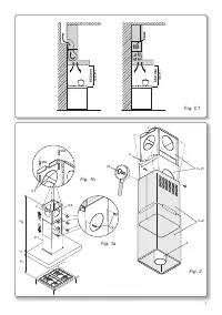
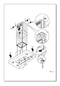
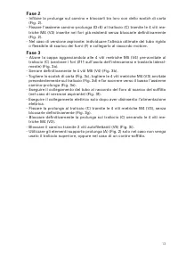
32 - Die Hängegerüste (C) und (C1) auf die gewünschte Höhe bringen (H2) und mit 8 gewindeformenden Schrauben (V2) befestigen (Abb.1a). - Das Hängegerüst (C) mit 4 Fischerdübeln Ø 8 mm und den jeweiligen Schrauben (V1) an der Decke anbringen (Abb.1b). Phase 2 - Das Verlängerungsstück in den Kamin ein...
Page 35 - LIVRET D’INSTRUCTIONS; AVERTISSEMENTS
33 F LIVRET D’INSTRUCTIONS AVERTISSEMENTS A Conserver cette notice avec l’appareil pour pouvoir la consulter en cas de besoin. Si l’appareil est vendu ou cédé à tiers, veiller à ce que la notice soit fournie en même temps pour que le nouvel utilisateur puisse avoir toutes les indications concernant ...
Page 36 - BRANCHEMENT ÉLECTRIQUE
34 CARACTÉRISTIQUES TECHNIQUES B Les données techniques de l’appareil sont reportées sur les plaques qui se trouvent à l’intérieur de la hotte (enlever les grilles métalliques pour voir l’étiquette. MONTAGE C (partie réservée au personnel qualifié pour le montage de la hotte) La distance entre la cu...
Page 38 - FONCTIONNEMENT; BOÎTIER DE COMMANDE À 5 TOUCHES
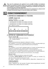
36 Pour que le rendement soit optimal, il est conseillé d’utiliser la troisième vitesse en présence d’odeurs fortes et de vapeurs, la deuxième vitesse dans des conditions normales et la première vitesse pour maintenir l’air propre en consommant peu d’énergie électrique. Il est conseillé d’allumer la...
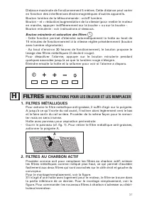
Page 39 - FILTRES; INSTRUCTIONS POUR LES ENLEVER ET LES REMPLACER; FILTRES MÉTALLIQUES; FILTRES AU CHARBON ACTIF
37 Distance maximale de fonctionnement 5 mètres. Cette distance peut varier en fonction des interférences électromagnétiques d’autres appareils. Bouton lumière de la télécommande : on/off lumière. Bouton – et + réduction/augmentation de la vitesse (pour mettre le moteur en marche, appuyer indifférem...
Page 40 - PANNEAU REMOVIBILE; ÉCLAIRAGE; MONTAGE ET REMPLACEMENT
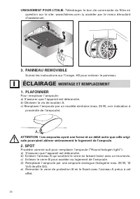
38 UNIQUEMENT POUR L’ITALIE: Télécharger le bon de commande du filtre en question sur le site: www.falmec.com (y accéder par le menu déroulant d’assistance). 3. PANNEAU REMOVIBILE Suivez les instructions sur l’image. H3 pour enlever le panneau. ÉCLAIRAGE MONTAGE ET REMPLACEMENT I 1. PLAFONNIER Pour ...
Page 41 - LAMPE FLUORESCENTE
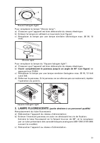
39 Round halogen light Pour remplacer la lampe “Dicroic lamp”:a) S’assurer que l’appareil est bien débranché du réseau électrique.b) Enlever la lampe en utilisant un tournevis (voir figure)c) Remplacer la lampe par une lampe similaire (dichroïque max. 20 W, 12 Volt). Dicroic spot Lamp Pour remplacer...
Page 42 - ENTRETIEN ET NETTOYAGE; FILTRES AU CHARBON ACTIF; NETTOYAGE INTÉRIEUR DE LA HOTTE
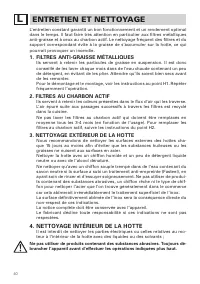
40 ENTRETIEN ET NETTOYAGE L L’entretien constant garantit un bon fonctionnement et un rendement optimal dans le temps. Il faut faire très attention en particulier aux filtres métalliques anti-graisse et à ceux au charbon actif. Le nettoyage fréquent des filtres et du support correspondant évite à la...
Page 43 - SÉCURITÉ
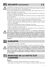
41 SÉCURITÉ AVERTISSEMENTS M L’installation électrique est dotée d’un branchement à la terre comme reporté dans les normes de sécurité internationales ; elle est par ailleurs conforme aux normes européennes sur les parasites radio. Ne pas relier l’appareil aux conduits d’évacuation des fumées dues à...
Page 45 - MANUAL DE INSTRUCCIONES; ADVERTENCIAS
43 E MANUAL DE INSTRUCCIONES ADVERTENCIAS A Es muy importante conservar este libro de instrucciones junto al aparato para cualquier consulta futura. Si el aparato tuviera que ser vendido o traspasado a otra persona, asegúrese que el libro vaya incluido, de modo que el nuevo usuario pueda ponerse al ...
Page 48 - FUNCIONAMIENTO; BOTONERA DE 5 TECLAS; BOTONERA ELECTRÓNICA
46 olores. G FUNCIONAMIENTO 1. BOTONERA DE 5 TECLAS LUZ – Pulsador Pulsado: la luz permanecerá siempre encendida. Sin pulsar: la luz permanecerá siempre apagada. MOTOR – Pulsador 1, 2, 3 OFF 1: pone en marcha el motor a la velocidad mínima. 2: pone en marcha el motor a la velocidad intermedia. 3: po...
Page 49 - FILTROS; INSTRUCCIONES PARA EXTRACCIÓN Y SUSTITUCIÓN; FILTROS DE CARBÓN ACTIVO
47 Distancia máxima de funcionamiento de 5 metros. Esta distancia puede variar en defecto en función de las interferencias electromagnéticas de otros aparatos. Luz pulsador del temando: ON/OFF Pulsador – y + disminución/incremento velocidad (para arrancar el motor pulsar indiferentemente pulsador + ...
Page 50 - PANEL DESPRENDIBLE; ILUMINACIÓN; MONTAJE Y SUSTITUCIÓN
48 filtro del sitio: www.falmec.com (acceda desde el menú al desplegable asistencia). 3. PANEL DESPRENDIBLE Para quitar el panel seguir las instrucciones fig. H3. ILUMINACIÓN MONTAJE Y SUSTITUCIÓN I 1. LÁMPARA Para sustituir la bombilla:a) Asegurarse que el aparato está desconectado de corriente elé...
Page 51 - MANTENIMIENTO Y LIMPIEZA
49 Round halogen light Para sustituir la lámpara dicróica:a) Asegurase que el aparato está desconectado de la red eléctricab) Quitar la lámpara utilizando un destornillador (ver figura)c) Sustituir la lámpara por una similar (dicroica max 20 W, 12 Volt) Dicroic Lamp Para sustituir la lámpara halógen...
Page 52 - SEGURIDAD
50 metálicos antigrasa y a los filtros de carbón activo, en efecto la limpieza fre-cuente de los filtros y de sus soportes garantiza que no se acumulen grasas, que son peligrosas por la facilidad de incendio, en la campana extractora. 1. FILTROS ANTIGRASA METÁLICOS Su función es retener las partícul...
Page 53 - GARANTÍA
51 No conectar el aparato a conductos de salida de humos derivados de combu-stión (calefacción, chimeneas, etc). Verificar que la tensión de la red eléctrica corresponde a la que indica la etiqueta localizada en el interior de la campana. La distancia mínima de seguridad desde la encimera a la campa...
Page 55 - àçëíêìäñàü èé ùäëèãìÄíÄñàà; åÖêõ èêÖÑéëíéêéÜçéëíà
53 RUS àçëíêìäñàü èé ùäëèãìÄíÄñàà åÖêõ èêÖÑéëíéêéÜçéëíà A é˜Â̸ ‚‡ÊÌÓ, ˜ÚÓ·˚ ‰‡ÌÌÓ êÛÍÓ‚Ó‰ÒÚ‚Ó ÔÓ ˝ÍÒÔÎÛ‡Ú‡ˆËË ı‡ÌËÎÓÒ¸ ‚ÏÂÒÚÂ Ò ‡ÔÔ‡‡ÚÛÓÈ ‰Îfl ‚ÓÁÏÓÊÌÓÈ ÌÂÓ·ıÓ‰ËÏÓÒÚË ÍÓÌÒÛθڇˆËË ‚ ·Û‰Û˘ÂÏ. èË ÔÓ‰‡Ê ÔË·Ó‡ ËÎË Ô‰‡˜Â Â„Ó ‰Û„ÓÏÛ ÎËˆÛ Í ÔË·ÓÛ Ó·flÁ‡ÚÂθÌÓ ‰ÓÎÊÌÓ ÔË·„‡Ú¸Òfl êÛÍÓ‚Ó‰ÒÚ‚Ó, ˜...
Page 56 - éëçéÇçõÖ áÄåÖóÄçàü; èéÑäãûóÖçàÖ ùãÖäíêéùçÖêÉàà
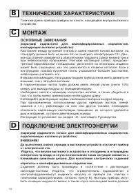
54 íÖïçàóÖëäàÖ ïÄêÄäíÖêàëíàäà B íıÌ˘ÒÍË ‰‡ÌÌ˚ ÔË·Ó‡ ÔË‚‰Ì˚ ̇ ˝ÚËÍÚÍ, ̇ıÓ‰fl˘ÈÒfl ‚ÌÛÚË ‚˚ÚflÊÌÓ„Ó ÛÒÚÓÈÒÚ‚‡. åéçíÄÜ C éëçéÇçõÖ áÄåÖóÄçàü (Ô‡‡„‡Ù ԉ̇Á̇˜Ì ‰Îfl Í‚‡ÎËÙˈËÓ‚‡ÌÌ˚ı ÒԈˇÎËÒÚÓ‚, ÏÓÌÚËÛ˛˘Ëı ‚˚ÚflÊÌÓ ÛÒÚÓÈÒÚ‚Ó) Расстояние между кухонной плитой и самой нижней точкой вытяжки , по ст...
Page 57 - Ö ÇõíüÜçéÖ ìëíêéâëíÇé ë
55 ·˚Ú¸ “Òڇ̉‡ÚÌÓ„Ó” ÚËÔ‡ Ò Û˜ÚÓÏ ÚÓ„Ó, ˜ÚÓ: - ÊÎÚÓ-ÁÎÌ˚È ÔÓ‚Ó‰ ‰ÓÎÊÌ ËÒÔÓθÁÓ‚‡Ú¸Òfl ‰Îfl Á‡ÁÏÎÌËfl, - „ÓÎÛ·ÓÈ ÔÓ‚Ó‰ ‰ÓÎÊÌ ËÒÔÓθÁÓ‚‡Ú¸Òfl ‰Îfl ÌÈڇθÌÓ„Ó ÔÓ‚Ó‰‡, - ÍÓ˘̂˚È ÔÓ‚Ó‰ ‰ÓÎÊÌ ËÒÔÓθÁÓ‚‡Ú¸Òfl ‰Îfl Ù‡Á˚, ¯ÌÛ Ì ‰ÓÎÊÌ Í‡Ò‡Ú¸Òfl ̇„Ú˚ı ˜‡ÒÚÈ, ËÏ˛˘Ëı ÚÏÔ‡ÚÛÛ ·ÓÎ 70°C. - ÛÒÚ‡ÌÓ‚ËÚ Ì‡ ¯ÌÛ ˝...
Page 58 - êÄÅéíÄ; èüíàäçéèéóçéÖ ìèêÄÇãÖçàÖ; äçéèäà ë ùãÖäíêéççõå ìèêÄÇãÖçàÖå
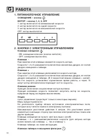
56 G êÄÅéíÄ 1. èüíàäçéèéóçéÖ ìèêÄÇãÖçàÖ éëÇÖôÖçàÖ – ÍÌÓÔ͇ åéíéê – ÍÌÓÔ͇ 1, 2, 3, OFF 1: ÏÓÚÓ ‚Íβ˜‡ÚÒfl ̇ ÏËÌËχθÌÓÈ ÒÍÓÓÒÚË 2: ÏÓÚÓ ‚Íβ˜‡ÚÒfl ̇ Ò‰ÌÈ ÒÍÓÓÒÚË 3: ÏÓÚÓ ‚Íβ˜‡ÚÒfl ̇ χÍÒËχθÌÓÈ ÒÍÓÓÒÚË OFF: ÏÓÚÓ ‚˚Íβ˜‡ÚÒfl. 2. äçéèäà ë ùãÖäíêéççõå ìèêÄÇãÖçàÖå ä·‚˯‡ ÓÒ‚Â˘ÂÌËfl - ON: ÓÒ‚Â˘Â...
Page 59 - îàãúíêõ; àçëíêìäñàà èé àáÇãÖóÖçàû à áÄåÖçÖ; åÖíÄããàóÖëäàÖ îàãúíêõ
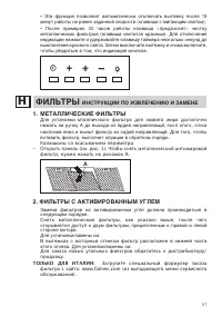
57 • ùÚ‡ ÙÛÌ͈Ëfl ÔÓÁ‚ÓÎflÂÚ ‡‚ÚÓχÚ˘ÂÒÍË ÓÚÍβ˜‡Ú¸ ‚˚ÚflÊÍÛ ÔÓÒΠ15 ÏËÌÛÚ ‡·ÓÚ˚ ̇ ‡Ì Á‡‰‡ÌÌÓÈ ÒÍÓÓÒÚË (Í·‚˯‡ Ò ÏË„‡˛˘ËÏ Ò‚ÂÚÓÏ). • èÓÒΠÔËÏÂÌÓ 30 ˜‡ÒÓ‚ ‡·ÓÚ˚ Í·‚˯‡ «Ô‰·„‡ÂÚ» ˜ËÒÚÍÛ ÏÂÚ‡Î΢ÂÒÍËı ÙËθÚÓ‚ (Í·‚˯‡ Ò‚ÂÚËÚÒfl ͇ÒÌ˚Ï). ÑÎfl ÓÚÍβ˜ÂÌËfl Ë̉Ë͇ˆËË Ì‡ÊÏËÚÂ Ë Û‰ÂÊË‚‡ÈÚ Í·‚...
Page 60 - éëÇÖôÖçàÖ; ìëíÄçéÇäÄ à áÄåÖçÄ; ЛАМПОЧКА
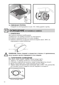
58 3. СМЕННАЯ ГРУППА Следуйте за инструкциями на рис . H3, чтобы удалять группу . éëÇÖôÖçàÖ ìëíÄçéÇäÄ à áÄåÖçÄ I 1. ЛАМПОЧКА Для замены лампочки необходимо : а ) убедиться , что прибор отключет от электросети ; б ) открутить крепежный винт А и снять плафон ; в ) заменить лампочку на другую такой же ...
Page 61 - ФЛУОРЕСЦЕНТНАЯ; óàëíäÄ à ìïéÑ; åÖíÄããàóÖëäàÖ îàãúíêõ Ñãü áÄÑÖêÜÄçàü ÜàêÄ
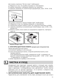
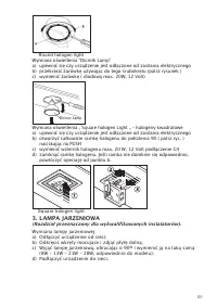
59 Для замены лампочки “Dicroic Lamp” необходимо : а ) Убедиться в том , что прибор отключен от электросети ; б ) извлечь лампочку с помощью отвертки ( см . рисунок ); в ) заменить лампочку на аналогичную ( дихроичную , макс . 20 Вт , 12 В ). Dicroic Lamp Для замены лампочки “Square halogen light” н...
Page 62 - ÅÖáéèÄëçéëíú
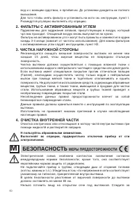
60 ‚Ó‰ Ë Ò ÏÓ˛˘ËÏ Ò‰ÒÚ‚ÓÏ, Ì Ô„Ë·‡fl Ëı. ÑÓ ÛÒÚ‡ÌÓ‚ÍË ‰ÓʉËÚÒ¸ Ëı ÔÓÎÌÓ„Ó ‚˚Ò˚ı‡ÌËfl. ÑÎfl ÚÓ„Ó ˜ÚÓ·˚ ÒÌflÚ¸ ÙËÎ¸Ú Ë ÛÒÚ‡ÌÓ‚ËÚ¸ ̇ ÏÒÚÓ ÒÏ. ËÌÒÚÛ͈ËË, ÔÛÌÍÚ I. êÍÓÏ̉ÛÚÒfl „ÛÎflÌÓ ‚˚ÔÓÎÌflÚ¸ ˝ÚÛ ÓÔ‡ˆË˛. 2. îàãúíêõ ë ÄäíàÇàêéÇÄççõå ìÉãÖå è‰Ì‡Á̇˜Ì˚ ‰Îfl Á‡‰Ê‡ÌËfl Á‡Ô‡ıÓ‚, ÔËÒÛÚÒÚ‚Û˛˘Ëı ‚ ‚ÓÁ‰Ûı, ÍÓÚ...
Page 63 - ÉÄêÄçíàà; Этап
61 ÙËÚ˛Ìˈ‡ÏË: Ô„ÂÚÓ χÒÎÓ ÏÓÊÂÚ Á‡„ÓÂÚ¸Òfl. - ì·Â‰ËÚÂÒ¸ ‚ ÚÓÏ, ˜ÚÓ ‚ ÔÓÏ¢ÂÌËË ËÏÂÂÚÒfl ‰ÓÒÚ‡ÚӘ̇fl ‚ÂÌÚËÎflˆËfl, ÂÒÎË ‚˚ÚflÊ͇ ËÒÔÓθÁÛÂÚÒfl ÒÓ‚ÏÂÒÚÌÓ Ò ‰Û„ËÏË ÔË·Ó‡ÏË, ‡·ÓÚ‡˛˘ËÏË Ì‡ „‡Á ËÎË ‰Û„ÓÏ „Ó˛˜ÂÏ. - ç Á‡ÊË„‡ÈÚ ÓÚÍ˚Ú˚È Ó„Ó̸ ÔÓ‰ ‚˚ÚflÊÍÓÈ. - ç ÔÓ‰Íβ˜‡ÈÚ ÔË·Ó Í ÚÛ·‡Ï, ÓÚ‚Ó‰fl...
Page 65 - OSTRZE
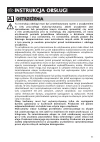
63 PL INSTRUKCJA OBS Ł UGI INSTRUKCJA OBS Ł UGI OSTRZE Ż ENIA OSTRZE Ż ENIA A Ta instrukcja obs ł ugi musi by ć przechowywana razem z urz ą dzeniem w celu przysz ł ego wykorzystywania. Je ż eli urz ą dzenie jest sprzedawane lub przesy ł ane innym stronom, sprawdzi ć , czy wraz z nim przekazywana jes...
Page 68 - PULPIT STEROWANIA PI
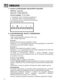
66 G OBS Ł UGA OBS Ł UGA 1. PULPIT STEROWANIA PI Ę CIOPRZYCISKOWY Ś WIAT Ł O – przycisk Naci ś ni ę ty: ś wiat ł o w łą czone Zwolniony: ś wiat ł o wy łą czone Przycisk SILNIKA – 1, 2, 3, OFF 1: uruchamia silnik z minimaln ą pr ę dko ś ci ą 2: uruchamia silnik ze ś redni ą pr ę dko ś ci ą 3: urucham...
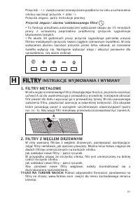
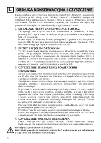
Page 69 - FILTRY; INSTRUKCJE WYJMOWANIA I WYMIANY; GLEM DRZEWNYM
67 Przyciski – i +: zwi ę kszanie/zmniejszanie pr ę dko ś ci (w celu uruchomienia silnika nacisn ąć przycisk + albo -). Przycisk zegara: patrz instrukcje poni ż ej. Przycisk zegara i alarmu ʻ zablokowanego filtra ʼ • Ta funkcja umo ż liwia automatyczne wy łą czanie okapu po 15 minutach pracy z ustaw...
Page 70 - MONTA; ARÓWKA
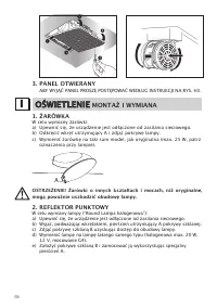
68 3. PANEL OTWIERANY ABY WYJ ĄĆ PANEL PROSZ Ę POST Ę POWA Ć WED Ł UG INSTRUKCJI NA RYS. H3. O Ś WIETLENIE O Ś WIETLENIE MONTA Ż I WYMIANA I 1. Ż ARÓWKA W celu wymiany ż arówki: a) Upewni ć si ę , ż e urz ą dzenie jest od łą czone od zasilania sieciowego. b) Odkr ę ci ć wkr ę t utrzymuj ą cy A i zdj...
Page 73 - GWARANCJA
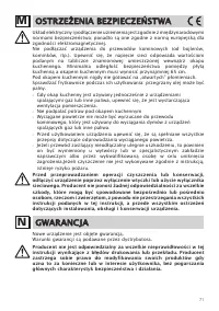
71 OSTRZE Ż ENIA BEZPIECZE Ń STWA OSTRZE Ż ENIA BEZPIECZE Ń STWA M Uk ł ad elektryczny i pod łą czenie uziemienia jest zgodnie z mi ę dzynarodowymi normami bezpiecze ń stwa; ponadto s ą one zgodne z norm ą europejsk ą dla zgodno ś ci elektromagnetycznej. Nie pod łą cza ć urz ą dzenia do przewodów ko...
Page 74 - Krok 1
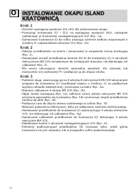
72 O INSTALOWANIE OKAPU ISLAND INSTALOWANIE OKAPU ISLAND KRATOWNIC Ą KRATOWNIC Ą Krok 1 - Okre ś li ć wymagan ą wysoko ść (H1=65) dla umieszczenia okapu - Przesun ąć kratownice (C) i (C1) na wymagan ą wysoko ść (H2), nast ę pnie zablokowa ć je 8 wkr ę tami samogwintuj ą cymi (V2) (Rys. 1a). - Zamoco...
Page 75 - Note
Page 79 - Condizioni di garanzia
Condizioni di garanzia 1) L’apparecchio è garantito dalla Casa costruttrice Falmec S.p.A (www.falmec.com) per un periodo di 24 mesi dalla data del suo acquisto comprovata da ricevuta fiscale o altro documento reso fiscalmente obbli-gatorio. 2) La garanzia sarà prestata con la sostituzione o riparazi...
Page 80 - La presente garanzia è valida solo per l’Italia; (Guarantee conditions are valid only for; CERTIFICATO DI GARANZIA; FALMEC
IMPORTANTE! La presente garanzia è valida solo per l’Italia (Guarantee conditions are valid only for Italy) . Questo certificato di garanzia non deve essere spedito, ma conservato con la rice-vuta fiscale, o altro documento reso fiscalmente obbligatorio, che comprovi la data d’acquisto della cappa.I...