Defiant DK02A-MB - User Manual
Defiant DK02A-MB Electronic Deadbolt – User Manual, read for free online in PDF format. We hope this helps you resolve any issues you may have. If you have further questions, please contact us through the contact form.


Warranty
LIMITED LIFETIME FOR MECHANICAL AND 1 YEAR FOR ELECTRONICAL WARRANTY
The retailer of this product, hereby warrants, subject to the conditions set forth below, that it will either repair or
replace, at its option, this product if it proves to be defective by reason of improper workmanship or materials
within the original purchaser’s lifetime. In order to obtain repairs or replacement under this limited warranty
you must bring this product to the retailer’s store in which you bought it.
Original purchaser: This limited warranty is limited to the original purchaser at retail of this product from retailer.
Except to the extent prohibited by applicable law, no other warranties, whether express or implied, including
the warranties of merchantability and fitness for a particular purpose, shall apply to this product. Under no
circumstances shall retailer be liable for consequential or incidental damages in connection with this product. To
the extent retailer is prohibited by applicable law from excluding implied warranties, the duration of such implied
warranties which are not excludable shall be the original purchaser’s lifetime. Some states do not allow the
limitation on how long an implied warranty lasts, so the above limitation on the duration of implied warranties
which are not excludable, if any, may not apply to you. Some states do not allow the exclusion or limitation
of incidental or consequential damages, so the above limitation or exclusion of incidental or consequential
damages may not apply to you. Retailer neither assumes nor authorizes any representative or other person to
assume for it any obligation or liability other than such as is expressly set forth herein. This limited warranty
gives you specific legal rights, and you may also have other rights which vary from state to state.
Questions, problems, missing parts? Before returning to the store,
call Defiant Customer Service
8 a.m. - 7 p.m., EST, Monday-Friday, 9 a.m. - 6 p.m., EST, Saturday
1-866-308-3976
HOMEDEPOT.COM
INSTALLATION GUIDE
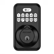
FINGERPRINT KEYPAD DEADBOLT
KPDKS02ADK02A
Rev. 1.0
THANK YOU
We appreciate the trust and confidence you have placed in Defiant through the purchase of this fingerprint keypad
deadbolt. We strive to continually create quality products designed to enhance your home. Visit us online to see our full
line of products available for your home improvement needs. Thank you for choosing Defiant!
1
Preparing the door and checking dimensions
Measure to confirm that the hole in the door is 2-1/8 in. (54 mm).
Measure to confirm that the backset is either 2-3/8 in. or 2-3/4 in. (60 or 70 mm).
Measure to confirm that the hole in the door edge is 1 in. (25 mm).
Measure to confirm that the door is 1-3/8 in. to 2 in. (35 mm to 50 mm) thick.
2
Installing the latch and strike
Hold the latch (C) in front of the door hole, with the latch face flush against the door edge. No
adjustment is required if slotted hole is centered (backset 2-3/8 in.); Rotate and pull backwards the
latch to extend, then rotate it back as shown if slotted hole is not centered (backset 2-3/4in.).
2a. Installing latch and strike - door edge chiseled
Install the latch in door edge hole directly with latch screws (K) if your door edge is chiseled.
3
Installing exterior assembly
Route the power cable (M) below the latch.
Install exterior assembly (B) and send the power cable through the bottom horizontal slot in the
mounting plate (D).
Secure the mounting plate with the mounting screws (E).
4
Installing interior assembly
Remove the battery cover (G).
Connect the power cable (M) and ensure tight cable connection.
Rotate the thumb turn in vertical position and install the interior assembly (F).
Test the thumb turn for smooth rotation. If thumb turn doesn’t rotate, repeat last step, making sure
the thumb turn in vertical position.
Secure the interior assembly with the supplied screws (H).
5
Detecting left/right hand door installation
Reset the lock to teach the lock the orientation of the door.
While the door is OPEN and UNLOCKED, load three AA batteries into the interior assembly.
Press and hold the Reset button on the interior assembly using the reset tool (O) included in package.
Load the last battery and keep holding the reset button for at least 3 seconds, until you hear the
sound of “beep”. The latch bolt will extend to learn the orientation of the door.
Safety Information
Read the precautions and instructions in this manual before installing and using this lock. Save this
manual for future reference.
Do not attempt to disassemble any internal components of the lockset. Doing so will void the limited
warranty.
Do not drop or hit the lockset. Too much shock may result in permanent damage.
Do not use pins or sharp objects to press the keypad and fingerprint sensor.
Always create a backup of information you wish to keep (Master Code, User Codes, etc.).
Promptly change the master code before operating this lockset.
Restrict access to your lock’s interior assembly and routinely check your settings to ensure they have
not been altered without your knowledge.
Care and Cleaning
Remove locks, or do not install locks, prior to painting your door.
Periodically clean with mild soap and a soft cloth only.
Do not use any abrasives or chemical products containing alcohol, benzene, or acids, and avoid using
sharp or abrasive objects to clean this lockset.
Do not allow any water or liquids into the lockset during installation.
This lockset is designed to provide the highest standard of product quality and performance. Care
should be taken to ensure a long-lasting finish. When cleaning is required use a soft, damp cloth.
Using lacquer thinner,caustic soaps,abrasive cleaners, or polishes could damage the coating and
result in tarnishing.
TOOLS REQUIRED
PACKAGE CONTENTS
Chiseled
Not
Chiseled
Insert a flat head screwdriver into latch slot and rotate to test if deadbolt works smoothly.
Install strike (J) in the door frame with strike screws (L), and in order to maintain BHMA Grade 3,
you must install the reinforcement plate (I).
2b. Installing latch and strike - door edge not chiseled
Use a flat head screwdriver to remove rectangular face and rotate off part of the latch face, then install
drive-in collar (N) if your door edge is not chiseled. Then install latch in door with wood block and hammer.
1-3/8 in. to 2 in.
35 mm to 50 mm
2-3/8 in. or 2-3/4 in.
60 or 70 mm
Backset
2-1/8 in.
54 mm
1 in.
25 mm
Installation
Installation (continued)
Installation (continued)
Installation (continued)
C
K
1
2
3
4
N
L
J
I
(optional)
latch slot
IMPORTANT:
Make sure hole in
door frame is drilled a minimum of
1 in. (25.4 mm) deep.
IMPORTANT:
Before installation,
make sure the latch is fully
retracted (in the unlocked position).
NOTE:
Before beginning installation of product, make sure all parts are present. If any part is missing or
damaged, do not attempt to assemble, install or operate the product. Call the Customer Service Team at
1-866-308-3976 or visit www.homedepot.com.
IMPORTANT:
Do not load batteries until lock is completely installed
.
IMPORTANT:
Lock knob will only rotate to the lock position in either the clockwise or
counterclockwise direction based on your door handing, not both.
IMPORTANT:
This step is required and crucial for the lock to operate properly.
IMPORTANT:
For best results, use new, non-rechargeable alkaline batteries only.
Unlocked
Parallel to the door edge.
Unlocked
B
M
D
E
Horizontal Torque Blade
F
D
M
G
H
Unlocked
Reset tool
O
See the
User Guide
for additional information.
WARNING:
Do not use electric drill or electric screwdriver to tighten screws.
Pre-Installation
A
B
C
D
E
F
G
H
J
K
I
L
N
M
O
Part Description
Part Description
A
Backup Key
H
Screws
B
Exterior Assembly
I
Reinforcement plate
C
Latch
J
Strike
D
Mounting Plate
K
Latch Screws (21 mm)
E
Mounting Screws
L
Strike Screws (38 mm)
F
Interior Assembly
M
Power Cable
G
Battery Cover
N
Drive-in Collar
O
Reset Tool
2-3/4 in.
70 mm
2-3/8 in.
60 mm
Slotted hole
1
3
2
IMPORTANT:
Up arrow
needs to face up on latch.
"Loading the manual" means you need to wait until the file loads and becomes available for online reading. Some manuals are very large, and the time they take to appear depends on your internet speed.
Was this manual helpful?
About this manual
- Brand
- Defiant
- Model
- DK02A-MB
- Document type
- User Manual
- Category
- Electronic Deadbolt
- Language(s)
- English, Spanish
- Pages
- 4
- File size
- 8.6 MB
- Format