Page 3 - ENGLISH; Contents; Page
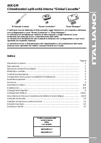
GB - 1 4 0 K Q MSplit system “Global cassette” indoor unit ENGLISH IR Remote Control “Room Controller” “Zone Manager” The unit can be used with infrared Remote Control, with the Carrier “RoomController” or “Zone Manager”.Infrared control installation instructions are contained in the unit instructio...
Page 4 - Dimensions and weight; Unit
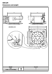
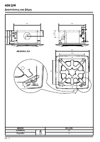
4 0 K Q M GB - 2 Dimensions and weight 40KQM 012, 015 Unit 19 Frame / Grille assembly 3 kg 575 298 120 225 280 56 52 91 575 158 720 550 515 Ø 150 Ø 70 50 30 Ø 25 40KQM012, 015
Page 5 - Table IV: Components required for a complete installation; Technical data; Table I: Nominal data; Table III: Operating limits
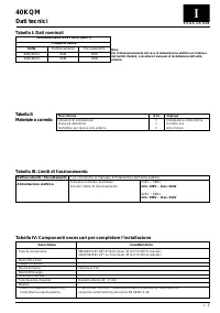
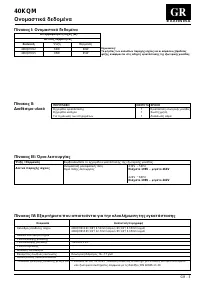
4 0 K Q M GB - 3 E N G L I S H Table IV: Components required for a complete installation Name Specification Connection pipe 40KQM012 Ø (3/8”) 9.52mm (Gas) / Ø (1/4”) 6.35mm (Liquid)40KQM015 Ø (1/2”) 12.7mm (Gas) / Ø (1/4”) 6.35mm (Liquid) Wall sleeve — Wall cap — Finishing tape PVC film Fastening ta...
Page 6 - Unit installation; General information; Choosing the installation site
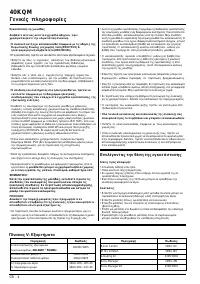
4 0 K Q M GB - 4 Unit installation Read this instruction manual thoroughly before startinginstallation. • This unit complies with the low-voltage (EEC/73/23) and electromagnetic compatibility (EEC/ 89/336) directives. • Installation must be carried out by qualified personnel. • Follow all current na...
Page 8 - Installation
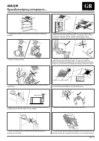
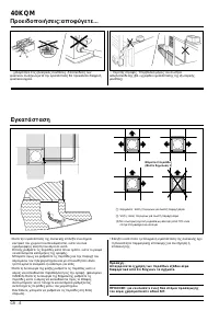
4 0 K Q M GB - 6 Max. 2 louvres closed (see Note 3) Installation Warnings: avoid... ... unnecessary turns and bends in connection pipes (seeinstallation manual of outdoor unit).Excessive connection pipe length (see installation manual ofoutdoor unit). ... slack on electrical connections.... disconne...
Page 9 - Prior to installation
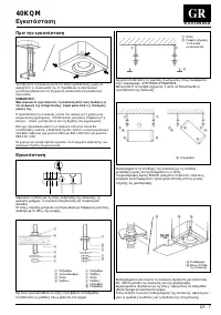
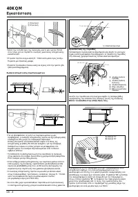
GB - 7 4 0 K Q M E N G L I S H Prior to installation It is advisable to place the unit as close as possible to theinstallation site before removing it from the packaging. The grillepanel and the remote control are separately packed for maximumprotection. IMPORTANT:Do not lift the unit by the condens...
Page 11 - Flaring the end of pipes; Refrigerant connections
GB - 9 4 0 K Q M E N G L I S H IMPORTANT:During the unit installation make first refrigerant connectionsand then electrical connections. If unit is uninstalled firstdisconnect electrical cables, then refrigerant connections. Refer to the outdoor unit installation manual for tube sizing,and limitatio...
Page 12 - Electrical connections; SYSTEM CONFIGURATION
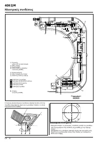
4 0 K Q M GB - 10 Electrical connections Condenser(under main terminalboard) Ground connectionscrews GMC board (inverter) Outdoor unit connectionterminal board Transformer Holes for fixing panel inposition Emergency push-button Fan connectorLED/RECEIVER connectorFloat connectorPump connectorLouverco...
Page 13 - Cable passage
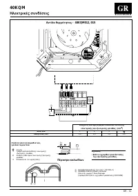
4 0 K Q M GB - 11 E N G L I S H Electrical connections Heat pump - 40KQM012, 015 1 2 3 1 2 3 1 10 80 Notes:• See outdoor unit installation manual. Terminal box legend, all models Earth 1 Live connection indoor/outdoor unit 2 Neutral connection indoor/outdoor unit 3 Communication (high voltage) Cable...
Page 14 - Fresh air renewal and conditioned air supply to an adjacent room; Air intake grille
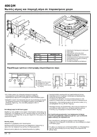
4 0 K Q M GB - 12 120 105 49 Ø A 216 B Ø A Ø C Fresh air renewal and conditioned air supply to an adjacent room Model 40KQM012, 015 Ø A mm 150 B mm 120 Ø C mm 70 Duct connection flange Clip 6 mm neoprene gasket Insulated flexible duct Fresh air intake Conditioned air supply to anadjacent room Polyst...
Page 15 - Fresh air renewal; Operating test
GB - 13 4 0 K Q M E N G L I S H I n c a s e o f t w o l o u v r e s c l o s e d , t h e f r e s h a i r f l ow t owa r d s t h e a d j a c e n t r o o m i s 5 0 % h i g h e r c o m p a r e d w i t h o n l y o n e l o u v r ec l o s e d ( w i t h e q u a l s t a t i c ex t e r n a l p r e s s u r e )...
Page 16 - Address selector and fault code; Address selector; Fault code
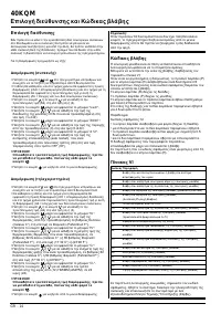
4 0 K Q M GB - 14 Address selector and fault code Address selector If you are installing two indoor units in the same room and you wantthem to operate in independent mode, it is necessary to assigneach unit its own address so that each unit can operate via its ownremote control. For configuration, p...
Page 17 - Guide for the owner; Unit warning lights and guide for the owner; Button T: “EMERGENCY”
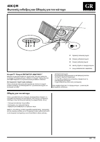
GB - 15 4 0 K Q M E N G L I S H Guide for the owner When installation and tests are completed explain the Operationand Maintenance Manual to the owner, with par ticular attention tothe main operating modes of the air conditioner, such as: • Turning the unit on and off. • Functions of the remote cont...
Page 18 - ALIANO; Indice; Pagina
I - 1 4 0 K Q MClimatizzatori split unità interna “Global Cassette” IT ALIANO IR Remote Control “Room Controller” “Zone Manager” L'unità può essere abbinata al telecomando raggi infrarossi o al comando a distanzacon collegamento a cavo “Room Controller” o “Zone Manager”.Le istruzioni di installazion...
Page 19 - Dimensioni e masse; Unità
4 0 K Q M I - 2 Dimensioni e masse 40KQM 012, 015 Unità 19 Gruppo cornice / griglia 3 kg 575 298 120 225 280 56 52 91 575 158 720 550 515 Ø 150 Ø 70 50 30 Ø 25 40KQM012, 015
Page 20 - Tabella IV: Componenti necessari per completare l'installazione; Dati tecnici; Tabella I: Dati nominali; Tabella III: Limiti di funzionamento
4 0 K Q M I - 3 I TA L I A N O Tabella IV: Componenti necessari per completare l'installazione Descrizione Caratteristiche Tubo di connessione 40KQM012 Ø (3/8”) 9.52mm (Gas) / Ø (1/4”) 6.35mm (Liquido) 40KQM015 Ø (1/2”) 12.7mm (Gas) / Ø (1/4”) 6.35mm (Liquido) Manicotto a muroCappuccio a muroNastro ...
Page 21 - Installazione dell'unità; Avvertenze generali; Scelta del luogo di installazione
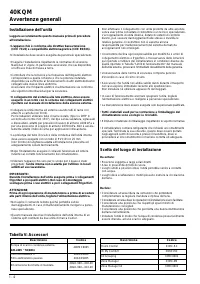
4 0 K Q M I - 4 Installazione dell'unità Leggere accuratamente questo manuale prima di procedereall’installazione. • L’apparecchio è conforme alle direttive bassa tensione (CEE 73/23) e compatibilità elettromagnetica (CEE 89/336). • L’installazione deve essere eseguita da personale specializzato. • ...
Page 23 - Installazione
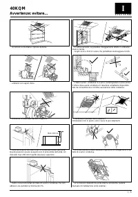
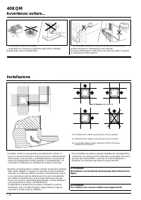
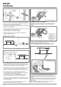
4 0 K Q M I - 6 Max 2 chiusure (vedi Nota 3) Avvertenze: evitare... Installazione • Per consentire una rapida e agevole installazione e manutenzione, controllare che nella posizione prescelta sia possibile rimuovere ipannelli del controsoffitto o, nel caso di controsoffittature inmuratura sia comunq...
Page 24 - Prima dell'installazione
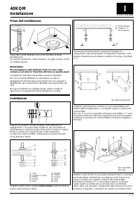
I - 7 4 0 K Q M I TA L I A N O Prima dell'installazione Traspor tare l'unità imballata il più vicino possibile al luogod'installazione.Per ulteriore protezione, il telecomando e la griglia vengono forniticon imballi separati. IMPORTANTE:Non maneggiare l'unità mediante il tubo di scarico dellacondens...
Page 26 - Connessione del tubo all'unità; Collegamenti frigoriferi
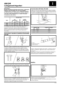
I - 9 4 0 K Q M I TA L I A N O IMPORTANTE:Durante l'installazione dell'unità eseguire prima i collegamentifrigoriferi e poi quelli elettrici. Nel caso di smontaggioscollegare prima i cavi elettrici e poi i collegamenti frigoriferi. Per dimensionamento e limiti (dislivello, lunghezza tubazioni,curve ...
Page 27 - Collegamenti elettrici; CONFIGURAZIONE DEL SISTEMA
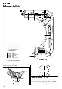
4 0 K Q M I - 10 Collegamenti elettrici CONFIGURAZIONE DEL SISTEMA • Effettuare prima il collegamento elettrico tra le due unità e successivamente il collegamento alla rete di alimentazione. Assisurarsi che il collegamento alla rete elettrica sia effettuato attraverso un interruttore onnipolare con ...
Page 28 - Passaggio cavi
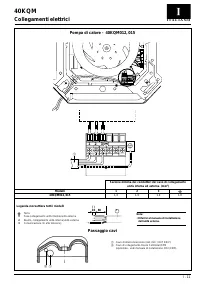
4 0 K Q M I - 11 I TA L I A N O Collegamenti elettrici Pompa di calore - 40KQM012, 015 Note: • Riferirsi al manuale di installazione dell'unità esterna. 1 2 3 1 2 3 1 10 80 Legenda morsettiera tutti i modelli Terra 1 Fase collegamento unità interna/unità esterna 2 Neutro, collegamento unità interna/...
Page 29 - Griglia di ripresa aria; Aria esterna di rinnovo e mandata aria trattata in locale attiguo
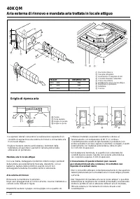
4 0 K Q M I - 12 120 105 49 Ø A 216 B Ø A Ø C • Le aperture laterali consentono la realizzazione separata di un condotto di aspirazione aria esterna di rinnovo e di mandata ariain un locale attiguo. • Togliere l'isolante esterno anticondensa, delimitato dalla fustellatura ed asportare i pannelli in ...
Page 30 - Diagramma di mandata aria verso locale attiguo: una aletta chiusa; Collaudo funzionale
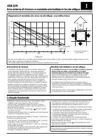
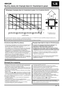
I - 13 4 0 K Q M I TA L I A N O Aria esterna di rinnovo e mandata aria trattata in locale attiguo Diagramma di mandata aria verso locale attiguo: una aletta chiusa Aria esterna di rinnovo • Il ventilatore ausiliario per l'aspirazione dell'aria esterna deve essere alimentato separatamente e comandato...
Page 31 - Selettore di indirizzo e codice d'errore; Selettore di indirizzo
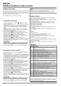
4 0 K Q M I - 14 Selettore di indirizzo e codice d'errore Selettore di indirizzo Se state installando due unità interne nello stesso locale e voleteche operino in modo indipendente, è necessario che diate ad ogniunità il suo indirizzo in modo che ognuna possa essere messa infunzione tramite il relat...
Page 32 - Indicatori luminosi e guida per l'utente
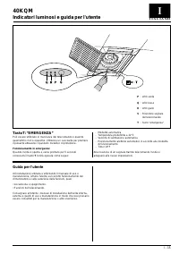
I - 15 4 0 K Q M I TA L I A N O Guida per l'utente Ad installazione ultimata e utilizzando il manuale di uso emanutenzione, istruire l'utente sul corretto funzionamento delclimatizzatore e sulla selezione delle funzioni, quali: • Accensione e spegnimento.• Funzioni del telecomando. Consegnare all'ut...
Page 33 - FRANÇAIS; Sommaire
F - 1 4 0 K Q MClimatiseur split unité intérieure “Global Cassette” FRANÇAIS IR Remote Control “Room Controller” “Zone Manager” L’unité peut être accompagnée de télécommande à rayons infrarouges, decommande à distance avec raccordement par fil au “Room Controller” ou “ZoneManager”.Les Instructions d...
Page 34 - Dimensions et poids; Unité
4 0 K Q M F - 2 Dimensions et poids 40KQM 012, 015 Unité 19 Groupe cadre / grille 3 kg 575 298 120 225 280 56 52 91 575 158 720 550 515 Ø 150 Ø 70 50 30 Ø 25 40KQM012, 015
Page 35 - Tableau IV: Composants requis pour une installation complète; Données techniques; Tableau I: Caractéristiques nominales; Tableau III: Limites de fonctionnement
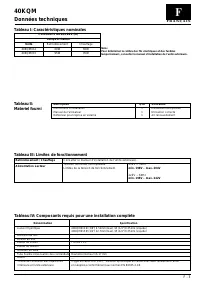
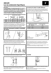
4 0 K Q M F - 3 F R A N Ç A I S Tableau IV: Composants requis pour une installation complète Dénomination Spécification Liaison frigorifique 40KQM012 Ø (3/8”) 9.52mm (Gaz) / Ø (1/4”) 6.35mm (Liquide)40KQM015 Ø (1/2”) 12.7mm (Gaz) / Ø (1/4”) 6.35mm (Liquide) Manchon au murDouille au murRuban de finit...
Page 36 - Installation de l'unité; Generalités; Le choix de l'emplacement; Tableau V: Accessoires
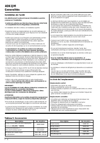
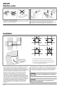
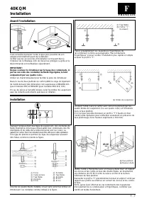
4 0 K Q M F - 4 Installation de l'unité Lire attentivement le présent manuel d’installation avant decommencer l’installation. • L’unité est conforme aux Directives Basse Tension (CEE/73/23) et Compatibilité Electro-Magnétique (CEE/89/336). • L'installation doit être confiée à un installateur qualifi...
Page 41 - Connexion du tube à l'unité intérieure; Les raccordements frigorifiques
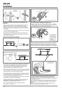
F - 9 4 0 K Q M F R A N Ç A I S IMPORTANT:Lors de l’installation de l’unité, effectuer d’abord les connexionsdu réfrigérant puis les connexions électriques. Lors de sadésinstallation, débrancher d’abord les câbles électriques puisles connexions du réfrigérant. Pour connaître le diamètre desconduites...
Page 42 - Les raccordements électriques; CONFIGURATION DU SYSTEME
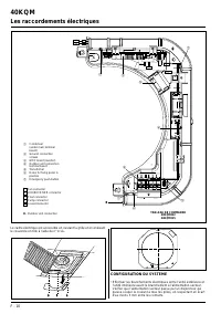
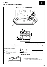
4 0 K Q M F - 10 Les raccordements électriques CONFIGURATION DU SYSTEME • Effectuer les branchements électriques entre l’unité extérieure et l’unité intérieure avant le branchement à l’alimentation secteur.Vérifier que l’alimentation secteur passe par un disjoncteur quipuisse couper le courant à tou...
Page 43 - Passage des câbles
4 0 K Q M F - 11 F R A N Ç A I S Les raccordements électriques Pompe à chaleur - 40KQM012, 015 1 2 3 1 2 3 1 10 80 Notes: • Voir le manuel d'installation de l'unité extérieure. Légende du bornier, tous modèles Terre 1 Fil de connexion entre l’unité intérieure et l’unitéextérieure 2 Neutre, connexion...
Page 44 - Grille de prise d’air
4 0 K Q M F - 12 120 105 49 Ø A 216 B Ø A Ø C Entrée du tuyau Collier de serrage Joint au Néoprène de 6 mm Gaine souple avec isolation Prise d'air neuf Distribution air en locale contigu Membrane en polystyrène Déflecteur Cadre Les renouvellements d'air et refoulement air traité dans une pièce conti...
Page 45 - Les renouvellements d’air; Test de fonctionnement
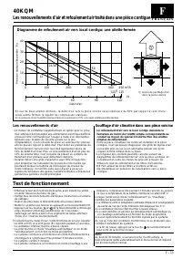
F - 13 4 0 K Q M F R A N Ç A I S E n c a s d e d e u x a i l e t t e s fe r m é e s, l e d é b i t d ’ a i r ve r s l a p i è c e vo i s i n e s e ra s u p é r i e u r e d u 5 0 % p a r ra p p o r t à c e l u i d ’ u n es e u l e a i l e t t e fe r m é e ( à é g a l i t é d e c o m p r e s s i o n s...
Page 46 - Sélecteur d’adresse et code de défaut; Sélecteur d’adresse
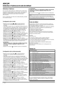
4 0 K Q M F - 14 Sélecteur d’adresse et code de défaut Sélecteur d’adresse Pour que deux unités intérieures installées dans la même piècefonctionnent indépendamment l’une de l’autre, il est nécessaired’attribuer à chacune d’elles sa propre adresse de manièrequ’elles puissent fonctionner par le biais...
Page 47 - Guide de l’utilisateur; Voyants et guide de l’utilisateur; Touche T: “Touche de SECOURS”
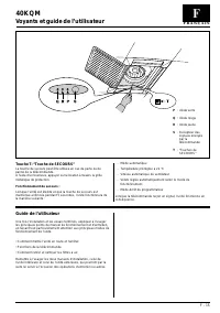
F - 15 4 0 K Q M F R A N Ç A I S Guide de l’utilisateur Une fois l’installation et les essais terminés, expliquer à l’usagerles principaux points du manuel de fonctionnement et d’entretien,en faisant tout particulièrement attention aux principaux modes defonctionnement de l’unité. • Comment mettre l...
Page 48 - DEUTSCH; Inhalt; Seite
D - 1 4 0 K Q MSplit System-Kassettengeräte DEUTSCH IR Remote Control “Room Controller” “Zone Manager” Das Gerät kann mit der Infrarot-Fernbedienung, mit der verkabelten FernbedienungRoom Controller oder “Zone Manager” verwendet werden.Die Installationsanweisungen für die Infrarot-Fernbedienung sind...
Page 49 - Maße und Gewichte; Gerät
4 0 K Q M D - 2 Maße und Gewichte 40KQM 012, 015 Gerät 19 Rahmen-/Gitter-Baugruppe 3 kg 575 298 120 225 280 56 52 91 575 158 720 550 515 Ø 150 Ø 70 50 30 Ø 25 40KQM012, 015
Page 50 - Technische Daten
4 0 K Q M D - 3 D E U T S C H Tabelle IV: Notwendige Komponente zur Vollendung der Installation Bezeichnung Spezifikation Verbindungsschlauch 40KQM012 Ø (3/8”) 9.52mm (Gas) / Ø (1/4”) 6.35mm (Flüssigkeit) 40KQM015 Ø (1/2”) 12.7mm (Gas) / Ø (1/4”) 6.35mm (Flüssigkeit) WandmuffeWandkappe Endband PVC-F...
Page 51 - Allgemeine Hinweise; Wahl des Installationsorts
4 0 K Q M D - 4 Geräte-Installation Dieses Handbuch sorgfältig durchlesen, ehe mit derInstallation begonnen wird. • Das Gerät entspricht der Niederspannungs- Richtlinie (EEC 73/23) und der Richtlinie über elektromagnetischeVerträglichkeit (EEC/89/336). • Die Installation ist von einer Fachfirma durc...
Page 54 - Vor der Installation
D - 7 4 0 K Q M D E U T S C H Vor der Installation Die Geräte in der Ver packung so nahe wie möglich zumInstallationsor t bringen. Das Gitter und die Fernbedienung sind füroptimalen Schutz getrennt ver packt. WICHTIG:Das Gerät nicht am Kondensatablauf oder an denSchnellanschlüssen anheben, sondern i...
Page 56 - Aufweiten der Leitungsenden; Kältemittelanschlüsse
D - 9 4 0 K Q M D E U T S C H WICHTIG:Bei der Installation sind zuerst die Kältemittelleitungs-Anschlüsseund danach die elektrischen Verbindungen durchzuführen.Bei der Demontage sind zuerst die elektrischen Kabel unddanach die Kältemittelleitungen abzutrennen. Die Leitungsgrößen und -grenzwerte (Nei...
Page 57 - Elektrische Anschlüsse; SYSTEMKONFIGURATION
4 0 K Q M D - 10 Elektrische Anschlüsse SYSTEMKONFIGURATION • Die Elektroanschlüsse zwischen den Geräten vornehmen, ehe der Netzstromanschluß vorgenommen wird.Sicherstellen, daß der Netzversorgungsanschluß über einenSchalter stattfindet, der alle Pole abschaltet, mit einemKontaktabstand von mindeste...
Page 58 - Kabeldurchführung
4 0 K Q M D - 11 D E U T S C H Elektrische Anschlüsse Wärmepumpe - 40KQM012, 015 1 2 3 1 2 3 1 10 80 Hinweis:Siehe auch Außengerät-Installationsanweisung. Regelabteil-Legende, alle Modelle Erde 1 Verbindungsleitung, Innen-/Außengerät 2 Nulleiter, Anschluß Innen-/Außengerät 3 Verbindung (in Hochspann...
Page 59 - Lufteinlaßgitter
4 0 K Q M D - 12 120 105 49 Ø A 216 B Ø A Ø C Rohrstutzen Schelle 6-mm-Neopren-Dichtung Isolierte flexible Durchfühhrung Frischlufteinlaß Klimatisierte Luft zumangrenzenden Raum Polystyrol-Trennwand Luftleitblech Rahmen Frischluftaustausch und Luftausblas in einen angrenzenden Raum Wand Tür mit Luft...
Page 60 - Frischlufteinlaß; Betriebstest
D - 13 4 0 K Q M D E U T S C H Sind zwei Klappen geschlossen, ist die Luftzuführung (beim selben statischen Druck) ins angrenzende Zimmer 50% höher als wennnur 1 Klappe geschlossen ist.Bei innerer Relativfeuchte höher als 70% ist ein einziger Verschluss gestattet. 30 20 10 0 0 100 200 300 400 24/28 ...
Page 61 - Adreßwahl-Taste und Fehlercode; Fehlercode
4 0 K Q M D - 14 Adreßwahl-Taste und Fehlercode Adreßwahl-Taste Wenn Sie zwei Innengeräte in einem Raum installieren und dieseunabhängig voneinander betreiben wollen, muß beiden Geräteneine eigene Adresse zugeordnet werden, damit sie über diejeweilige Fernbedienung betätigt werden können. Zur Konfig...
Page 62 - Hinweise für den Anwender:; Geräte-Leuchtdioden und Hinweise für den Anwender
D - 15 4 0 K Q M D E U T S C H Hinweise für den Anwender: Am Ende der Installation den Anwender anhand des Betriebs- undWartungshandbuchs über den korrekten Betrieb und speziell überdie Selektion der Funktionen unterrichten, wie zum Beispiel: • Ein- und Ausschalten des Geräts. • Funktionen der Fernb...
Page 63 - Control remoto IR; “Room Controller”; Tabla de materias; Página; Código comercial
E - 1 4 0 K Q MAcondicionador de aire split unidad interior “Global Cassette” ESP AÑOL Control remoto IR “Room Controller” “Zone Manager” La unidad puede ser usada con el mando a distancia por infrarrojos, con el “RoomController” o “Zone Manager”.Las instrucciones de instalación del mando a distanci...
Page 64 - Medidas y pesos; Unidad
4 0 K Q M E - 2 Medidas y pesos 40KQM 012, 015 Unidad 19 Conjunto de bastidor / rejilla 3 kg 575 298 120 225 280 56 52 91 575 158 720 550 515 Ø 150 Ø 70 50 30 Ø 25 40KQM012, 015
Page 65 - Datos técnicos; Tabla I: Características nominales; Tabla III: Limites de funcionamiento
4 0 K Q M E - 3 E S PA Ñ O L Tabla IV: Componentes necesarios para llevar a cabo la instalación Denominación Denominación Tuberia de refrigerante 40KQM012 Ø (3/8”) 9.52mm (Gas) / Ø (1/4”) 6.35mm (Líquido)40KQM015 Ø (1/2”) 12.7mm (Gas) / Ø (1/4”) 6.35mm (Líquido) Manguito de paredCasquillo de paredCi...
Page 66 - Para la instalación; Información general; Selección del lugar de la instalación
4 0 K Q M E - 4 Para la instalación Leer este manual cuidadosamente antes de comenzar lainstalación. • La máquina es conforme a las Directivas Baja Tensión (CEE/73/23) y Compatibilidad Electromagnético (CEE/89/336). • La instalación debería realizarse por un instalador calificado. • Seguir todos los...
Page 68 - Instalación
4 0 K Q M E - 6 Máximo dos rejillas cerradas (véase Nota 3) Instalación Advertencias: evitar.. ... las conexiones eléctricas flojas.... la desconexión de las conexiones de refrigerante después de lainstalación, ya que causará fugas de refrigerante. ...Codos y curvas innecesarias en los tubos de inte...
Page 69 - Antes de la instalación
E - 7 4 0 K Q M E S PA Ñ O L Antes de la instalación Antes de extraer la unidad del embalaje, se recomienda situarla lomás cerca posible del lugar de instalación. Comprobar que elembalaje contiene todos los accesorios necesarios para lainstalación. El panel de la rejilla y el control remoto vanembal...
Page 71 - Abocardado del extremo de los tubos; Conexiones del refrigerante
E - 9 4 0 K Q M E S PA Ñ O L IIMPORTANTE:Al instalar la unidad, realizar primero las conexiones del refrigerantey después las conexiones eléctricas. Cuando se desinstale launidad, desconectar primero los cables eléctricos y después lasconexiones del refrigerante. Ver el Manual de Instalación de la U...
Page 72 - Conexiones eléctricas; CONFIGURACION DEL SISTEMA
4 0 K Q M E - 10 Conexiones eléctricas CONFIGURACION DEL SISTEMA • Hacer las conexiones eléctricas entre las unidades antes de proceder a la conexión del suministro principal de la unidad.Asegurarse que la conexión del suministro principal se haceusando un interruptor de desconexión para todos los p...
Page 73 - Paso de los cables
4 0 K Q M E - 11 E S PA Ñ O L Conexiones eléctricas Bomba de calor - 40KQM012, 015 1 2 3 Note: • Ver el manual de instalación de la unidad exterior. 1 2 3 1 10 80 Leyenda caja de terminales, todos los tamaños Tierra 1 Línea de interconexión, unidades interior-exterior 2 Neutro, conexión unidades int...
Page 74 - Rejilla de entrada de aire; Descarga de aire acondicionado en una habitación contigua
4 0 K Q M E - 12 120 105 49 Ø A 216 B Ø A Ø C Brida de conexión de conducto Abrazadera Junto de neopreno de 6 mm Conducto flexible aislado Entrada de aire de renovación Suministro de aire acondicionadoa una sala adyacente Tabique de poliestireno Deflector Bastidor Pared Puer ta recor tada Rejilla mo...
Page 75 - Aire de renovación; Prueba de funcionamiento
E - 13 4 0 K Q M E S PA Ñ O L En caso de dos aletas cerradas, el caudal de aire hacia el piso contiguo es superior del 50% respecto al caudal correspondiente auna aleta individual (con compresión estática igual).Con humedad relativa interna mayor del 70%, solamente se admite un cierre. 30 20 10 0 0 ...
Page 76 - Selector de dirección y codice di errore; Selector de dirección
4 0 K Q M E - 14 Selector de dirección y codice di errore Selector de dirección Si está instalando dos unidades interiores en la misma habitación ydesea que trabajen de forma independiente, es necesario asignar acada unidad su propia dirección de forma que cada unidad puedatrabajar con su propio con...
Page 77 - Guía del usuario; Indicadores luminosos y guía del usuario; Botón T: “Botón de EMERGENCIA”
E - 15 4 0 K Q M E S PA Ñ O L Guía del usuario Cuando se haya terminado la instalación y las pruebas explicar alUsuario los principales puntos del manual de Funcionamiento yMantenimiento prestando especial atención a los principalesmodos de funcionamiento de la unidad, como se citan acontinuación: •...
Page 78 - NEDERLANDS; IR Remote Control; Inhoud; Koudemiddelaansluitingen; Typenummer
NL - 1 4 0 K Q M“Global cassette” split-system binnen-unit NEDERLANDS IR Remote Control “Room Controller” “Zone Manager” De unit kan worden geregeld door een infrarood afstandbediening, de RoomController of de Zone Manager (bedrade zoneregelaars).De montage-instructies voor de infrarood afstandbedie...
Page 79 - Afmetingen en gewichten
4 0 K Q M NL - 2 Afmetingen en gewichten 40KQM 012, 015 Unit 19 Frame / Grille 3 kg 575 298 120 225 280 56 52 91 575 158 720 550 515 Ø 150 Ø 70 50 30 Ø 25 40KQM012, 015
Page 80 - Tabel IV: Benodigde materialen voor een complete installatie; Technische gegevens; Tabel I: Nominale gegevens; Tabel III: Bedrijfslimieten
4 0 K Q M NL - 3 NEDERLANDS Tabel IV: Benodigde materialen voor een complete installatie Omschrijving Specificatie Verbindingsleiding 40KQM012 Ø (3/8”) 9.52mm (Zuig) / Ø (1/4”) 6.35mm (Vloeistof)40KQM015 Ø (1/2”) 12.7mm (Zuig) / Ø (1/4”) 6.35mm (Vloeistof) Wandverbindingsstuk Wanddop Afdichtingstape...
Page 81 - Montage; Algemene informatie; Plaats van opstelling
4 0 K Q M NL - 4 Montage ATTENTIEIn verband met de veiligheid en gezondheid van gebruikers,onderhoudspersoneel en derden, dient bij het installeren vande apparatuur rekening te worden gehouden met hetgeen deArbo-wet voorschrijft. Lees deze gebruiksaanwijzing goed door voordat u met demontage begint....
Page 84 - Voorafgaand aan de montage
NL - 7 4 0 K Q M NEDERLANDS Voorafgaand aan de montage Transporteer de unit bij voorkeur in de verpakking naar de plaatsvan opstelling. Controleer op transpor tschade, zoals gebrokenleidingen, losse onderdelen, losse bedrading, etc.Het uitblaasrooster en de afstandbediening zijn afzonderlijk verpakt...
Page 86 - Aansluiting op de unit
NL - 9 4 0 K Q M NEDERLANDS BELANGRIJK:Bij de montage moeten eerst de koudemiddelaansluitingen endaarna de elektrische aansluitingen worden gemaakt. Wordtde unit gedemonteerd, neem dan eerst de elektrische verbin-dingskabels los en daarna de koudemiddelaansluitingen. Zie de montage-instructies voor ...
Page 87 - Elektrische aansluitingen; SYSTEEMCONFIGURATIE
4 0 K Q M NL - 10 Elektrische aansluitingen SYSTEEMCONFIGURATIE • Maak eerst de elektrische aansluitingen tussen de units alvorens door te gaan met de aansluiting op het elektrisch voedingnet.Controleer of de aansluiting van de elektrische voedingplaatsvindt via een schakelaar met gescheiden polen, ...
Page 88 - Loop van de kabels
4 0 K Q M NL - 11 NEDERLANDS Elektrische aansluitingen Warmtepomp - 40KQM012, 015 1 2 3 1 2 3 1 10 80 Opmerking: • Zie montage-instructies buiten-unit. Verklarende tekst op aansluitkast, alle typen Aarde 1 Fase 2 Nul 3 Data (in hoofdstroomkabel) Loop van de kabels Verbindingskabel (4x1 mm 2 / H07 RN...
Page 89 - Voorbeelden voor plaatsing van het luchtrooster
4 0 K Q M NL - 12 120 105 49 Ø A 216 B Ø A Ø C Slangaansluiting Slangklem Afdichting 6 mm dik neopreen Geïsoleerde flexibele slang Buitenluchtaansluiting Aansluiting aangrenzende ruimte Opening in polystyreen Isolatie Frame Scheidingswand Ingekor te deur Muurrooster Deurrooster Voorbeelden voor plaa...
Page 90 - Buitenluchttoevoer; Systeemtest
NL - 13 4 0 K Q M NEDERLANDS B i j 2 g e s l o t e n s c h o e p e n i s d e l u c h t h o eve e l h e i d n a a r d e a a n gr e n ze n d e r u i m t e 5 0 % h o g e r d a n b i j 1 g e s l o t e n s c h o e p ( b i jd e ze l f d e ex t e r n e s t a t i s c h e d r u k ) .Met een interne relatieve...
Page 91 - Adreskeuze en foutcodes; Adreskeuze
4 0 K Q M NL - 14 Adreskeuze en foutcodes Adreskeuze Wanneer in dezelfde ruimte twee binnen-units worden gemonteerddie onafhankelijk van elkaar moeten kunnen werken, dan moetiedere unit zijn eigen adres krijgen om door zijn eigenafstandbediening te kunnen worden geregeld. Instellen gaat alsvolgt: Co...
Page 92 - Instructies voor de klant; Alarmlampjes en instructies voor de klant
NL - 15 4 0 K Q M NEDERLANDS Instructies voor de klant Leg, nadat de montage en tests zijn afgerond, de instructies voorBediening en Onderhoud uit aan de klant. In het bijzonder debelangrijkste functies van de unit, zoals: • Aan- en uitschakelen van de unit. • Werking tijdklok en overige functies va...
Page 93 - TY GLOBAL −
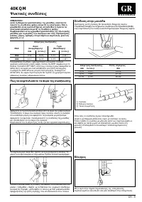
GR - 1 4 0 K Q M TY GLOBAL − IR Remote Control Room Controller Zone Manager H )*+,-. )/*012 +. 34+-1512 )1 .360).7* 4/80450* 91:0:37;0:*, )1 7* *).-:=>91:0:37;0:* Carrier Room Controller ; Zone Manager. : * - A B 2 1 C 1 B = . 7 , 3 7 . 3 A C B : . 7 * 7 A D 1 9 1 : 0 : 3 7 ; 0 : * 4 / 8 0 4 5 0 ...
Page 108 - Comando à distância; Índice
P - 1 4 0 K Q MClimatizador de ar - sistema split unidade interior - “Global Cassette” POR TUGUÊS Comando à distância “Room Controller” “Zone Manager” A unidade pode ser combinada ao comando de raios infravermelhos, ou aocomando à distância via cabo, ligado ao “Room Controller” ou “Zone Manager”.As ...
Page 109 - Dimensões e pesos; Unidade
4 0 K Q M P - 2 Dimensões e pesos 40KQM 012, 015 Unidade 19 Grupo moldura e grelha 3 kg 575 298 120 225 280 56 52 91 575 158 720 550 515 Ø 150 Ø 70 50 30 Ø 25 40KQM012, 015
Page 110 - Tabela IV: Componentes necessários para completar a montagem; Dados técnicos; Tabela I: Características nominais; Tabela III: Limites de funcionamento
4 0 K Q M P - 3 P O RT U G U Ê S Tabela IV: Componentes necessários para completar a montagem Descrição Especificação Tubo de ligação 40KQM012 Ø (3/8”) 9.52mm ( G á s ) / Ø (1/4”) 6.35mm (Líquido) 40KQM015 Ø (1/2”) 12.7mm ( G á s ) / Ø (1/4”) 6.35mm (Líquido) Anel de ligação de paredeCapuz de parede...
Page 111 - Para a instalação; Informação Geral; Escolha do local de instalação
4 0 K Q M P - 4 Para a instalação Leia atentamente este manual antes de iniciar a instalação. • Esta unidade está conforme as Directivas de Baixa Tensão (CEE/73/23) e Compactibilidade Electromagnética(CEE/89/336). • A instalação deverá ser executada por um instalador qualificado. • Cumpra todas as e...
Page 113 - Instalação
4 0 K Q M P - 6 Máximo duas grelhas fechadas (ver Nota 3) Instalação Atenção: evitar ... ligações eléctricas com folgas.Desaper tar os tubos de ligação do refrigerante depois deinstalados: isto pode provocar a perca do refrigerante. ... excessivo número de cur vas nos tubos de ligação (ver oManual d...
Page 114 - Antes da Instalação
P - 7 4 0 K Q M P O RT U G U Ê S Antes da Instalação Antes de retirar a unidade de dentro da embalagem, recomendamosque a coloque o mais perto possível do lugar onde a irá instalar.A grelha e o comando remoto vêm em embalagens separadas afimde se assegurar uma boa protecção dos mesmos. IMPORTANTE:Nã...
Page 116 - Abocardando as extremidades do tubo; Ligações do refrigerante
P - 9 4 0 K Q M P O RT U G U Ê S ATENÇÃO:Durante a instalação da unidade ligar primeiro o sistema derefrigeração e depois o sistema eléctrico, no caso dedesinstalação da unidade desligar primeiro os caboseléctricos e depois o sistema de refrigeração.Consulte o Manual de Instalação da Unidade Exterio...
Page 117 - Ligações eléctricas; CONFIGURAÇÃO DO SISTEMA
4 0 K Q M P - 10 Ligações eléctricas CONFIGURAÇÃO DO SISTEMA • Fazer as ligações eléctricas entre as unidades antes de ligar o sistema à corrente eléctrica.Certifique-se de que a ligação à corrente eléctrica se fazutilizando um interruptor que desliga todos os pólos com umaaber tura de pelo menos 3 ...
Page 118 - Passagem dos cabos
4 0 K Q M P - 11 P O RT U G U Ê S Ligações eléctricas Bomba de calor - 40KQM012, 015 1 2 3 1 2 3 1 10 80 Notas: • Ver Manual de Instalação da Unidade Exterior. Legenda da caixa de terminais,todos os tamanhos Terra 1 Linha de interligação, unidades interior-exterior 2 Neutro, ligação unidade interior...
Page 119 - Grelha de entrada do ar; Renovação do ar e descarga de ar condicionada numa sala contígua
4 0 K Q M P - 12 120 105 49 Ø A 216 B Ø A Ø C • Os orificios laterais permitem a ligação de uma conduta de entrada do ar renovado e outra para distribuição do ar numa salacontígua. • Tirar o isolamento externo anticondensação e retirar os painéis de chapa utilizando um punção. Distribuição de ar num...
Page 120 - Renovação do ar; Teste de funcionamento
P - 13 4 0 K Q M P O RT U G U Ê S No caso de duas linguetas fechadas, a distribuição do ar no ambiente contíguo é 50% superior àdistribuição com uma só linguetafechada (com igualdade de compressão estática).Com umidade relativa interna superior a 70% é admitido somente um fecho. 30 20 10 0 0 100 200...
Page 121 - Seleccionador de endereços e código de erro; Seleccionador de endereços
4 0 K Q M P - 14 Seleccionador de endereços e código de erro Seleccionador de endereços Se estiver a instalar duas unidades interiores na mesma sala equiser pô-las a funcionar de forma independente, é necessáriofornecer um endereço próprio a cada unidade, para que cada umapossa funcionar através do ...
Page 122 - Manual do utilizador; Indicadores luminosos e manual do utilizador
P - 15 4 0 K Q M P O RT U G U Ê S Manual do utilizador Quando tiver terminado a instalação e os testes deve explicar aoUtilizador final os principais pontos do Manual de Instalação eManutenção chamando a atenção para os principais modos defuncionamento da unidade, como se refere a seguir: • Como lig...
Page 123 - SVENSKA; Innehållsförteckning; Sida
S - 1 4 0 K Q MSplit system “Global cassette” inomhusenhet SVENSKA IR Remote Control “Room Controller” “Zone Manager” Detta aggregat kan användas med infraröd fjärrkontroll, med Carriers “RoomController” eller med “Zone Manager” extern styrning.Installeringsanvisningar för fjärrkontrollen med infrar...
Page 124 - Dimensioner och vikter; Aggregat
4 0 K Q M S - 2 Dimensioner och vikter 40KQM 012, 015 Aggregat 19 Ram/galler sammansättning 3 kg 575 298 120 225 280 56 52 91 575 158 720 550 515 Ø 150 Ø 70 50 30 Ø 25 40KQM012, 015
Page 125 - Tekniska data; Tabell I: Nominella data; Tabell III: Driftsgränser
4 0 K Q M S - 3 S V E N S K A Tabell IV: Nödvändiga komponenter för att slutföra installeringen Beskrivning Egenskaper Anslutningsslang 40KQM012 Ø (3/8”) 9.52mm (Gas) / Ø (1/4”) 6.35mm (Vätska)40KQM015 Ø (1/2”) 12.7mm (Gas) / Ø (1/4”) 6.35mm (Vätska) Rörmuff på väggHylsa på väggOmslutningsband Film ...
Page 126 - Aggregatets installation; Allmän information; Val av installationsplats
4 0 K Q M S - 4 Aggregatets installation Läs noggrant igenom denna installationsmanual innaninstallationen påbörjas. • Detta aggregat överensstämmer med direktiven för lågspänning (EEC/73/23) och elektromagnetisk strålning (EEC/89/336). • Installationen skall utföras av en kvalificerad kyltekniker. ...
Page 129 - Innan installation
S - 7 4 0 K Q M S V E N S K A Innan installation Det rekommenderas att placera aggregatet så närainstallationsplatsen som möjligt innan för packningsmaterialetavlägsnas. Grillpanel och fjärrkontroll ligger separat förpackade förmaximalt skydd. VIKTIGT:Lyft ej aggregatet i dräneringsröret eller iköld...
Page 131 - Flare-koppling av rörändar; Köldmedieanslutningar
S - 9 4 0 K Q M S V E N S K A VIKTIGT:Anslut först köldmedieanslutningar och sedan de elektriskaanslutningarna. Vid avinstallation: Koppla först ur de elektriskakablarna och sedan köldmedieanslutningarna. För dimensionering av rör och begränsningar (sluttningar,längd, antal tillåtna böjar, köldmedie...
Page 132 - Elektriska anslutningar; SYSTEMKONFIGURERING
4 0 K Q M S - 10 Elektriska anslutningar SYSTEMKONFIGURERING • Genomför de elektriska anslutningarna mellan aggregaten innan kraftmatningen ansluts. Se till att kraftmatningens anslutning skergenom en brytare som slår ifrån samtliga poler, med ettkontaktgap på minst 3 mm. Kontrollpanelen nås genom a...
Page 133 - Kabelpassage
4 0 K Q M S - 11 S V E N S K A Elektriska anslutningar Värmepump - 40KQM012, 015 1 2 3 1 2 3 1 10 80 Anmärkning: • Se utomhusaggregatets installationsmanual. Förklaring av anslutningsplintar,samtliga modeller Skyddsjord 1 Fasledare mellan inomhus/utomhusaggregat 2 Neutralledare mellan inomhus/utomhu...
Page 134 - Luftinloppsgaller
4 0 K Q M S - 12 120 105 49 Ø A 216 B Ø A Ø C • Körnslagsmarkeringar på sidorna möjliggör anslutning av inloppskanaler för frisk luft samt kanaler för luftdistribution tillangränsande rum. • Avlägsna den yttre kondenseringssäkra isoleringen och ta bor t de förstansade panelerna genom att använda en ...
Page 135 - Uteluftsinblandning; Driftstest
S - 13 4 0 K Q M S V E N S K A I händele av två stängda klaffar är lufttillförseln mot den närliggande lokalen 50% högre jämför t med tillförseln om bara 1 klaff ärstängd (vid likar tad statisk kompression).Med inre relativ fuktighet över 70 % tillåts endast en stängning. 30 20 10 0 0 100 200 300 40...
Page 136 - Val av adress och felkoder; Val av adress
4 0 K Q M S - 14 Val av adress och felkoder Val av adress Om installationen innefattar två inomhusenheter i samma rum ochom man vill att dessa skall arbeta oberoende av varandra, krävsen egen adress till varje enhet så att de kan ha var sin fjärrkontroll.Konfigurationen för detta går till på följand...
Page 137 - Instruktioner för ägaren; Varningslampor och anvisningar för ägaren
S - 15 4 0 K Q M S V E N S K A Instruktioner för ägaren När installation och tester fullbordats, förklara då innehållet i drift-och skötselinstruktionen för ägaren.Ägna speciell uppmärksamhet åt luftkonditioneringens olikadriftslägen, såsom: • Hur man sätter på och stänger av enheten.• Fjärrkontroll...
Page 138 - SUOMI; Sisältö; Sivu
FIN - 1 4 0 K Q MSplit järjestelmän kasettimalliset sisäyksiköt SUOMI IR Remote Control “Room Controller” “Zone Manager” Yksikköä voidaan ohjata etäisohjaimella, Carrierin “Room Controller” tai “ZoneManager”.Infrapuna-kaukosäätimen asennusohjeet löytyvät yksikön käyttö- ja huolto-oppaasta.Muiden ohj...
Page 139 - Mitat ja painot; Yksikkö
4 0 K Q M FIN - 2 Mitat ja painot 40KQM 012, 015 Yksikkö 19 Kehys / Säleikkö 3 kg 575 298 120 225 280 56 52 91 575 158 720 550 515 Ø 150 Ø 70 50 30 Ø 25 40KQM012, 015
Page 140 - Tekniset tiedot; Taulukko I: Nimellistehot; Taulukko III: Toimintarajat
4 0 K Q M FIN - 3 S U O M I Taulukko IV: Täydellisessä asennuksessa tarvittavat komponentit Nimike Tyyppi Kylmäaineputki 40KQM012 Ø (3/8”) 9.52mm (Kaasu) / Ø (1/4”) 6.35mm (Neste)40KQM015 Ø (1/2”) 12.7mm (Kaasu) / Ø (1/4”) 6.35mm (Neste) SeinämuhviSeinäkappaViimeistelynauha PVC-kelmu KiinnitysnauhaS...
Page 141 - Yksikön asennus; Yleiset ohjeet; Asennuspaikan valinta
4 0 K Q M FIN - 4 Yksikön asennus Tämä asennusohje on ehdottomasti luettava ennenasennuksen aloittamista. • Tämä yksikkö noudattaa (EEC/73/23) matalajännite ja (EEC/89/336) sähkömagneetista yhteensopivuusdirektiiviä. • Ongelmattoman asennuksen aikaansaamiseksi asentajan on oltava pätevä ja noudatett...
Page 143 - Asennus
4 0 K Q M FIN - 6 Enintään kaksi tuuletusaukkoa (katso huomausta 3) Varoitukset: vältä …löysiä sähköliitoksia.…irrottamasta jo kerran asennettuja jäähdykeputkiliitoksia, sesaattaa aiheuttaa kylmäainevuotja. … tarpeettomia käännöksiä ja mutkia putkituksessa (katsoulkoyksikön asennusohjetta).Liian pit...
Page 144 - Ennen asennusta
FIN - 7 4 0 K Q M S U O M I Ennen asennusta On suositeltavaa viedä koje niin lähelle asennuspaikkaa kuinmahdollista ennen sen purkamista pakkauksestaan. Säleikkö jaetäisohjain on pakattu erilleen paremman suojauksensaavuttamiseksi. !TÄRKEÄÄ:Älä nosta kojetta kondenssivesiyhteestä taijäähdykeputkiyht...
Page 146 - Putkien päiden syvennys; Jäähdykeputki liitokset
FIN - 9 4 0 K Q M S U O M I TÄRKEÄÄ:Asennuksessa tulee suorittaa ensin kylmäliitännät ja senjälkeen sähköliitännät. Purettaessa tulee ensin kytkeä irtisähkökaapelit ja sen jälkeen kylmäliitännät. Katso ulkoyksikön asennusohjeesta putkikoot ja rajoitukset(kaltevuudet, pituus, mutkien määrä, kylmäaine...
Page 147 - Sähköliitännät; JÄRJESTELMÄN KONFIGUROINTI
4 0 K Q M FIN - 10 Sähköliitännät JÄRJESTELMÄN KONFIGUROINTI • Tee kojeiden väliset johdotukset ensin ja sen jälkeen vasta pääsyöttö.Varmista, että pääsyötössä on kytkin, jolla voi katkaista kaikkinavat, ja joissa kärkien väli on vähintään 3 mm. Ohjauspaneliin päästään irrottamalla kehys sekä metall...
Page 148 - Johdotus
4 0 K Q M FIN - 11 S U O M I Sähköliitännät Lämpöpumppu - 40KQM012, 015 1 2 3 1 2 3 1 10 80 Huomautus: • Katso ulkoyksikön asennusohjetta. Sähkökotelon merkkien selitykset,kaikki mallit Maa 1 Sisäyksikön ja ulkoyksikön välinen vaihejohto 2 Sisäyksikön ja ulkoyksikön välinen nollajohto 3 Yhteys (suur...
Page 149 - Sisäänottosäleikkö
4 0 K Q M FIN - 12 120 105 49 Ø A 216 B Ø A Ø C • Sivuilla olevat taltattavat lähdöt mahdollistavat raittiin ilman sisäänottokanavan liittämisen ja kanavan, jolla johdetaankäsiteltyä ilmaa viereiseen huoneeseen, liitämisen kojeeseen. • Irrota ulkopuolinen esilävistetty eriste sekä irrota lävistimell...
Page 150 - Raittiin ilman sisäänotto; Käyttöönotto
FIN - 13 4 0 K Q M S U O M I Jos kaksi siipeä on kiinni, ilmanvirtaus viereiseen huoneeseen on 50% suurempi kuin 1 siiven ollessa kiinni (samalla staattisellapaineella).Jos suhteellisen sisäkosteus on yli 70 %, vain yksi lukko on sallittu. 30 20 10 0 0 100 200 300 400 24/28 12 18 450 410 60 48 36 40...
Page 151 - Toimintojen valinta ja virhekoodit; Toimintojen valinta
4 0 K Q M FIN - 14 Toimintojen valinta ja virhekoodit Toimintojen valinta Jos olet asentanut kaksi sisäyksikköä samaan huoneeseen jahaluat käyttää niitä yksilöllisesti, on välttämätöntä merkitä kukinyksikkö omalla toiminnallaan jolloin kukin yksikkö voi käyttääomaa kaukosäädintä. Ohjelmointi(konfigu...
Page 152 - Ohjeita käyttäjälle; Yksikön varoitusvalot ja ohjeita käyttäjälle
FIN - 15 4 0 K Q M S U O M I Ohjeita käyttäjälle Kun asennus ja toimintakokeet on tehty selvitä käyttö- ja huolto-ohjeet käyttäjälle kiinnittäen erityisesti huomiota ilmastointikojeenpäätoiminnoille kuten: • Kojeen käynnistys ja pysäytys.• Etäisohjaimen toiminnot.• Ilmansuodattimen irrotus ja puhdis...