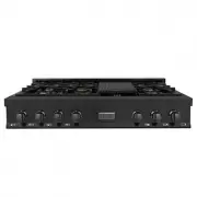
Page 3 - WHAT IS NOT COVERED; WARRANTY; COVERAGE
WARRANTY WHAT IS NOT COVERED 1. Installation or start-up, damages or problems caused by improper installation or use. 2. Improper liquid propane conversion or damage related to improper liquid propane conversion. 3. Cook top burner flame adjustments or related complaints.4. Service by an unauthorize...
Page 5 - and can break under the weight.; IMPORTANT SAFETY INSTRUCTIONS; IMPORTANT SAFETY INSTRUCTIONS; Gener
2 1 WARNING An air curtain or other overhead range/cooktop hood, which operates by blowing downward airflow onto the range, shall not be used/installed in conjunction with this gas range. • The manufacturer will not be responsible for any damage to property or to persons caused by incorrect installa...
Page 6 - BEFORE INSTALLATION; Please keep this manual for future use.; WARRANTY AND SERVICE; arr
4 3 “A” will change with size of range (24”-60”). BEFORE INSTALLATION 2"8/16(63.5) A 32 "1/8 (816) 7"7/8(200) 36"(916) 2"3/4(70) 27"7/16(695) 1"1/4(33) 3/16"(5) 2"3/16(54.5) 21"1/8(537) 2"9/16(65) 32 “ 1 / 8 A 2 “ 1 / 8 “ 3/16 2 “ 9/16 2 “ 3/4 27 “ 7/16 7 ...
Page 7 - sealed before installation of the appliance.; Gas Supply
6 5 ROOM VENTILATION An exhaust fan may be used with the appliance; in each case it shall be installed in conformity with the appropriate national and local standards. Exhaust hood operation may affect other vented appliances; in each case it shall be installed in conformity with the appropriate nat...
Page 8 - INSTALLING THE CHAINS; Installing the Anti-Tip; Installing th; NOTE; INSTALLATION; Installing th
8 7 INSTALLING THE CHAINS The chains shipped with the range must be properly secured to the rear wall. The height of the bracket from the floor must be determined after the range legs have been adjusted to the desired height and after the range has been leveled. If the chain length is too short to p...
Page 9 - Cooking Range; INTERNAL DIMENSIONS; Installation R
10 9 INSTALLATION Installation R equir ements Cooking Range 13” location of gas and electrical extends on floor 36-38” to cooking surface 35” to 40” to bottom of ventilation hood W opening width 18” 6” Front View Side View 2 ³/₄” 3.23” 3.23” 5 ³/₄” 9 ³/₄” 12” gas 5” gas 2” 27 ¹/₂” EXTERNAL DIMENSION...
Page 10 - Electrical Connection; Power R; Four-Wire Connection; ELECTRICAL GROUNDING; ELECTRIC POWER RATING
12 11 Electrical Connection INSTALLATION INSTALLATION Power R ating & Electrical Connection L2 (red) N (white) G (green) L1 (black) L2 (red) N (white) G (green) L1 (black) cable from power supply Four-Wire Connection Receptacle NEMA 14-50R ELECTRICAL GROUNDING Our oven is equipped with a four-pr...
Page 11 - GAS CONNECTION; Gas Connection
14 13 MANUAL SHUT-OFF VALVE • This valve is not shipped with the appliance and must be provided by the installer. • The manual shut-off valve must be installed in the gas service line between the gas hook-up on the wall and the appliance inlet, in position where it can be reached quickly in the even...
Page 12 - Save the nozzles removed from the range for future use.; LPG: Liquid Propane Gas; PRESSURE REGULATOR
16 15 The gas conversion procedure for this range includes: 1. Pressure Regulator2. Surface Burners3. Flame AdjustmentThe conversion is not finished if all steps are not completed. Before performing the gas conversion, locate the package containing the replacement nozzles, which has a number indicat...
Page 13 - Propane
18 17 INSTALLATION Gas Connection Propane Conversion Video SCAN ME SCAN ME Gas Connection The gas conversion procedure for this range includes: 1. Pressure Regulator2. Surface Burners3. Flame AdjustmentThe conversion is not finished if all steps are not completed. Before performing the gas conversio...
Page 14 - STEP 1: PRESSURE REGULATOR; Gas Conversion Procedure; Gas Conver
20 19 STEP 1: PRESSURE REGULATOR The pressure regulator supplied with the appliance is a convertible type pressure regulator for use with Natural Gas at a nominal outlet pressure of 4˝ w.c. or LP gas at a nominal outlet pressure of 11” w.c. and it is pre-assembled from the factory to operate with on...
Page 15 - STEP 3: FLAME ADJUSTMENT; WIRING DIAGRAM; Flame Adjustment
22 21 STEP 2: SURFACE BURNERS 1. To replace the nozzles of the surface burners, lift up the burners and unscrew the nozzles shipped with the range using a 7 mm (socket wrench). 2. Replace nozzles using the conversion set supplied with the range. Each nozzle has a number indicating its flow diameter ...
Page 16 - OPERATION; INSTALLATION CHECKLIST; Room V
24 23 ROOM VENTILATION The use of a gas cooking appliance generates heat and humidity in the room where it is installed. Proper ventilation in the room is needed. Make sure the kitchen is equipped with a range hood of appropriate power (400 CFM minimum). Activate the exhaust fan/range hood when poss...
Page 17 - SURFACE BURNER OPERATION - ELECTRIC IGNITION; Cooktop Cooking
26 25 OPERATION SURFACE BURNER OPERATION - ELECTRIC IGNITION To activate the electric ignition, simply turn the control knob counter-clockwise to maximum power, then press the knob in to start the flow of gas and the ignition spark. The spark will be released at the metal tip of the white ceramic pi...
Page 18 - Oven Functions Selector; Oven Functions Selector; Maximum Flame Height; Using th
28 27 OPERATION OVEN FUNCTION SELECTORS - RA/RAB/RAS MODELS The temperature dial must be set to the preferred temperature and the baking dial must be set to the preferred cooking function. OFF Max 250 300 350 400 450 Symbols: Oven Functions Selector OFF Conv.Broil HighBake Broil LowBake Conv.Bake Sy...
Page 19 - PLACEMENT OF OVEN RACKS CONTINUED; USING PANS CORRECTLY
30 29 OPERATION PLACEMENT OF OVEN RACKS CONTINUED 5. DO NOT TOUCH HEATING ELEMENTS OR INTERIOR SURFACE OF OVEN. Heating elements may be hot even though they are dark in color. Interior surfaces of an oven become hot enough to cause burns. During and after use, do not touch, or let clothing or other ...
Page 20 - MAINTENANCE AND CLEANING; OVEN OPERATION GUIDE; Maintaining th
32 31 MAINTENANCE AND CLEANING REPLACING THE OVEN BULBS To replace the oven light bulb, unscrew the protection cap that projects out inside the oven. NOTE : Touching the bulb with your fingers may cause the bulb to burn out. Always use protective gloves or a clean cloth to remove the bulb. CLEANING ...
Page 21 - TROUBLESHOOTING; oublesh; Troublesh; • Cleaning Porcelain:; Changing; RANGE PROBLEM
34 33 TROUBLESHOOTING Tr oublesh ooting Changing Door s MAINTENANCE AND CLEANING Troublesh ooting Changing Door s Door does not lock during cleaning. Use caution. WARNING • Cleaning Porcelain: Porcelain parts should be cleaned frequently with warm soap and water solution applied with a soft sponge o...
Page 22 - Installation Guide and User Manual
Installation Guide and User Manual 1-614-777-5004 2.6.0 www.zlinekitchen.com