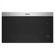
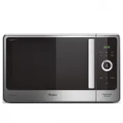
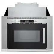
Whirlpool WMMF5930PZ - Manuals
Whirlpool WMMF5930PZ Microwave – User Manual, Manual, Installation Manual in PDF format online.
Manuals:
User Manual Whirlpool WMMF5930PZ


Summary
2 MICROWAVE OVEN SAFETY Your safety and the safety of others are very important. We have provided many important safety messages in this manual and on your appliance. Always read and obey all safety messages. This is the safety alert symbol.This symbol alerts you to potential hazards that can kill o...
3 IMPORTANT SAFETY INSTRUCTIONS � Use care when cleaning the vent-hood filter. Corrosive cleaning agents, such as lye-based oven cleaners, may damage the filter. � To reduce the risk of fire in the oven cavity: • Do not overcook food. Carefully attend appliance when paper, plastic, or other combusti...
4 MICROWAVE OVEN MAINTENANCE AND CARE General Cleaning IMPORTANT: Before cleaning, make sure all controls are off and the microwave oven is cool. Always follow label instructions on cleaning products.Soap, water, and a soft cloth or sponge are suggested first, unless otherwise noted. STAINLESS STEEL...
Manual Whirlpool WMMF5930PZ


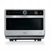
Installation Manual Whirlpool WMMF5930PZ


Summary
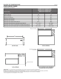
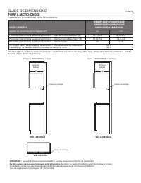
DIMENSION GUIDE 2 of 15 IMPORTANT: Dimensional specifications are provided for planning purposes only. Do not make any cutouts based on this information. Refer to the Installation Guide before selecting cabinetry, verifying electrical/gas connections, making cutouts or beginning installation.All app...
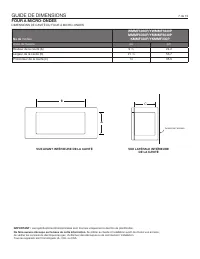
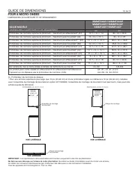
DIMENSION GUIDE 3 of 15 IMPORTANT: Dimensional specifications are provided for planning purposes only. Do not make any cutouts based on this information. Refer to the Installation Guide before selecting cabinetry, verifying electrical/gas connections, making cutouts or beginning installation.All app...
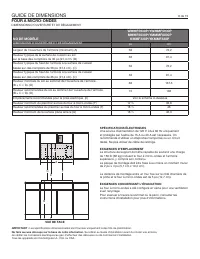
DIMENSION GUIDE 4 of 15 IMPORTANT: Dimensional specifications are provided for planning purposes only. Do not make any cutouts based on this information. Refer to the Installation Guide before selecting cabinetry, verifying electrical/gas connections, making cutouts or beginning installation.All app...
Whirlpool Microwaves Manuals
-
 Whirlpool AMW 433
Manual
Whirlpool AMW 433
Manual
-
 Whirlpool AMW 848
Manual
Whirlpool AMW 848
Manual
-
Whirlpool AVM 390
Manual
-
 Whirlpool JQ280BL
User Manual
Whirlpool JQ280BL
User Manual
-
 Whirlpool JQ280IX
User Manual
Whirlpool JQ280IX
User Manual
-
 Whirlpool JT479IX
User Manual
Whirlpool JT479IX
User Manual
-
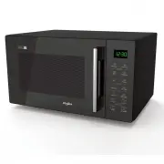
 Whirlpool MWC25BK
User Manual
Whirlpool MWC25BK
User Manual
-
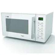
 Whirlpool MWC25WH
User Manual
Whirlpool MWC25WH
User Manual
-
 Whirlpool MWCF25BK
User Manual
Whirlpool MWCF25BK
User Manual
-
 Whirlpool MWF421BL
User Manual
Whirlpool MWF421BL
User Manual
-
 Whirlpool MWF427BL
User Manual
Whirlpool MWF427BL
User Manual
-
 Whirlpool MWP301B
User Manual
Whirlpool MWP301B
User Manual
-
Whirlpool MWP301B
Manual
-
 Whirlpool MWT25BK
User Manual
Whirlpool MWT25BK
User Manual
-
 Whirlpool MWT25WH
User Manual
Whirlpool MWT25WH
User Manual
-
 Whirlpool UMC5225GZ
User Manual
Whirlpool UMC5225GZ
User Manual
-
Whirlpool UMC5225GZ
Installation Manual
-
 Whirlpool UMCS5022PZ
User Manual
Whirlpool UMCS5022PZ
User Manual
-
 Whirlpool UMH50008HS
User Manual
Whirlpool UMH50008HS
User Manual
-
 Whirlpool UMV1160CB
User Manual
Whirlpool UMV1160CB
User Manual