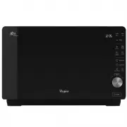
Whirlpool WML75011HW - Manuals
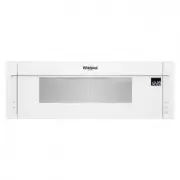
Whirlpool WML75011HW Microwave – User Manual, Installation Manual, Manual in PDF format online.
Manuals:
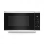
User Manual Whirlpool WML75011HW


Installation Manual Whirlpool WML75011HW


Summary
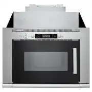
2 INSTALLATION REQUIREMENTS Tools and Parts Tools needed Gather the required tools and parts before starting installation. Read and follow the instructions provided with any tools listed here. ■ Measuring tape ■ Pencil ■ Masking tape or thumbtacks ■ Scissors ■ No. 3 Phillips screwdriver for ¼- 20 x ...
3 Installation Dimensions NOTE: The grounded 3 prong outlet must be inside the upper cabinet. See the “Electrical Requirements” section. *Overall depth of product will vary slightly depending ondoor design. A. 2" x 4" wall studB. Grounded 3 prong outlet 12" (30.5 cm) min.14" (35.6 cm...
4 Wall Venting Installation Only 1. Using diagonal wire cutting pliers, gently snip out the rectangular vent cover on the damper plate. Install Damper Assembly (for wall venting only) 1. Check th at damper blade moves freely, and opens fully. 2. Position the damper assembly on the back of the microw...
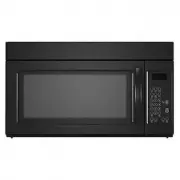
Manual Whirlpool WML75011HW


Summary
Refrigerator Model Serial Model Serial WRB119WFBB ___________________________ WRB119WFBM ___________________________ WRB119WFBW ___________________________ WRS588FIHZ ___________________________ WRS588FIHW ___________________________ WRFA60SMHZ ___________________________ WRF560SEHZ ________________...
WSR57R18DM ___________________________ WRS586FIEM ___________________________ WRS555SIHB ___________________________ WRS555SIHW ___________________________ WRS571CIHB ___________________________ WRS571CIHW ___________________________ WRS970CIHZ ___________________________ WRS973CIHV ________________...
Range Model Serial Model Serial WFE975H0HV ___________________________ WFG975H0HV ___________________________ WEE750H0HZ ___________________________ WEE750H0HV ___________________________ WEG750H0HZ ___________________________ WEG750H0HV ___________________________ WEEA25H0HZ _______________________...
Whirlpool Microwaves Manuals
-
 Whirlpool AMW 433
Manual
Whirlpool AMW 433
Manual
-
 Whirlpool AMW 848
Manual
Whirlpool AMW 848
Manual
-
Whirlpool AVM 390
Manual
-
 Whirlpool JQ280BL
User Manual
Whirlpool JQ280BL
User Manual
-
 Whirlpool JQ280IX
User Manual
Whirlpool JQ280IX
User Manual
-
 Whirlpool JT479IX
User Manual
Whirlpool JT479IX
User Manual
-
 Whirlpool MWC25BK
User Manual
Whirlpool MWC25BK
User Manual
-
 Whirlpool MWC25WH
User Manual
Whirlpool MWC25WH
User Manual
-
 Whirlpool MWCF25BK
User Manual
Whirlpool MWCF25BK
User Manual
-
 Whirlpool MWF421BL
User Manual
Whirlpool MWF421BL
User Manual
-
 Whirlpool MWF427BL
User Manual
Whirlpool MWF427BL
User Manual
-
 Whirlpool MWP301B
User Manual
Whirlpool MWP301B
User Manual
-
Whirlpool MWP301B
Manual
-
 Whirlpool MWT25BK
User Manual
Whirlpool MWT25BK
User Manual
-
 Whirlpool MWT25WH
User Manual
Whirlpool MWT25WH
User Manual
-
 Whirlpool UMC5225GZ
User Manual
Whirlpool UMC5225GZ
User Manual
-
Whirlpool UMC5225GZ
Installation Manual
-
 Whirlpool UMCS5022PZ
User Manual
Whirlpool UMCS5022PZ
User Manual
-
 Whirlpool UMH50008HS
User Manual
Whirlpool UMH50008HS
User Manual
-
 Whirlpool UMV1160CB
User Manual
Whirlpool UMV1160CB
User Manual