Whirlpool WML35011KW - Manuals
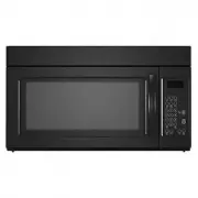
Whirlpool WML35011KW Microwave – User Manual, Manual, Installation Manual in PDF format online.
Manuals:
User Manual Whirlpool WML35011KW


Manual Whirlpool WML35011KW


Summary
2 MICROWAVE HOOD COMBINATION SAFETY You can be killed or seriously injured if you don't immediately You can be killed or seriously injured if you don't follow All safety messages will tell you what the potential hazard is, tell you how to reduce the chance of injury, and tell you what canhappen if t...
3 INSTALLATION REQUIREMENTS Tools and Parts Tools needed Gather the required tools and parts before starting installation. Read and follow the instructions provided with any tools listed here. ■ Measuring tape ■ Pencil ■ Masking tape or thumbtacks ■ Scissors ■ No. 3 Phillips screwdriver for 1/4 - 20...
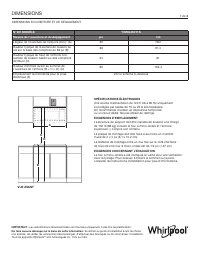
4 Installation Dimensions NOTE: The grounded 3 prong outlet must be inside the upper cabinet. See the “Electrical Requirements” section. *24" (61 cm) is typical for 60" (152.4 cm) installation height exact dimensions may vary depending on type of range/cooktop below. NOTE: To ensure good per...
Installation Manual Whirlpool WML35011KW


Summary
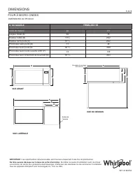
DIMENSIONS IMPORTANT: Dimensional specifications are provided for planning purposes only. Do not make any cutouts based on this information. Refer to the Installation Guide before selecting cabinetry, verifying electrical/gas connections, making cutouts or beginning installation.All Whirlpool ® appl...
DIMENSIONS IMPORTANT: Dimensional specifications are provided for planning purposes only. Do not make any cutouts based on this information. Refer to the Installation Guide before selecting cabinetry, verifying electrical/gas connections, making cutouts or beginning installation.All Whirlpool ® appl...
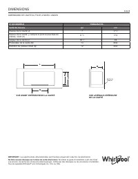
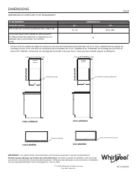
DIMENSIONS 5 de 8 FOUR À MICRO-ONDES IMPORTANT : Les spécifications dimensionnelles sont fournies uniquement à des fins de planification. Ne faire aucune découpe sur la base de cette information. Se référer au guide d’installation avant de choisir une armoire, de vérifier les connexions électriques/...
Whirlpool Microwaves Manuals
-
 Whirlpool AMW 433
Manual
Whirlpool AMW 433
Manual
-
 Whirlpool AMW 848
Manual
Whirlpool AMW 848
Manual
-
Whirlpool AVM 390
Manual
-
 Whirlpool JQ280BL
User Manual
Whirlpool JQ280BL
User Manual
-
 Whirlpool JQ280IX
User Manual
Whirlpool JQ280IX
User Manual
-
 Whirlpool JT479IX
User Manual
Whirlpool JT479IX
User Manual
-
 Whirlpool MWC25BK
User Manual
Whirlpool MWC25BK
User Manual
-
 Whirlpool MWC25WH
User Manual
Whirlpool MWC25WH
User Manual
-
 Whirlpool MWCF25BK
User Manual
Whirlpool MWCF25BK
User Manual
-
 Whirlpool MWF421BL
User Manual
Whirlpool MWF421BL
User Manual
-
 Whirlpool MWF427BL
User Manual
Whirlpool MWF427BL
User Manual
-
 Whirlpool MWP301B
User Manual
Whirlpool MWP301B
User Manual
-
Whirlpool MWP301B
Manual
-
 Whirlpool MWT25BK
User Manual
Whirlpool MWT25BK
User Manual
-
 Whirlpool MWT25WH
User Manual
Whirlpool MWT25WH
User Manual
-
 Whirlpool UMC5225GZ
User Manual
Whirlpool UMC5225GZ
User Manual
-
Whirlpool UMC5225GZ
Installation Manual
-
 Whirlpool UMCS5022PZ
User Manual
Whirlpool UMCS5022PZ
User Manual
-
 Whirlpool UMH50008HS
User Manual
Whirlpool UMH50008HS
User Manual
-
 Whirlpool UMV1160CB
User Manual
Whirlpool UMV1160CB
User Manual