Whirlpool WFE2B19XAUS - Manuals
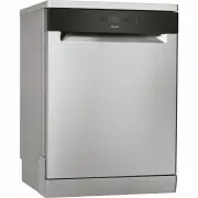
User Manual Whirlpool WFE2B19XAUS


Summary
2 Health and Safety guide ......................................................................................................................... 3 Use and Care guide PRODUCT DESCRIPTION ..................................................................................................................
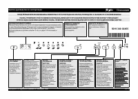
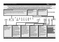
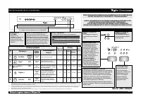
5 EN USE AND CARE GUIDE Before using the appliance carefully read Health and Safety guide. APPLIANCE PRODUCT DESCRIPTION CONTROL PANEL 0000 000 00000 Service: 1 2 3 456 10 12 7 11 9 8 1. Upper rack2. Foldable flaps3. Upper rack height adjuster4. Upper spray arm5. Lower rack6. Cutlery basket7. Lower ...
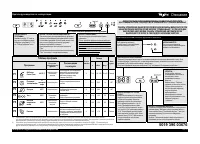
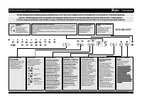
6 ADVICE REGARDING THE FIRST TIME USE After installation, remove the stoppers from the racks and the reta- ining elastic elements from the upper rack. FILLING THE SALT RESERVOIR The use of salt prevents the formation of LIMESCALE on the dishes and on the machine’s functional components. • It is impo...
Whirlpool Dishwashers Manuals
-
 Whirlpool ADG 7200
User Manual
Whirlpool ADG 7200
User Manual
-
 Whirlpool ADG 7443 A+ FD
User Manual
Whirlpool ADG 7443 A+ FD
User Manual
-
 Whirlpool ADG 7643 A+ IX
User Manual
Whirlpool ADG 7643 A+ IX
User Manual
-
 Whirlpool ADG 7653 A+ PC TR FD
User Manual
Whirlpool ADG 7653 A+ PC TR FD
User Manual
-
 Whirlpool ADG 8793 A++ PC TR FD
User Manual
Whirlpool ADG 8793 A++ PC TR FD
User Manual
-
 Whirlpool ADG 9673 A++ FD
User Manual
Whirlpool ADG 9673 A++ FD
User Manual
-
 Whirlpool ADP 321 WH
User Manual
Whirlpool ADP 321 WH
User Manual
-
 Whirlpool ADP 6342 A+ PC WH
User Manual
Whirlpool ADP 6342 A+ PC WH
User Manual
-
 Whirlpool ADP 650
User Manual
Whirlpool ADP 650
User Manual
-
 Whirlpool ADP 7452 A+ PC TR6S IX
User Manual
Whirlpool ADP 7452 A+ PC TR6S IX
User Manual
-
 Whirlpool ADP 7570 IX
User Manual
Whirlpool ADP 7570 IX
User Manual
-
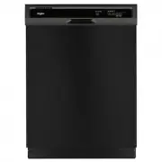
 Whirlpool UDT518SAHP
User Manual
Whirlpool UDT518SAHP
User Manual
-
 Whirlpool UDT555SAHP
User Manual
Whirlpool UDT555SAHP
User Manual
-
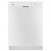
 Whirlpool WDF330PAHB
User Manual
Whirlpool WDF330PAHB
User Manual
-
 Whirlpool WDF330PAHW
User Manual
Whirlpool WDF330PAHW
User Manual
-
 Whirlpool WDF331PAMB
User Manual
Whirlpool WDF331PAMB
User Manual
-
Whirlpool WDF331PAMW
User Manual
-
 Whirlpool WDF332PAMB
User Manual
Whirlpool WDF332PAMB
User Manual
-
Whirlpool WDF332PAMS
User Manual
-
Whirlpool WDF332PAMW
User Manual