Page 2 - WARNING; CONDITIONS OF USE
2 CONTENTS Important Instructions _________________________ 3Part names __________________________________ 4Before first use _______________________________ 6Using your cooktop ___________________________ 7Burners _____________________________________ 7 Cleaning and care ____________________________...
Page 3 - CAUTION; BEFORE USING YOUR APPLIANCE; IMPORTANT; IMPORTANT INSTRUCTIONS
3 CAUTION Read the following carefully to avoid an electric shock or fire. It is important to use your cooktop safely. Check these safety points before using your cooktop.• This appliance is not intended for use by persons (including children) with reduced physical, sensory or mental capabilities, o...
Page 4 - Description of the burner; PART NAMES; Figure 2a
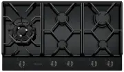
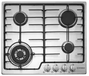
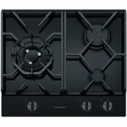
4 Description of the burner PART NAMES Figure 2a WHG639BD 1 Burners – this unit has a small, large and dual wok burner 2 Ceramic Glass hob – the glass hob is resistant to heat, cold and rapid temperature changes, but is vulnerable to impact. A pepper mill falling on the hob could crack it. Never sta...
Page 5 - Figure 2b
5 5 4 1 6 3 2 WHG959BD 1 Burners – this unit has small, medium, large and dual wok burner 2 Ceramic Glass hob – the glass hob is resistant to heat, cold and rapid temperature changes, but is vulnerable to impact. A pepper mill falling on the hob could crack it. Never stand or put heavy loads on the ...
Page 6 - INSTALLATION; MUST provide a Certificate of Compliance; SERVICING; Do not use caustic based cleaners.; BEFORE FIRST USE; CONTROLS
6 INSTALLATION • An authorised person must install this appliance and MUST provide a Certificate of Compliance . This certificate should be retained along with purchase information. • Before using the appliance, ensure that all packing materials are removed from the appliance. • In order to avoid an...
Page 7 - BURNERS
7 Figure 3Standard burner Dual wok burner Both rings of wok burner operate in this range of knob rotation Note that the dotted line section of the graphics is the transition between operating zones. It is recommended not to leave the knob in this position Only the inner ring of the wok burner operat...
Page 8 - CLEANING AND CARE
8 CAUTION Ensure the appliance is off and cool before cleaning. Enamel (on burner skirts and trivets) Persistent stains may require rubbing with a nylon scourer or creamed powder cleansers. Household enamel cleaners are available, follow the manufacturer’s instructions in their use. Harsh abrasive c...
Page 9 - Ceramic Cooktop Cleaning
9 Ceramic Cooktop Cleaning CUSTOMER ADVICE Sometimes SURFACE stains appear to be a “bubble” mark under the ceramic glass. These can be cleaned off with a razor blade scraper and ceramic cleaner. Keeping the ceramic cooktop clean and protected will keep it in good condition and help avoid breakage. C...
Page 10 - TROUBLE SHOOTING
10 TROUBLE SHOOTING FAULT POSSIBLE CAUSES REMEDY Burner will not light even though the sparker is working. • Knob not held down long enough in ‘High’ or ‘Max’ position for flame safeguard to engage • Repeat lighting procedure and hold knob down for 5 seconds in ‘High’ or ‘Max’ position (refer page 7...
Page 11 - INSTALLATION INSTRUCTIONS
11 This appliance must be installed by an authorised person and in compliance with:1. AS/NZS 5601.1 Gas Installations Part 1: General Installations, and AS/NZS 5601.2 Gas Installations Part 2: LP Gas installations in caravans and boats for non-propulsive purposes, or the relevant installation code f...
Page 12 - Figure 5c – Clearance from bench to bottom
12 Figure 5b – WHG959BD * to combustible surface (dimension is not relevant if the adjacent surface is non-combustible). Model Non-Combustible surface(mm) Combustible surface(mm) WHG639BD 55 75 WHG959BD 55 75 Figure 5c – Clearance from bench to bottom Clearanc e 4 9 0 1 4 6 m i n * gas supply connec...
Page 13 - TECHNICAL DATA; features
13 TECHNICAL DATA We reserve the right to alter these specifications. This appliance conforms to AS 5263.Table 2 features WHG639BD WHG959BD Cooking zones 3 5 Wok Yes, dual Yes, dual Ignition 230-240V 230-240V Trivet Cast Cast Hob material Ceramic glass Ceramic glass Features Ignition through knob Ig...
Page 14 - INSTALLAT I ON PROCEDURE
14 1 . 2. 3 . 4 . 5 . 6 . INSTALLAT I ON PROCEDURE WARNING! The bench cutout should be made as per cutout dimensions in Table 2 and Figure 5. Adjacent walls, cupboards and protection for combustible materials: Ensure that the appliance is installed in accordance with AS/NZS 5601.1, or AS/NZS 5601.2 ...
Page 15 - INSTALLATION PROCEDURE
15 INSTALLATION PROCEDURE (CONTINUED) Figure 6a – WHG639BD Figure 6b – WHG959BD combustible surface combustible surface 115 115 124 114 120 101 NOTE: Distances shown to adjacent walls/surfaces are for the distance to a combustible surface. If the surface is not combustible the measurement can be sma...
Page 17 - Supply pipe sizing; ELBOW POSITIONING; Regulator; GAS CONNECTION
17 OPERATION ON N.G./S.N.G This appliance is supplied for use with Natural Gas. However, it can be converted for use with LPG. Refer to LP conversion on page 19. Supply pipe sizing The total hourly gas consumption for the appliance is shown on the data label. The required supply pressure (i.e. at in...
Page 18 - CHECKING THE GAS SUPPLY; Table 3; Assembly of the regulator
18 CHECKING THE GAS SUPPLY 1. Check the manometer zero point is correct. 2. Connect the manometer to the cooktop pressure point. This is located on the regulator. 3. Turn on the gas supply and electricity and try to ignite the gas. NOTE! It will take additional time to light the gas for the first ti...
Page 19 - LPG CONVERSION
19 LPG CONVERSION This appliance is supplied set up for Natural Gas usage. A conversion kit is included with the product for Universal LPG usage. The conversion kit contains the appropriate injectors and 1 LPG sticker.Please follow the procedure below if a conversion to suit UNIVERSAL LPG is require...
Page 20 - Diagram 1; WEIGHT
20 Diagram 1 D ANGER 22 0- 240 VO LT S AC D IS C O NNE C T F R OM S U P P LY B E FO R E RE M O V IN G PA N E L 220-240V IGNITION BOX BODY E N L KNOB IGNITION SWITCHES TO BURNER SPARK PLUGS The appliance is supplied with a standard 7.5 Amp service cord terminated by a 3-pin plug for connection to a s...
Page 21 - TESTING APPLIANCE OPERATION; Figure 9
21 After installation, test the appliance and ensure that it operates correctly before handing it over to the customer. The following procedure is recommended:1. Turn on the gas and electricity supply and attempt ignition on all burners, both separately and in combination. (For correct procedure ref...
Page 22 - NOTES
Page 23 - Warranty
35 WARRANTY This document sets out the terms and conditions of the product warranties for Westinghouse Appliances. It is an important document. Please keep it with your proof of purchase documents in a safe place for future reference should there be a manufacturing defect in your Appliance. This war...