Page 3 - GENERAL SAFETY RULES
WARNING: Dust generated from certain materials can be hazardous to your health. Always operate the tool in a well-ventilated area and wear dust mask. Use dust collection systems when processing wood and plastics. Dust extractors or dust bags must not be connected when processing metals. PERSONAL SAF...
Page 4 - WORKPIECE SAFETY
POWER TOOL USE AND CARE 1. Avoid accidental start-ups. Make sure the power switch is in the OFF position before connecting the plug to a power source or carrying the tool. 2. Check power tool for damaged parts. Check for misalignment of moving parts, jamming, breakage, improper mounting, or any othe...
Page 5 - OPERATION SAFETY; Do not put fingers or any objects into the chip extraction port.; MAINTENANCE SAFETY; SPECIFIC RULES FOR THE PLANER
OPERATION SAFETY 1. Always use ANSI Z87.1 approved safety glasses. Wear hearing protection to prevent hearing damage during op-eration. Use face mask or dust mask if cutting operation is dusty. 2. Keep handles and hands dry, clean and free from oil and grease. Slippery surfaces can cause you to lose...
Page 6 - AMPERAGE; ELECTRICAL INFORMATION; GROUNDING INSTRUCTIONS; REPAIR OR REPLACE a damaged or worn cord immediately.
WARNING : This tool is for indoor use only. Do not expose to rain or use in damp locations. GUIDELINES AND RECOMMENDATIONS FOR EXTENSION CORDS When using an extension cord, be sure to use one heavy enough to carry the current your product will draw. An undersized cord will cause a drop in line volta...
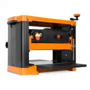
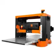
Page 7 - KNOW YOUR PLANER
KNOW YOUR PLANER Adjustable Front Shoe Depth Adjustment Knob Depth Adjustment Gauge Chip Extraction Port Drive Belt Cover Fixed Rear Shoe Handle Trigger Lock Chip Extraction Guide Switch Parallel Guide Fence Blade Wrench Dust Port ON/OFF Switch Carefully unpack the hand planer from the box. Check al...
Page 8 - Shavings may jam in the dust extraction; SWITCHING ON AND OFF; OPERATION
USING THE SAFETY KICKSTAND The safety kickstand (Fig. B - 1) on the bottom of the planer can be engaged to help keep the blade from coming into contact with the work surface when the planer is not in use. To engage the safety kickstand during time of rest, slide the stand until it springs out. To di...
Page 9 - Direction of Grain; DETERMINING THE FEED RATE
THE DO’S AND DONT’S OF GRAIN DIRECTION It is important that the planer should always be cutting in the same direction as the grain of the wood (Fig. F). There are six sides to ev-ery board: two face grains, two side/edge grains, and two end grains. You can plane along the direction of the grain with...
Page 10 - OPERATING YOUR PLANER; Secure the workpiece to a stable platform.; CAUTION; Make sure that the workpiece is secured to a stable platform.
WARNING: Wear safety goggles at all times that comply with ANSI Z87.1. Use ear protection such as plugs or muffs during extended periods of operation. Wear work gloves to protect your hands. Wear a face mask or dust mask to fight the dust. OPERATION OPERATING YOUR PLANER 1. Secure the workpiece to a...
Page 11 - Rabbeting; USING THE PARALLEL GUIDE FENCE; Disconnect the planer from the power source.; MAKING A RABBETING CUT
11 Fig. I Fig. J Fig. K 1 1 WARNING: To avoid injury from accidental startups, always ensure that the tool is switched OFF and unplugged from the power supply before making any adjustments to the planer. Cutting Width Rabbeting Depth OPERATION 11 USING THE PARALLEL GUIDE FENCE The parallel guide fen...
Page 12 - REMOVING OR INSTALLING PLANER BLADES; ADJUSTMENTS
12 6. Each planer blade has two cutting edges and may be reversed when one of the cutting edges becomes dull or chipped. • If one edge is dull, reverse the blade. • If both edges are dull, remove the old blade and replace it with a new one. WARNING: To avoid injury from accidental startups, always e...
Page 13 - The flat side of the blade should be facing the front of
13 Fig. N WARNING: To avoid injury from accidental startups, always ensure that the tool is switched OFF and unplugged from the power supply before making adjustments or installing or removing blades. Fig. O ADJUSTMENTS should be set to the same cutting level and alignment, otherwise the planed surf...
Page 14 - CARBON BRUSHES; Replace the motor cover and secure with screws.; TOOL LUBRICATION; MAINTENANCE
Fig. P CARBON BRUSHES To maintain maximum efficiency of the motor, we recommend changing the carbon brushes every 60 hours of operation. Re-placement carbon brushes (Model 6534-047) are available at wenproducts.com. Only genuine WEN replacement brushes de-signed specifically for your tool should be ...
Page 15 - LIMITED TWO YEAR WARRANTY
15 WEN Products is committed to building tools that are dependable for years. Our warranties are consistent with this commitment and our dedication to quality. LIMITED WARRANTY OF WEN CONSUMER POWER TOOLS PRODUCTS FOR HOME USE GREAT LAKES TECHNOLOGIES, LLC (“Seller”) warrants to the original purchas...
Page 16 - EXPLODED VIEW AND PARTS LIST
Page 17 - Description
EXPLODED VIEW AND PARTS LIST 17 No. Part No. Description Qty. 1 6534-001 Screw 27 2 6534-002 Belt Cover 1 3 6534-003 Bearing Cover 1 4 6534-004 Screw 4 5 6534-005 Stator 1 6 6534-006 Air Deflection 1 7 6530-036 Washer 4 2 8 6534-008 Screw 2 9 6534-009 Left Handle 1 10 6534-010 Dust Extraction Panel ...