Page 3 - About this Installation Guide; Chapter 1 Introduction; This chapter describes the external components of the switch.; Chapter 2 Installation; This chapter illustrates how to install the switch.; Chapter 3 Connection; This chapter illustrates how to configure the switch.; Audience; switch may differ in appearance from that depicted.; Related Document
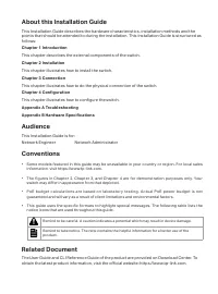
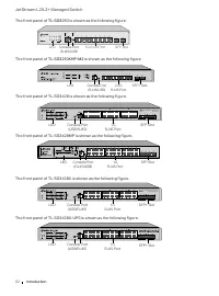
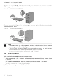
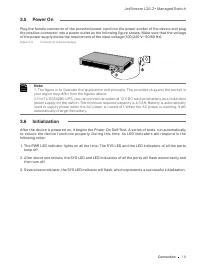
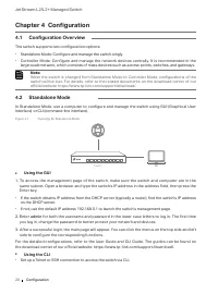
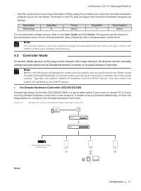
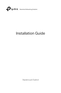
About this Installation Guide This Installation Guide describes the hardware characteristics, installation methods and the points that should be attended to during the installation. This Installation Guide is structured as follows: Chapter 1 Introduction This chapter describes the external component...
Page 4 - Contents; Chapter 1; Configuration Overview; Appendix A Troubleshooting ———————— 23
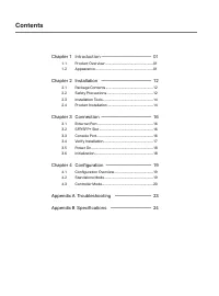
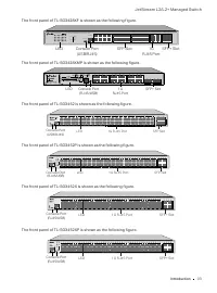
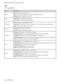
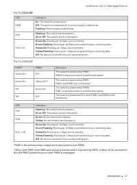
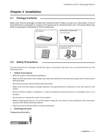
Contents Chapter 1 Introduction ——————————— 01 1.1 Product Overview ...........................................................01 1.2 Appearance .......................................................................01 Chapter 2 Installation ——————————— 12 2.1 Package Contents .........................
Page 5 - Introduction; Chapter 1 Introduction; Product Overview; multiple powerful functions with high security.; Front Panel; LED; LED
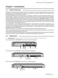
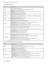
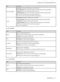
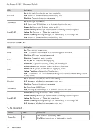
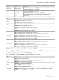
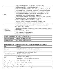
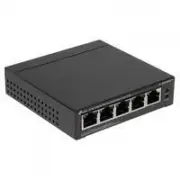
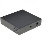
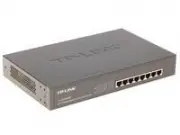
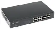
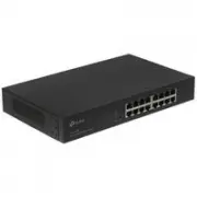
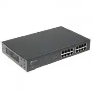
JetStream L2/L2+ Managed Switch 01 Introduction Chapter 1 Introduction 1.1 Product Overview Designed for workgroups and departments, TP-Link JetStream L2/L2+ Managed Switch provides wire- speed performance and abundant L2 management features. It provides a variety of service features and multiple po...
Page 8 - LEDs; : The remaining PoE power keeps ≤ 7 W after this LED is on for 2 minutes.
JetStream L2/L2+ Managed Switch 04 Introduction LEDs For TL-SX3206HPP LED Indication PWR On : The switch is powered on. Off : The switch is powered off or power supply is abnormal. Flashing : Power supply is abnormal. SYS Flashing : The switch works properly. On or Off : The switch works improperly....
Page 14 - Console Port; For PoE switches, the port can also provide power for PDs.
JetStream L2/L2+ Managed Switch 10 Introduction LED Indication FAN Green : All the fans work properly. Yellow : Not all the fans work properly. Speed or PoE (When the Speed LED is on) Green On : Running at 1000 Mbps, but no activity. Green Flashing : Running at 1000 Mbps and transmitting or receivin...
Page 15 - switches, the port can also provide power for PDs.; Port Feature; with a speed of 10 Mbps.; Rear Panel; The rear panel of
JetStream L2/L2+ Managed Switch 11 Introduction switches, the port can also provide power for PDs. SFP/SFP+ Slot SFP slot is designed to install the 1 Gbps SFP module. SFP+ slot is designed to install the 10 Gbps SFP+ module. Port Feature Model 100M/1G/2.5G/ 5G/10Gbps RJ45 Port 100M/1000M/2.5Gbps RJ...
Page 16 - power is working, it will automatically charge the battery.; Kensington Security Slot; the product Support web page, refer to the; Please use the provided power cord.
JetStream L2/L2+ Managed Switch 12 Introduction Note: 1. You can connect an external 12 V DC lead-acid battery as a redundant power supply for the switch. The minimum required capacity is 4.5 AH. 2. Battery is automatically used to supply power when the AC power is turned off. When the AC power is w...
Page 17 - Installation; Chapter 2 Installation; Package Contents; differ in appearance and quantity from the depicted.; Safety Precautions; Keep the power off during the installation.; Site Requirements
JetStream L2/L2+ Managed Switch 13 Installation Chapter 2 Installation 2.1 Package Contents Make sure that the package contains the following items. Please contact your distributor, if any of the listed items is damaged or missing. The figures are for demonstration only. The actual items may differ ...
Page 18 - Clearness
JetStream L2/L2+ Managed Switch 14 Installation Keep the equipment room at an appropriate level of temperature and humidity. Too much or too little humidit y may lead to bad insulation, leakage of electricit y, mechanical proper t y changes, and corrosion. High temperatures may accelerate aging of t...
Page 19 - from the Related Documents:; Installation Tools; Desktop Installation
JetStream L2/L2+ Managed Switch 15 Installation ■ Keep a reasonable cabling system and avoid induced lightning. ■ Use the signal SPD (Surge Protective Device) when wiring outdoor. Note: For detailed lightning protection measures, go to https://www.tp-link.com/support, search the model number of your...
Page 21 - Connection; Chapter 3 Connection
JetStream L2/L2+ Managed Switch 17 Connection Chapter 3 Connection 3.1 Ethernet Port Connect an Ethernet port of the switch to the computer by RJ45 cable as the following figure shows. Figure 3-1 Connecting the RJ45 Port RJ45 Port RJ45 Cable 3.2 SFP/SFP+ Slot The following figure demonstrates the co...
Page 22 - Verify Installation
JetStream L2/L2+ Managed Switch 18 Connection Connect the console (RJ45) port of the device with your computer by the console cable as the following figure shows. Figure 3-3 Connecting the Console (RJ45) Port Connect the console (USB) port of the device with your computer by the USB cable (not provi...
Page 23 - your region may differ from the figures above.
JetStream L2/L2+ Managed Switch 19 Connection 3.5 Power On Plug the female connector of the provided power cord into the power socket of the device and plug the positive connector into a power outlet as the following figure shows. Make sure that the voltage of the power supply meets the requirement ...
Page 24 - Configuration; Chapter 4 Configuration; The switch supports two configuration options:; Using the GUI; er; Using the CLI; Set up a Telnet or SSH connection to access the switch via CLI.
JetStream L2/L2+ Managed Switch 20 Configuration Chapter 4 Configuration 4.1 Configuration Overview The switch supports two configuration options: ■ Standalone Mode: Configure and manage the switch singly. ■ Controller Mode: Configure and manage the network devices centrally. It is recommended in th...
Page 25 - For the detailed configurations, refer to the
JetStream L2/L2+ Managed Switch 21 Configuration ■ Use the console port to access the switch. When using the console port, start the terminal emulation program (such as the Hyper Terminal) on the PC and configure the terminal emulation program as follows: Baud Rate Data Bits Parity Stop Bits Flow Co...
Page 26 - Via Omada Software Controller; . Then run the file and follow the
JetStream L2/L2+ Managed Switch 22 Configuration • Before you start, be sure to power up and connect your devices according to the topology figure. • A DHCP server (typically a router with DHCP function enabled) is required to assign IP addresses to the EAPs and clients in your local network. • Omad...
Page 27 - Launch a Browser to Manage the Network; Cloud Access; Launch; User Guide
JetStream L2/L2+ Managed Switch 23 Configuration Note: To manage your devices, Omada Software Controller needs to keep running on your computer. 1. Launch the Omada Software Controller on your PC. After the initiation process, the controller automatically opens its web page. If not, click Launch a B...
Page 28 - Appendix A Troubleshooting; What could I do if I forgot the username and password of the switch?; both; Why does the PWR/Power LED work abnormally?; LED worked abnormally, take the following steps:; What should I do if I cannot access the web management page?
JetStream L2/L2+ Managed Switch 24 Appendix A Troubleshooting Appendix A Troubleshooting Q1. What could I do if I forgot the username and password of the switch? 1. Connect the console por t of the PC to the console por t of the switch and open a terminal emulation program. 2. Power off and restart ...
Page 29 - Appendix B Specifications; Specifications for Switches with RJ45 Ports and SFP/SFP+ Slots; Item
25 Appendix B Specifications Specifications for Switches with RJ45 Ports and SFP/SFP+ Slots Item Content Standards IEEE 802.3, IEEE 802.3u, IEEE 802.3ab, IEEE 802.3ad, IEEE 802.3z, IEEE 802.3x, IEEE 802.1p, IEEE 802.1q, IEEE 802.1x, IEEE 802.1d, IEEE 802.1s, IEEE 802.1w, IEEE 802.1abIEEE 802.3af/at ...
Page 31 - CE Mark Warning; which case the user may be required to take adequate measures.; EU Declaration of Conformity; Keep the device away from water, fire, humidity or hot environments.
CE Mark Warning This is a class A product. In a domestic environment, this product may cause radio interference, in which case the user may be required to take adequate measures. EU Declaration of Conformity TP-Link hereby declares that the device is in compliance with the essential requirements and...