Page 2 - COPYRIGHT & TRADEMARKS; Specifications are subject to change without notice.; FCC STATEMENT; ) This device may not cause harmful interference.; CE Mark Warning
COPYRIGHT & TRADEMARKS Specifications are subject to change without notice. is a registered trademark of TP-LINK TECHNOLOGIES CO., LTD. Other brands and product names are trademarks or registered trademarks of their respective holders. No part of the specifications may be reproduced in any form ...
Page 3 - Safety Information
Safety Information When product has power button, the power button is one of the way to shut off the product; When there is no power button, the only way to completely shut off power is to disconnect the product or the power adapter from the power source. Don’t disassemble the product, or make r...
Page 4 - CONTENTS; Chapter 1
CONTENTS Package Contents .......................................................................................................................... 1 Chapter 1 About this Guide........................................................................................................... 2 1.1 Intended ...
Page 7 - VI
9.3.1 Global Config ................................................................................................. 125 9.3.2 Port Config ..................................................................................................... 125 9.3.3 OUI Config ........................................
Page 8 - VII
11.4.1 Global Config ................................................................................................. 166 11.4.2 Port Config ..................................................................................................... 168 11.4.3 Radius Server ..................................
Page 9 - VIII
VIII 14.2.3 Remote Log ................................................................................................... 206 14.2.4 Backup Log .................................................................................................... 207 14.3 Device Diagnose.................................
Page 10 - Package Contents
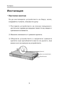
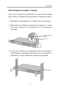
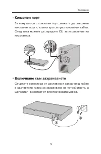
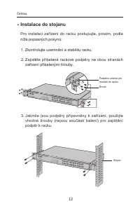
Package Contents The following items should be found in your box: One JetStream L2 Managed Switch One power cord One console cable Two mounting brackets and other fittings Installation Guide Resource CD for TL-SG3210/TL-SG3216/TL-SG3424 switch, including: This User Guide Other Helpfu...
Page 11 - Chapter 1 About this Guide; Intended Readers
Chapter 1 About this Guide This User Guide contains information for setup and management of TL-SG3210/TL-SG3216/ TL-SG3424 JetStream L2 Managed Switch. Please read this guide carefully before operation. 1.1 Intended Readers This Guide is intended for network managers familiar with IT concepts and ne...
Page 14 - Return to CONTENTS
Chapter Introduction Chapter 14 Maintenance This module is used to assemble the commonly used system tools to manage the switch. Here mainly introduces: System Monitor: Monitor the memory and CPU of the switch. Log: View configuration parameters on the switch. Device Diagnose: Test the connect...
Page 15 - Chapter 2 Introduction; Overview of the Switch; Resiliency and Availability; + Supports 4K active VLAN groups and 4K VLAN IDs.; Quality of Service; + Supports L2/L3 granular CoS with 4 priority queues per port.; Security
Chapter 2 Introduction Thanks for choosing the TL-SG3210/TL-SG3216/TL-SG3424 JetStream L2 Managed Switch! 2.1 Overview of the Switch Designed for workgroups and departments, TL-SG3210/TL-SG3216/TL-SG3424 from TP-LINK provides wire-speed performance and full set of layer 2 management features. It pro...
Page 16 - Appearance Description
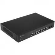
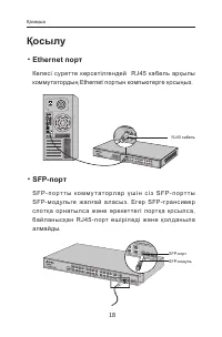
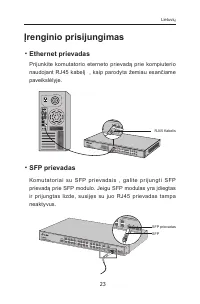
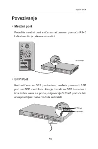
2.3 Appearance Description 2.3.1 Front Panel Figure 2-1 Front Panel The following parts are located on the front panel of the switch: 10/100/1000Mbps Ports: Designed to connect to the device with a bandwidth of 10Mbps, 100Mbps or 1000Mbps. Each has a corresponding 1000Mbps LED. SFP Ports: Design...
Page 18 - Chapter 3 Login to the Switch; for the User; Login; button or press the; Enter
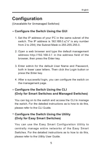
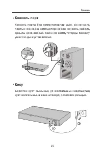
Chapter 3 Login to the Switch 3.1 Login 1) To access the configuration utility, open a web-browser and type in the default address http://192.168.0.1 in the address field of the browser, then press the Enter key. Figure 3-1 Web-browser Tips: To log in to the switch, the IP address of your PC should ...
Page 19 - Clicking; Apply; . You are suggested to click; Saving Config; before cutting off the power or rebooting the
Figure 3-3 Main Setup-Menu Note: Clicking Apply can only make the new configurations effective before the switch is rebooted. If you want to keep the configurations effective even the switch is rebooted, please click Saving Config . You are suggested to click Saving Config before cutting off the pow...
Page 20 - Chapter 4 System
Chapter 4 System The System module is mainly for system configuration of the switch, including four submenus: System Info , User Manage, System Tools and Access Security . 4.1 System Info The System Info, mainly for basic properties configuration, can be implemented on System Summary , Device Descri...
Page 21 - Port Info
Indicates the SFP port is not connected to a device. Indicates the SFP port is at the speed of 1000Mbps. Indicates the SFP port is at the speed of 100Mbps. When the cursor moves on the port, the detailed information of the port will be displayed. Figure 4-2 Port Information Port Info Port: Display...
Page 22 - The following entries are displayed on this screen:
Bandwidth Utilization Rx: Select Rx to display the bandwidth utilization of receiving packets on this port. Tx: Select Tx to display the bandwidth utilization of sending packets on this port. 4.1.2 Device Description On this page you can configure the description of the switch, including device na...
Page 23 - Figure 4-5 System Time; Time Info; Displays the current date and time of the switch.; Time Config; Update Rate: Specify the rate fetching time from NTP server.
Figure 4-5 System Time The following entries are displayed on this screen: Time Info Current System Date: Displays the current date and time of the switch. Current Time Source: Displays the current time Source of the switch. Time Config Manual: When this option is selected, you can set the date ...
Page 24 - DST Config
4.1.4 Daylight Saving Time Here you can configure the Daylight Saving Time of the switch. Choose the menu System → System Info → Daylight Saving Time to load the following page. Figure 4-6 Daylight Saving Time The following entries are displayed on this screen: DST Config DST Status: Enable or dis...
Page 25 - Choose the menu; System; to load the following page.; IP Config; Displays MAC Address of the switch.
Date Mode: Specify the DST configuration in Date mode. This configuration is one-off in use. Offset: Specify the time adding in minutes when Daylight Saving Time comes. Start/End Time: Select starting time and ending time of Daylight Saving Time. Note: 1. When disable the DST, the predefined mod...
Page 27 - User Info
Figure 4-9 User Config The following entries are displayed on this screen: User Info User Name: Create a name for users’ login. Access Level: Select the access level to login. Admin: Admin can edit, modify and view all the settings of different functions. Guest: Guest only can view the setting...
Page 29 - Config Backup
Figure 4-11 Config Backup The following entries are displayed on this screen: Config Backup Backup Config: Click the Backup Config button to save the current configuration as a file to your computer. You are suggested to take this measure before upgrading. Note: It will take a few minutes to backu...
Page 30 - Access Security
4. After upgrading, the device will reboot automatically. 5. You are suggested to backup the configuration before upgrading. 4.3.4 System Reboot On this page you can reboot the switch and return to the login page. Please save the current configuration before rebooting to avoid losing the configurati...
Page 31 - Figure 4-15 Access Control; Access Control Config; Port-based: Select this option to limit the ports for login.
Figure 4-15 Access Control The following entries are displayed on this screen: Access Control Config Control Mode: Select the control mode for users to log on to the Web management page. IP-based: Select this option to limit the IP-range of the users for login. MAC-based: Select this option to...
Page 33 - Figure 4-16 SSL Config; Global Config; Select Enable/Disable the SSL function on the switch.; Certificate Download; connection will not work.
Figure 4-16 SSL Config The following entries are displayed on this screen: Global Config SSL: Select Enable/Disable the SSL function on the switch. Certificate Download Certificate File: Select the desired certificate to download to the switch. The certificate must be BASE64 encoded. Key Downl...
Page 34 - Select Enable/Disable SSH V1 to be the supported protocol.
an insecure network environment. It can encrypt all the transmission data and prevent the information in a remote management being leaked. Comprising server and client, SSH has two versions, V1 and V2 which are not compatible with each other. In the communication, SSH server and client can auto-nego...
Page 35 - Application Example 1 for SSH:
Key Download Key Type: Select the type of SSH Key to download. The switch supports three types: SSH-1 RSA, SSH-2 RSA and SSH-2 DSA. Key File: Select the desired key file to download. Download: Click the Download button to download the desired key file to the switch. Note: 1. Please ensure the key ...
Page 36 - Application Example 2 for SSH:; Network Requirements; PuTTY client software is recommended.; Configuration Procedure; Select the key type and key length, and generate SSH key.
Application Example 2 for SSH: Network Requirements 1. Log on to the switch via password authentication using SSH and the SSH function is enabled on the switch. 2. PuTTY client software is recommended. Configuration Procedure 1. Select the key type and key length, and generate SSH key. Note: 1. ...
Page 39 - Chapter 5 Switching; The following entries are displayed on this screen.
Chapter 5 Switching Switching module is used to configure the basic functions of the switch, including four submenus: Port , LAG , Traffic Monitor and MAC Address . 5.1 Port The Port function, allowing you to configure the basic features for the port, is implemented on the Port Config , Port Mirror ...
Page 41 - Mirror Group List
Figure 5-2 Mirroring Port The following entries are displayed on this screen. Mirror Group List Group: Displays the mirror group number. Mirroring: Displays the mirroring port number. Mode: Displays the mirror mode, the value will be "Ingress" or "Egress". Mirrored Port: Displays t...
Page 42 - Mirror Group
Figure 5-3 Mirroring Port The following entries are displayed on this screen. Mirror Group Number: Select the mirror group number you want to configure. Mirroring Port Mirroring Port: Select the mirroring port number. Mirrored Port Port Select: Click the Select button to quick-select the corre...
Page 43 - Switching
Egress: Select Enable/Disable the Egress feature. When the Egress is enabled, the outgoing packets sent by the mirrored port will be copied to the mirroring port. LAG: Displays the LAG number which the port belongs to. The LAG member can not be selected as the mirrored port or mirroring port. Note: ...
Page 44 - Port Security
Figure 5-4 Port Security The following entries are displayed on this screen: Port Security Select: Select the desired port for Port Security configuration. It is multi-optional. Port: Displays the port number. Max Learned MAC: Specify the maximum number of MAC addresses that can be learned on the ...
Page 45 - Port Isolation Config
Note: 1. The Port Security function is disabled for the LAG port member. Only the port is removed from the LAG, will the Port Security function be available for the port. 2. The Port Security function is disabled when the 802.1X function is enabled. 5.1.4 Port Isolation Port Isolation provides a met...
Page 46 - Port Isolation List; Display the port number.; ” to load the following page.
Port Isolation List Port: Display the port number. Forward Portlist: Display the Forward Portlist. 5.1.5 Loopback Detection With loopback detection feature enabled, the switch can detect loops using loopback detection packets. When a loop is detected, the switch will display an alert or further bl...
Page 48 - Aggregate Arithmetic:
If the ports, which are enabled for the GVRP , 802.1Q VLAN , Voice VLAN , STP , QoS , DHCP Snooping and Port Configuration ( Speed and Duplex , Flow Control ), are in a LAG, their configurations should be the same. The ports, which are enabled for the Port Security , Port Mirror , MAC Address Fi...
Page 50 - Figure 5-8 Static LAG Config; LAG Config; Select a Group Number for the LAG.; LAG Table; The LAG can be deleted by clearing its all member ports.
Figure 5-8 Static LAG Config The following entries are displayed on this screen: LAG Config Group Number: Select a Group Number for the LAG. Description: Give a description to the LAG for identification. LAG Table Member Port: Select the port as the LAG member. Clearing all the ports ofthe LAG w...
Page 52 - Traffic Monitor
Select: Select the desired port for LACP configuration. It is multi-optional. Port: Displays the port number. Admin Key: Specify an Admin Key for the port. The member ports in a dynamic aggregation group must have the same Admin Key. Port Priority: Specify a Port Priority for the port. This value de...
Page 54 - Auto Refresh
Figure 5-11 Traffic Statistics The following entries are displayed on this screen: Auto Refresh Auto Refresh: Allows you to Enable/Disable refreshing the Traffic Summary automatically. Refresh Rate: Enter a value in seconds to specify the refresh interval. Statistics Port: Enter a port number an...
Page 56 - Search Option
Figure 5-12 Address Table The following entries are displayed on this screen: Search Option MAC Address: Enter the MAC address of your desired entry. VLAN ID: Enter the VLAN ID of your desired entry. Port: Select the corresponding port number of your desired entry. Type: Select the type of your de...
Page 59 - Aging Config
Figure 5-14 Dynamic Address The following entries are displayed on this screen: Aging Config Auto Aging: Allows you to Enable/Disable the Auto Aging feature. Aging Time: Enter the Aging Time for the dynamic address. Search Option Search Option: Select a Search Option from the pull-down list and ...
Page 61 - Create Filtering Address
Figure 5-15 Filtering Address The following entries are displayed on this screen: Create Filtering Address MAC Address: Enter the MAC Address to be filtered. VLAN ID: Enter the corresponding VLAN ID of the MAC address. Search Option Search Option: Select a Search Option from the pull-down list a...
Page 63 - Chapter 6 VLAN; The following figure illustrates a VLAN implementation.
Chapter 6 VLAN The traditional Ethernet is a data network communication technology based on CSMA/CD (Carrier Sense Multiple Access/Collision Detect) via shared communication medium. Through the traditional Ethernet, the overfull hosts in LAN will result in serious collision, flooding broadcasts, poo...
Page 64 - Figure 6-2 Format of VLAN Tag; Link Types of ports
packets of different VLANs. The switch can analyze the received untagged packets on the port and match the packets with the MAC VLAN, Protocol VLAN and 802.1Q VLAN in turn. If a packet is matched, the switch will add a corresponding VLAN tag to it and forward it in the corresponding VLAN. 6.1 802.1Q...
Page 65 - PVID
is TAG. The TRUNK port is generally used to connect the cascaded network devices for it can receive and forward the packets of multiple VLANs. When the packets are forwarded by the TRUNK port, its VLAN tag will not be changed. ( 3 ) GENERAL: The GENERAL port can be added in multiple VLANs and set va...
Page 69 - VLAN ID; Configuration Procedure:
Link Type: Select the Link Type from the pull-down list for the port. ACCESS: The ACCESS port can be added in a single VLAN, and the egress rule of the port is UNTAG. The PVID is same as the current VLAN ID. If the current VLAN is deleted, the PVID will be set to 1 by default. TRUNK: The TRUNK p...
Page 72 - Encapsulation Format of Ethernet Data; Ethernet II encapsulation
Encapsulation Format of Ethernet Data This section simply introduces the common used encapsulation format of Ethernet data to understand the procedure for the switch to identify the protocol of packets. At present there are two encapsulation formats of Ethernet data, Ethernet II encapsulation and ...
Page 75 - Protocol Group Config
Figure 6-9 Create Protocol VLAN The following entries are displayed on this screen: Protocol Group Config Protocol: Select the defined protocol template. VLAN ID: Enter the ID number of the Protocol VLAN. This VLAN should be oneof the 802.1Q VLANs the ingress port belongs to. Protocol Group Memb...
Page 76 - ID; Application Example for 802.1Q VLAN
The following entries are displayed on this screen: Create Protocol Template Protocol Name: Give a name for the Protocol Template. Ether Type: Enter the Ethernet protocol type field in the protocol template. Frame Type: Select a Frame Type for the Protocol Template. Protocol Template Table Selec...
Page 78 - Application Example for MAC VLAN
6.5 Application Example for MAC VLAN Network Requirements Switch A and switch B are connected to meeting room A and meeting room B respectively, and the two rooms are for all departments; Notebook A and Notebook B, special for meeting room, are of two different departments; The two departmen...
Page 79 - Application Example for Protocol VLAN
Configure Switch B Step Operation Description 1 Configure the Link Type of the ports Required. On VLAN → 802.1Q VLAN → Port Config page, configure the link type of Port 21 and Port 22 as GENERAL and TRUNK respectively. 2 Create VLAN10 Required. On VLAN → 802.1Q VLAN → VLAN Config page, create a VL...
Page 82 - GVRP; VLAN
Join Timer: To transmit the Join messages reliably to other entities, a GARP entity sends each Join message two times. The Join timer is used to define the interval between the two sending operations of each Join message. Leave Timer: When a GARP entity expects to deregister a piece of attribute...
Page 85 - Chapter 7 Spanning Tree; Bridge Identifier
Chapter 7 Spanning Tree STP (Spanning Tree Protocol), subject to IEEE 802.1D standard, is to disbranch a ring network in the Data Link layer in a local network. Devices running STP discover loops in the network and block ports by exchanging information, in that way, a ring network can be disbranched...
Page 86 - Figure 7-1 Basic STP diagram; STP Timers; Assuming two BPDUs: BPDU X and BPDU Y; STP Generation; In the beginning
Figure 7-1 Basic STP diagram STP Timers Hello Time: Hello Time ranges from 1 to 10 seconds. It specifies the interval to send BPDU packets. It is used to test the links. Max. Age: Max. Age ranges from 6 to 40 seconds. It specifies the maximum time the switch can wait without receiving a BPDU befor...
Page 91 - Select Enable/Disable STP function globally on the switch.; Parameters Config; Max Age. The default value is 2 seconds.
The following entries are displayed on this screen: Global Config STP: Select Enable/Disable STP function globally on the switch. Version: Select the desired STP version on the switch. STP: Spanning Tree Protocol. RSTP: Rapid Spanning Tree Protocol. MSTP: Multiple Spanning Tree Protocol. P...
Page 93 - Port Config
Figure 7-6 Port Config The following entries are displayed on this screen: Port Config Port Select: Click the Select button to quick-select the corresponding port based on the port number you entered. Select: Select the desired port for STP configuration. It is multi-optional. Port: Displays the p...
Page 95 - Figure 7-7 Region Config; Region Config; Enter the revision from 0 to 65535 for MST region identification.; Spanning Tree
Figure 7-7 Region Config The following entries are displayed on this screen: Region Config Region Name: Create a name for MST region identification using up to 32 characters. Revision: Enter the revision from 0 to 65535 for MST region identification. 7.3.2 Instance Config Instance Configuration, a...
Page 98 - Global configuration Procedure for Spanning Tree function:
Note: The port status of one port in different spanning tree instances can be different. Global configuration Procedure for Spanning Tree function: Step Operation Description 1 Make clear roles the switches play in spanning tree instances: root bridge or designated bridge Preparation. 2 Globally con...
Page 100 - Port Protect
Figure 7-10 Port Protect The following entries are displayed on this screen: Port Protect Port Select: Click the Select button to quick-select the corresponding port based on the port number you entered. Select: Select the desired port for port protect configuration. It is multi-optional. Port: Di...
Page 101 - Application Example for STP Function
7.4.2 TC Protect When TC Protect is enabled for the port on Port Protect page, the TC threshold and TC protect cycle need to be configured on this page. Choose the menu Spanning Tree → STP Security → TC Protect to load the following page. Figure 7-11 TC Protect The following entries are displayed on...
Page 104 - Suggestion for Configuration; Enable TC Protect function for all the ports of switches.
For Instance 2 (VLAN 102, 104 and 106), the blue paths in the following figure are connected links; the gray paths are the blocked links. Suggestion for Configuration Enable TC Protect function for all the ports of switches. Enable Root Protect function for all the ports of root bridges. E...
Page 105 - Chapter 8 Multicast; Multicast Overview; Figure 8-1 Information transmission in the multicast mode
Chapter 8 Multicast Multicast Overview In the network, packets are sent in three modes: unicast, broadcast and multicast. In unicast, the source server sends separate copy information to each receiver. When a large number of users require this information, the server must send many pieces of infor...
Page 109 - Figure 8-4 Basic Config; Displays IGMP Snooping status.; Multicast
Figure 8-4 Basic Config The following entries are displayed on this screen: Global Config IGMP Snooping: Select Enable/Disable IGMP Snooping function globally on the switch. Unknown Multicast: Select the operation for the switch to process unknown multicast, Forward or Discard. IGMP Snooping Sta...
Page 111 - VLAN Config
Figure 8-6 VLAN Config The following entries are displayed on this screen: VLAN Config VLAN ID: Enter the VLAN ID to enable IGMP Snooping for the desired VLAN. Router Port Time: Specify the aging time of the router port. Within this time, if the switch doesn’t receive IGMP query message from the r...
Page 112 - Configuration procedure:
Router Port: Displays the router port of the VLAN. Note: The settings here will be invalid when multicast VLAN is enabled Configuration procedure: Step Operation Description 1 Enable IGMP Snooping function Required. Enable IGMP Snooping globally on the switch and for the port on Multicast → IGMP Sno...
Page 114 - Application Example for Multicast VLAN:
3 Configure parameters for multicast VLAN Optional. Enable and configure a multicast VLAN on the Multicast → IGMP Snooping → Multicast VLAN page. It is recommended to keep the default time parameters. 4 Look over the configuration If it is successfully configured, the VLAN ID of the multicast VLAN w...
Page 117 - Create Static Multicast; Multicast Filter
The following entries are displayed on this screen: Create Static Multicast Multicast IP: Enter static multicast IP address. VLAN ID: Enter the VLAN ID of the multicast IP. Forward Port: Enter the forward port of the multicast group. Search Option Search Option: Select the rules for displaying m...
Page 118 - Select
Figure 8-10 Multicast Filter The following entries are displayed on this screen: Create IP-Range IP Range ID: Enter the IP-range ID. Start Multicast IP: Enter start multicast IP of the IP-range you set. End Multicast IP: Enter end multicast IP of the IP-range you set. IP-Range Table IP-Range ID ...
Page 119 - Port Filter Config
Figure 8-11 Port Filter The following entries are displayed on this screen: Port Filter Config Port Select: Click the Select button to quick-select the corresponding port based on the port number you entered. Select: Select the desired port for multicast filtering. It is multi-optional. Port: Disp...
Page 120 - Packet Statistics
2. Multicast Filter feature has no effect on static multicast IP. 3. Up to 5 IP-Ranges can be bound to one port. Configuration Procedure: Step Operation Description 1 Configure IP-Range Required. Configure IP-Range to be filtered on Multicast → Multicast Filter → IP-Range page. 2 Configure multicast...
Page 122 - Chapter 9 QoS; QoS; Priority Mode; Priority
Chapter 9 QoS QoS (Quality of Service) functions to provide different quality of service for various network applications and requirements and optimize the bandwidth resource distribution so as to provide a network service experience of a better quality. QoS This switch classifies the ingress pack...
Page 123 - Schedule Mode; Mode. In this mode, the queue with higher priority will occupy the
2. 802.1P Priority Figure 9-2 802.1Q frame As shown in the figure above, each 802.1Q Tag has a Pri field, comprising 3 bits. The 3-bit priority field is 802.1p priority in the range of 0 to 7. 802.1P priority determines the priority of the packets based on the Pri value. On the Web management page o...
Page 128 - Configure the mapping
The following entries are displayed on this screen: Priority and CoS-mapping Config Tag-id/Cos-id: Indicates the precedence level defined by IEEE802.1P and the CoS ID. Queue TC-id: Indicates the priority level of egress queue the packets with tag and CoS-id are mapped to. The priority levels of eg...
Page 129 - Bandwidth Control; Rate Limit; and; Storm Control
SP+WRR-Mode: Strict-Priority + Weight Round Robin Mode. In this mode, this switch provides two scheduling groups, SP group and WRR group. Queues in SP group and WRR group are scheduled strictly based on strict-priority mode while the queues inside WRR group follow the WRR mode. In SP+WRR mode, TC3 i...
Page 130 - Rate Limit Config
The following entries are displayed on this screen: Rate Limit Config Port Select: Click the Select button to quick-select the corresponding port based on the port number you entered. Select: Select the desired port for Rate configuration. It is multi-optional. Port: Displays the port number of th...
Page 131 - Storm Control Config; Click the; button to quick-select the corresponding port
Figure 9-11 Storm Control The following entries are displayed on this screen: Storm Control Config Port Select: Click the Select button to quick-select the corresponding port based on the port number you entered. Select: Select the desired port for Storm Control configuration. It is multi-optional...
Page 136 - Create OUI
Security Mode: Configure the security mode for forwarding packets. Disable: All packets are forwarded. Enable: Only voice data are forwarded. Member State: Displays the state of the port in the current voice VLAN. LAG: Displays the LAG number which the port belongs to. 9.3.3 OUI Config The switc...
Page 137 - Configuration Procedure of Voice VLAN:
Description: Displays the description of the OUI. Configuration Procedure of Voice VLAN: Step Operation Description 1 Configure the link type of the port Required. On VLAN → 802.1Q VLAN → Port Config page, configure the link type of ports of the voice device. 2 Create VLAN Required. On VLAN → 802.1Q...
Page 138 - Chapter 10 ACL
Chapter 10 ACL ACL (Access Control List) is used to filter packets by configuring match rules and process policies of packets in order to control the access of the illegal users to the network. Besides, ACL functions to control traffic flows and save network resources. It provides a flexible and sec...
Page 139 - ACL; Enter the name of the time-range for time identification.
10.1.2 Time-Range Create On this page you can create time-ranges. Choose the menu ACL → Time-Range → Time-Range Create to load the following page. Figure 10-2 Time-Range Create Note: To successfully configure time-ranges, please firstly specify time-slices and then time-ranges. The following entries...
Page 142 - Create MAC ACL
10.2.3 MAC ACL MAC ACLs analyze and process packets based on a series of match conditions, which can be the source MAC addresses, destination MAC addresses, VLAN ID, and EtherType carried in the packets. Choose the menu ACL → ACL Config → MAC ACL to load the following page. Figure10-6 Create MAC Rul...
Page 143 - Create Standard-IP ACL
10.2.4 Standard-IP ACL Standard-IP ACLs analyze and process data packets based on a series of match conditions, which can be the source IP addresses and destination IP addresses carried in the packets. Choose the menu ACL → ACL Config → Standard-IP ACL to load the following page. Figure10-7 Create S...
Page 144 - Create Extend-IP ACL; Select the desired Extend-IP ACL for configuration.; TCP Flag; Enter the DSCP information contained in the rule.
Figure10-8 Create Extend-IP Rule The following entries are displayed on this screen: Create Extend-IP ACL ACL ID: Select the desired Extend-IP ACL for configuration. Rule ID: Enter the rule ID. Operation: Select the operation for the switch to process packets which match the rules. Permit: Forwa...
Page 145 - Policy Config
IP Pre: Enter the IP Precedence contained in the rule. Time-Range: Select the time-range for the rule to take effect. 10.3 Policy Config A Policy is used to control the data packets those match the corresponding ACL rules by configuring ACLs and actions together for effect. The operations here inclu...
Page 146 - Create Policy; Create Action
Figure 10-10 Create Policy The following entries are displayed on this screen: Create Policy Policy Name: Enter the name of the policy. 10.3.3 Action Create On this page you can add ACLs and create corresponding actions for the policy. Choose the menu ACL → Policy Config → Action Create to load th...
Page 147 - Policy Binding
S-Condition: Select S-Condition to limit the transmission rate of the data packets in the policy. Rate: Specify the forwarding rate of the data packets those match the corresponding ACL. Out of Band: Specify the disposal way of the data packets those are transmitted beyond the rate. Redirect: Se...
Page 149 - Application Example for ACL
Figure10-14 Bind the policy to the VLAN The following entries are displayed on this screen: VLAN-Bind Config Policy Name: Select the name of the policy you want to bind. VLAN ID: Enter the ID of the VLAN you want to bind. VLAN-Bind Table Index: Displays the index of the binding policy. Policy Na...
Page 152 - Chapter 11 Network Security
Chapter 11 Network Security Network Security module is to provide the multiple protection measures for the network security, including four submenus: IP-MAC Binding , ARP Inspection , DoS Defend and 802.1X . Please configure the functions appropriate to your need. 11.1 IP-MAC Binding The IP-MAC Bind...
Page 154 - Manual Binding Option
Figure 11-2 Manual Binding The following entries are displayed on this screen: Manual Binding Option Host Name: Enter the Host Name. IP Address: Enter the IP Address of the Host. MAC Address: Enter the MAC Address of the Host. VLAN ID: Enter the VLAN ID. Port: Select the number of port connected t...
Page 155 - Network Security; to load the following
11.1.3 ARP Scanning ARP (Address Resolution Protocol) is used to analyze and map IP addresses to the corresponding MAC addresses so that packets can be delivered to their destinations correctly. IP address is the address of the Host on Network layer. MAC address, the address of the Host on Data link...
Page 156 - Scanning Option
Figure 11-4 ARP Scanning The following entries are displayed on this screen: Scanning Option Start IP Address: Specify the Start IP Address. End IP Address: Specify the End IP Address. VLAN ID: Enter the VLAN ID. If blank, the switch will send the untaggedpackets for scanning. Scan: Click the Scan...
Page 157 - DHCP Working Principle
network configuration protocol optimized and developed based on the BOOTP, functions to solve the above mentioned problems. DHCP Working Principle DHCP works via the “Client/Server” communication mode. The Client applies to the Server for configuration. The Server assigns the configuration informa...
Page 159 - DHCP Cheating Attack; Figure 11-7 DHCP Cheating Attack Implementation Procedure
Option 82 can contain 255 sub-options at most. If Option 82 is defined, at least a sub-option should be defined. This switch supports two sub-options: Circuit ID and Remote ID. Since there is no universal standard about the content of Option 82, different manufacturers define the sub-options of Opti...
Page 160 - DHCP Snooping Config
Choose the menu Network Security → IP-MAC Binding → Binding Table to load the following page. Figure 11-8 DHCP Snooping Note: If you want to enable the DHCP Snooping feature for the member port of LAG, please ensure the parameters of all the member ports are the same. The following entries are displ...
Page 162 - ARP Inspection; Imitating Gateway; Figure 11-9 ARP Attack - Imitating Gateway; Cheating Gateway
11.2 ARP Inspection According to the ARP Implementation Procedure stated in 11.1.3 ARP Scanning, it can be found that ARP protocol can facilitate the Hosts in the same network segment to communicate with one another or access to external network via Gateway. However, since ARP protocol is implemente...
Page 163 - Figure 11-10 ARP Attack – Cheating Gateway; Cheating Terminal Hosts
Figure 11-10 ARP Attack – Cheating Gateway As the above figure shown, the attacker sends the fake ARP packets of Host A to the Gateway, and then the Gateway will automatically update its ARP table after receiving the ARP packets. When the Gateway tries to communicate with Host A in LAN, it will enca...
Page 164 - Figure 11-11 ARP Attack – Cheating Terminal Hosts
Figure 11-11 ARP Attack – Cheating Terminal Hosts As the above figure shown, the attacker sends the fake ARP packets of Host A to Host B, and then Host B will automatically update its ARP table after receiving the ARP packets. When Host B tries to communicate with Host A, it will encapsulate this fa...
Page 165 - ARP Flooding Attack; access the external network.
Figure 11-12 Man-In-The-Middle Attack Suppose there are three Hosts in LAN connected with one another through a switch. Host A: IP address is 192.168.0.101; MAC address is 00-00-00-11-11-11. Host B: IP address is 192.168.0.102; MAC address is 00-00-00-22-22-22. Attacker: IP address is 192.168.0.103;...
Page 170 - Table 11-1 Defendable DoS Attack Types
DoS Attack Type Description Land Attack The attacker sends a specific fake SYN packet to the destination Host. Since both the source IP address and the destination IP address of the SYN packet are set to be the IP address of the Host, the Host will be trapped in an endless circle for building the in...
Page 171 - Configure; Select the entry to enable the corresponding Defend Type.
Figure 11-16 DoS Defend The following entries are displayed on this screen: Configure DoS Defend: Enable/Disable DoS Defend function. Defend Table Select: Select the entry to enable the corresponding Defend Type. Defend Type: Displays the Defend Type name. Tips: You are suggested to take the fol...
Page 172 - The authenticator system is usually an 802.1X-supported network; Authentication Server System:; The authentication server system is an entity that; The Mechanism of an 802.1X Authentication System
Architecture of 802.1X Authentication 802.1X adopts a client/server architecture with three entities: a supplicant system, an authenticator system, and an authentication server system, as shown in the following figure. Figure 11-17 Architecture of 802.1X authentication ( 1 ) Supplicant System: The...
Page 173 - X Authentication Procedure; EAP Relay Mode
802.1X Authentication Procedure An 802.1X authentication can be initiated by supplicant system or authenticator system. When the authenticator system detects an unauthenticated supplicant in LAN, it will initiate the 802.1X authentication by sending EAP-Request/Identity packets to the supplicant. ...
Page 176 - Figure 11-20 Global Config; Select the Authentication Method from the pull-down list.; Authentication Config
Figure 11-20 Global Config The following entries are displayed on this screen: Global Config 802.1X: Enable/Disable the 802.1X function. Authentication Method: Select the Authentication Method from the pull-down list. EAP-MD5: IEEE 802.1X authentication system uses extensible authentication prot...
Page 179 - Authentication Port:
Primary IP: Enter the IP address of the authentication server. Secondary IP: Enter the IP address of the alternate authentication server. Authentication Port: Set the UDP port of authentication server(s). The default port is 1812 Authentication KEY: Set the shared password for the switch and the aut...
Page 180 - Chapter 12 SNMP; SNMP Overview; SNMP Management Station is the workstation for running the; SNMP Versions
Chapter 12 SNMP SNMP Overview SNMP (Simple Network Management Protocol) has gained the most extensive application on the UDP/IP networks. SNMP provides a management frame to monitor and maintain the network devices. It is used for automatically managing the various network devices no matter the ph...
Page 181 - v1 while enlarges the function of SNMP v1.; MIB Introduction; Figure 12-2 Architecture of the MIB tree; SNMP Configuration Outline; View
SNMP v1: SNMP v1 adopts Community Name authentication. The community name is used to define the relation between SNMP Management Station and SNMP Agent. The SNMP packets failing to pass community name authentication are discarded. The community name can limit access to SNMP Agent from SNMP NMS, func...
Page 183 - View Config
Note: The amount of Engine ID characters must be even. 12.1.2 SNMP View The OID (Object Identifier) of the SNMP packets is used to describe the managed objects of the switch, and the MIB (Management Information Base) is the set of the OIDs. The SNMP View is created for the SNMP management station to...
Page 184 - Group Config
12.1.3 SNMP Group On this page, you can configure SNMP Group to control the network access by providing the users in various groups with different management rights via the Read View, Write View and Notify View. Choose the menu SNMP → SNMP Config → SNMP Group to load the following page. Figure 12-5 ...
Page 186 - User Config
Figure 12-6 SNMP User The following entries are displayed on this screen: User Config User Name: Enter the User Name here. User Type: Select the type for the User. Local User: Indicates that the user is connected to a local SNMP engine. Remote User: Indicates that the user is connected to a re...
Page 190 - Create Notification
Figure 12-8 Notification Config The following entries are displayed on this screen: Create Notification IP Address: Enter the IP Address of the management Host. UDP Port: Enter the number of the UDP port used to send notifications. The UDP port functions with the IP address for the notification se...
Page 193 - Event Table
Figure 12-10 Event Config The following entries are displayed on this screen: Event Table Select: Select the desired entry for configuration. Index: Displays the index number of the entry. User: Enter the name of the User or the community to which the event belongs. Description: Give a description...
Page 194 - Alarm Table
Figure 12-11 Alarm Config The following entries are displayed on this screen: Alarm Table Select: Select the desired entry for configuration. Index: Displays the index number of the entry. Variable: Select the alarm variables from the pull-down list. Port: Select the port on which the Alarm entry ...
Page 196 - Chapter 13 Cluster; The typical topology is as follows.; Cluster Role; Indicates the device that is managed in a cluster.
Chapter 13 Cluster With the development of network technology, the network scale is getting larger and more network devices are required, which may result in a more complicated network management system. As a large number of devices need to be assigned different network addresses and every managemen...
Page 200 - Detail
Detail : Click the Detail button to view the complete information collected for the port. 13.1.3 NDP Config On this page you can configure the NDP function for the switch. Choose the menu Cluster → NDP → NDP Config to load the following page. Figure 13-4 NDP Config The following entries are displaye...
Page 204 - Figure 13-8 NTDP Config; Select Enable/Disable NTDP for the switch globally.; Select the desired port for NTDP status configuration.
Figure 13-8 NTDP Config The following entries are displayed on this screen: Global Config NTDP: Select Enable/Disable NTDP for the switch globally. NTDP Interval Time: Enter the interval to collect topology information. The default is 1 minute. NTDP Hops: Enter the hop count the switch topology co...
Page 207 - Current Role
Figure 13-12 Cluster Configuration for Candidate Switch The following entries are displayed on this screen: Current Role Role: Displays the role the current switch plays in the cluster. Role Change Individual: Select this option to change the role of the switch to be individual switch. For a m...
Page 208 - Figure 13-14 Cluster Configuration for Individual Switch; Displays the role the current switch plays in the cluster.; Role Change; Application Example for Cluster Function
Figure 13-14 Cluster Configuration for Individual Switch The following entries are displayed on this screen: Current Role Role: Displays the role the current switch plays in the cluster. Role Change Candidate: Select this option to change the role of the switch to be candidate switch. 13.4 Appli...
Page 211 - Chapter 14 Maintenance; System Monitor; The
Chapter 14 Maintenance Maintenance module, assembling the commonly used system tools to manage the switch, provides the convenient method to locate and solve the network problem. ( 1 ) System Monitor: Monitor the utilization status of the memory and the CPU of switch. ( 2 ) Log: View the configurati...
Page 212 - Monitor; Maintenance
Figure 14-1 CPU Monitor Click the Monitor button to enable the switch to monitor and display its CPU utilization rate every four seconds. 14.1.2 Memory Monitor Choose the menu Maintenance → System Monitor → Memory Monitor to load the following page. 203
Page 213 - Severity; Level Description
Figure 14-2 Memory Monitor Click the Monitor button to enable the switch to monitor and display its Memory utilization rate every four seconds. 14.2 Log The Log system of switch can record, classify and manage the system information effectively, providing powerful support for network administrator t...
Page 216 - Figure 14-5 Log Host; Log Host; Configure the IP for the log host.
Figure 14-5 Log Host The following entries are displayed on this screen: Log Host Index: Displays the index of the log host. The switch supports 4 log hosts. Host IP: Configure the IP for the log host. UDP Port: Displays the UDP port used for receiving/sending log information. Here we use the stan...
Page 217 - The following entry is displayed on this screen:; Device Diagnose
The following entry is displayed on this screen: Backup Log Backup Log: Click the Backup Log button to save the log as a file to your computer. Note: It will take a few minutes to backup the log file. Please wait without any operation. 14.3 Device Diagnose This switch provides Cable Test and Loopb...
Page 218 - Network Diagnose
Note: 1. The Length displayed here is the length of pair cable not that of the physical cable. 2. The test result is just for your reference. 14.3.2 Loopback Loopback test function, looping the sender and the receiver of the signal, is used to test whether the port of the switch is available as well...
Page 219 - Enter the IP address of the destination node for Ping test.
Choose the menu Maintenance → Network Diagnose → Ping to load the following page. Figure 14-9 Ping The following entries are displayed on this screen: Ping Config Destination IP: Enter the IP address of the destination node for Ping test. Ping Times: Enter the amount of times to send test data dur...
Page 220 - Tracert Config; Enter the IP address of the destination device.
Figure 14-10 Tracert The following entries are displayed on this screen: Tracert Config Destination IP: Enter the IP address of the destination device. Max Hop: Specify the maximum number of the route hops the test data can passthrough. Return to CONTENTS 211
Page 221 - Appendix A: Specifications; IEEE802.1X Port-based Access Authentication
Appendix A: Specifications IEEE802.3 10Base-T Ethernet IEEE802.3u 100Base-TX/100Base-FX Fast Ethernet IEEE802.3ab 1000Base-T Gigabit Ethernet IEEE802.3z 1000Base-X Gigabit Ethernet IEEE802.3x Flow Control IEEE802.1p Priority IEEE802.1q VLAN Bridge Standards IEEE802.1X Port-based Access Authenticatio...
Page 222 - Appendix B: Configuring the PCs; Start; button, and then click; Control Panel; the; Network and Internet Connections; icon, and then click on the; Network; tab in the appearing window.
Appendix B: Configuring the PCs In this section, we’ll introduce how to install and configure the TCP/IP correctly in Windows 2000. First make sure your Ethernet Adapter is working, refer to the adapter’s manual if necessary. 1) On the Windows taskbar, click the Start button, and then click Control ...
Page 223 - IP Address; tab is open on
Figure B-2 5) The following TCP/IP Properties window will display and the IP Address tab is open on this window by default. 214
Page 224 - Use the following IP address; . And the following items will be available. If the switch's; Subnet mask; Click; OK; to save your settings.
215 Figure B-3 6) Select Use the following IP address . And the following items will be available. If the switch's IP address is 192.168.0.1, specify IP address as 192.168.0.x (x is from 2 to 254), and the Subnet mask as 255.255.255.0. Now: Click OK to save your settings. Return to CONTENTS
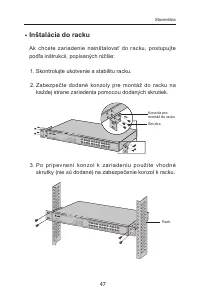
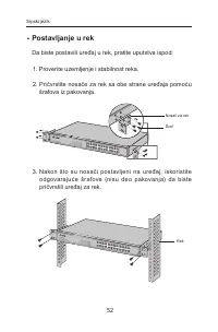
Page 225 - Appendix C: Load Software using FTP; Hardware Installation
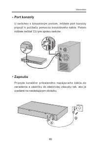
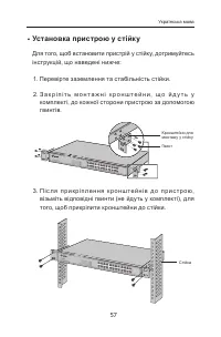
Appendix C: Load Software using FTP If there is something wrong with the firmware of the switch and the switch cannot be launched, you can load firmware to the switch via FTP function. FTP (File Transfer Protocol), a protocol in the application layer, is mainly used to transfer files between the rem...
Page 226 - Figure C-3 Connection Description
Figure C-2 Open Hyper Terminal 2 ) The Connection Description Window will prompt shown as Figure C-3. Enter a name into the Name field and click OK . Figure C-3 Connection Description 3 ) Select the port to connect in the following figure and then click OK . 217
Page 227 - Download Firmware via bootUtil menu; terminal. Connect FTP server to port 1 of the switch.
Figure C-4 Select the port to connect 4 ) Configure the port selected in the step above shown as the following figure. Configure Bits per second as 38400, Data bits as 8, Parity as None, Stop bits as 1, Flow control as None, and then click OK . Figure C-5 Port Settings 3. Download Firmware via bootU...
Page 228 - upgrade
Figure C-6 bootUtil Menu As the prompt is displayed for a short time, you are suggested not to release the CTRL-B key until you enter into bootUtil menu after powering on the switch. 3 ) After entering into bootUtil menu, please firstly configure the IP parameters of the switch. The format is: ifcon...
Page 229 - start; User Access Login
[TP-LINK] : start Start . . . . . . . . . . * * * * * * * * * * * * * * * * * * * * * * User Access Login * * * * * * * * * * * * * * * * * * * * * * User : Return to CONTENTS 220
Page 230 - Guide; Next
Appendix D: 802.1X Client Software In 802.1X mechanism, the supplicant Client should be equipped with the corresponding client software complied with 802.1X protocol standard for 802.1X authentication. When the switch TL-SG3216 works as the authenticator system, please take the following instruction...
Page 232 - Finish; to complete the installation.
Figure D-5 Install the Program 6) The InstallShield Wizard is installing TpSupplicant-V2.0 shown as the following screen. Please wait. Figure D-6 Setup Status 7) On the following screen, click Finish to complete the installation. 223
Page 233 - Figure D-7 InstallShield Wizard Complete; Software; , shown as the following; Cancel
Figure D-7 InstallShield Wizard Complete Note: Please pay attention to the tips on the above screen. If you have not installed WinPcap 4.0.2 or the higher version on your computer, the 802.1X Client Software TpSupplicant can not work. It’s recommended to go to http://www.winpcap.org to download the ...
Page 238 - Appendix E: Glossary; Differentiated Services Code Point (DSCP)
Appendix E: Glossary Access Control List (ACL) ACLs can limit network traffic and restrict access to certain users or devices by checking each packet for certain IP or MAC (i.e., Layer 2) information. Boot Protocol (BOOTP) BOOTP is used to provide bootup information for network devices, including IP...
Page 241 - A TCP/IP protocol commonly used for software downloads.
232 Secure Shell (SSH) A secure replacement for remote access functions, including Telnet. SSH can authenticate users with a cryptographic key, and encrypt data connections between management clients and the switch. Simple Network Management Protocol (SNMP) The application protocol in the Internet s...


 TP-Link EAP225 Wall
User Manual
TP-Link EAP225 Wall
User Manual
 TP-Link LS1005
User Manual
TP-Link LS1005
User Manual
 TP-Link LS1008G
User Manual
TP-Link LS1008G
User Manual
 TP-Link LS105G
User Manual
TP-Link LS105G
User Manual
 TP-Link LS108G
User Manual
TP-Link LS108G
User Manual
 TP-Link Omada OC300
User Manual
TP-Link Omada OC300
User Manual
 TP-Link TL-SF1005LP
User Manual
TP-Link TL-SF1005LP
User Manual
 TP-Link TL-SF1005P
User Manual
TP-Link TL-SF1005P
User Manual
 TP-Link TL-SF1006P
User Manual
TP-Link TL-SF1006P
User Manual
 TP-Link TL-SF1008LP
User Manual
TP-Link TL-SF1008LP
User Manual
 TP-Link TL-SF1009P
User Manual
TP-Link TL-SF1009P
User Manual
 TP-Link TL-SG1005LP
User Manual
TP-Link TL-SG1005LP
User Manual
 TP-Link TL-SG1005P
User Manual
TP-Link TL-SG1005P
User Manual
 TP-Link TL-SG1008D
User Manual
TP-Link TL-SG1008D
User Manual