Page 2 - Copyright; Toshiba Personal Computer Satellite M40X Maintenance Manual; Disclaimer
ii [CONFIDENTIAL] Satellite M40X Maintenance Manual Copyright © 2004 by Toshiba Corporation. All rights reserved. Under the copyright laws, this manual cannot be reproduced in any form without the prior written permission of Toshiba. No patent liability is assumed with respect to the use of the info...
Page 3 - Preface; SAFETY PRECAUTIONS; serious bodily injury if the safety instruction is not observed.
Satellite M40X Maintenance Manual [CONFIDENTIAL] iii Preface This maintenance manual describes how to perform hardware service maintenance for the Toshiba Personal Computer Satellite SATELLITE M40X, referred to as the M40X Series in this manual. The procedures described in this manual are intended t...
Page 5 - Conventions; Acronyms; boldface; Key operation; Ctrl; and at the same time press
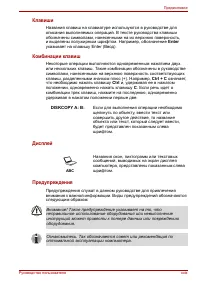
Satellite M40X Maintenance Manual [CONFIDENTIAL] v Conventions This manual uses the following formats to describe, identify, and highlight terms and operating procedures. Acronyms On the first appearance and whenever necessary for clarification acronyms are enclosed in parentheses following their de...
Page 7 - Table of Contents; Chapter 1
Satellite M40X Maintenance Manual [CONFIDENTIAL] vii Table of Contents Chapter 1 Hardware Overview 1.1 Features............................................................................................................................. 1-1 1.2 System Unit ..............................................
Page 8 - Chapter 3
viii [CONFIDENTIAL] Satellite M40X Maintenance Manual Chapter 3 Tests and Diagnostics 3.1 The Diagnostic Test ............................................................................................................3-1 3.2 Executing the Diagnostic Test................................................
Page 9 - Chapter 4
Satellite M40X Maintenance Manual [CONFIDENTIAL] ix Chapter 4 Replacement Procedures 4.1 General.............................................................................................................................. 4-1 4.2 Battery.................................................................
Page 10 - Appendices
x [CONFIDENTIAL] Satellite M40X Maintenance Manual Appendices Appendix A Handling the LCD Module ..................................................................................... A-1 Appendix B Board Layout ............................................................................................
Page 12 - Hardware Overview
1 Hardware Overview 1-ii [CONFIDENTIAL] Satellite M40X Maintenance Manual
Page 14 - Figures
1 Hardware Overview 1-iv [CONFIDENTIAL] Satellite M40X Maintenance Manual Figures Figure 1-1 2.5-inch HDD .............................................................................................. 1-11 Table Table 1-1 2.5-inch HDD specifications .....................................................
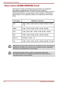
Page 21 - Items; Bytes per sector
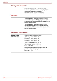
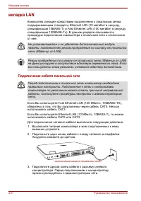
1.3 -inch Hard Disk Drive 1 Hardware Overview Satellite M40X Series Maintenance Manual [CONFIDENTIAL] 1-11 1.3 2.5-inch Hard Disk Drive The internal HDD is a random access non-volatile storage device. It has a non-removable 2.5-inch magnetic disk and mini-Winchester type magnetic heads. The computer...
Page 22 - Optical device Drives; DVD Super Multi drive; Item; Average random access
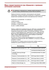
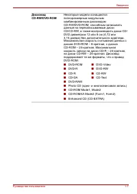
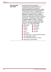
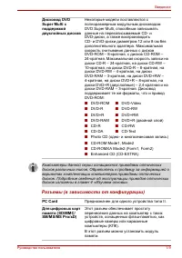
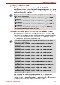
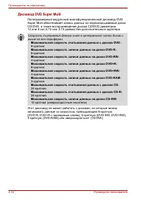
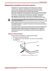
1 Hardware Overview 1.4 Optical device Drives 1-12 [CONFIDENTIAL] Satellite M40X Maintenance Manual 1.4 Optical device Drives ? DVD-ROM & CD-RW drive ? DVD Super Multi drive 1.4.1 DVD-ROM & CD-RW The DVD Super Multi drive accepts 12-cm (4.72- inch) and 8-cm (3.15- inch) discs. At maximum, th...
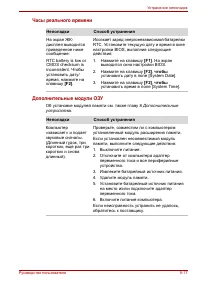
Page 27 - RTC battery
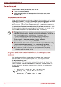
1.6 Batteries 1 Hardware Overview Satellite M40X Series Maintenance Manual [CONFIDENTIAL] 1-17 1.6 Batteries The computer has two types of batter y: ? Main battery pack (18650 size) ? RTC battery The removable main battery pack is the computer’s main power source when the AC adaptor is not attached....
Page 28 - NOTES
1 Hardware Overview 1.6 Batteries 1-18 [CONFIDENTIAL] Satellite M40X Maintenance Manual 1.6.1 Main Battery Battery charging is controlled by a power supply microprocessor that is mounted on the system board. The power supply microprocessor controls whether the charge is on or off and detects a full ...
Page 31 - Troubleshooting Procedures
2 Troubleshooting Procedures 2-ii [CONFIDENTIAL] Satellite M40X/M45X /Satellite Pro M40X /EQUIUM M40X Series Maintenance Manual l
Page 32 - Chapter 2
2 Troubleshooting Procedures Satellite M40X/M45X /Satellite Pro M40X /EQUIUM M40X Series Maintenance Manual [CONFIDENTIAL] 2-iii Chapter 2 Contents 2.1 Troubleshooting Introduction .................................................................................... 2-1 2.2 Troubleshooting Flowchart ...
Page 34 - Troubleshooting Introduction; . Wireless LAN system
2.1 Troubleshooting Introduction 2 Troubleshooting Procedures Satellite M40X/M45X /Satellite Pro M40X /EQUIUM M40X Series Maintenance Manual [CONFIDENTIAL] 2-1 2.1 Troubleshooting Introduction Chapter 2 describes how to determine if a Field Replaceable Unit (FRU) in the computer is causing the compu...
Page 35 - Troubleshooting Flowchart; Make sure all optional equipment is removed from the computer.
2 Troubleshooting Procedures 2.3 Power Supply Troubleshooting 2-2 [CONFIDENTIAL] Satellite M40X/M45X /Satellite Pro M40X /EQUIUM M40X Series Maintenance Manual 2.2 Troubleshooting Flowchart If you know the location of the malfunction, turn directly to the appropriate section of this chapter. If the ...
Page 40 - Power Supply Troubleshooting; Figure 2-2 Power Supply Troubleshooting Process
2.3 Power Supply Troubleshooting 2 Troubleshooting Procedures Satellite M40X/M45X /Satellite Pro M40X /EQUIUM M40X Series Maintenance Manual [CONFIDENTIAL] 2-7 2.3 Power Supply Troubleshooting S T A R T A r e t h e D C - I N a n d B a t t e r y L E D s l i t ? C a n y o u t u r n t h e c o m p u t e...
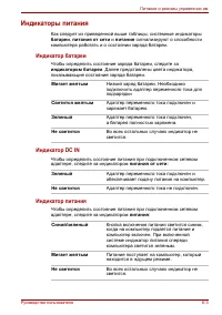
Page 41 - Procedure 1; Table 2-1 Battery LED; Battery State
2 Troubleshooting Procedures 2.3 Power Supply Troubleshooting 2-8 [CONFIDENTIAL] Satellite M40X/M45X /Satellite Pro M40X /EQUIUM M40X Series Maintenance Manual The power supply controls many functions and components. To determine if the power supply is functioning properly, start with Procedure 1 an...
Page 42 - Power supply status
2.3 Power Supply Troubleshooting 2 Troubleshooting Procedures Satellite M40X/M45X /Satellite Pro M40X /EQUIUM M40X Series Maintenance Manual [CONFIDENTIAL] 2-9 Table 2-2 DC-IN LED AC-IN LED Power supply status Solid on AC power exists (LED is solid green). Off No AC power exists. To check the power ...
Page 43 - Procedure 3
2 Troubleshooting Procedures 2.3 Power Supply Troubleshooting 2-10 [CONFIDENTIAL] Satellite M40X/M45X /Satellite Pro M40X /EQUIUM M40X Series Maintenance Manual Procedure 3 Power supply connection check The power supply wiring diagram is shown below: AC adaptor System board Battery AC adaptor cord A...
Page 44 - Procedure 4; Reinstall the battery pack.; Procedure 5; Replacement Procedures
2.3 Power Supply Troubleshooting 2 Troubleshooting Procedures Satellite M40X/M45X /Satellite Pro M40X /EQUIUM M40X Series Maintenance Manual [CONFIDENTIAL] 2-11 Procedure 4 Diagnostic check The power supply may not charge the battery pack. Perform the following procedures: 1. Reinstall the battery p...
Page 45 - Display Troubleshooting; Figure 2-3 Display troubleshooting process
2 Troubleshooting Procedures 2.4 Display Troubleshooting 2-12 [CONFIDENTIAL] Satellite M40X/M45X /Satellite Pro M40X /EQUIUM M40X Series Maintenance Manual 2.4 Display Troubleshooting P e r f o r m e x t e r n a l d i s p l a y c h e c k ( P r o c e d u r e 1 ) S T A R T D o e s t h e e x t e r n a ...
Page 46 - Procedure 1: External display check; Tests and Diagnostics
2.4 Display Troubleshooting 2 Troubleshooting Procedures Satellite M40X/M45X /Satellite Pro M40X /EQUIUM M40X Series Maintenance Manual [CONFIDENTIAL] 2-13 This section describes how to determine if the computer’s display is functioning properly. The process is outlined in Figure 2-3. Start with Pro...
Page 47 - Replacement Procedures,
2 Troubleshooting Procedures 2.4 Display Troubleshooting 2-14 [CONFIDENTIAL] Satellite M40X/M45X /Satellite Pro M40X /EQUIUM M40X Series Maintenance Manual Procedure 3 Connector and replacement check The FL inverter board, LCD module, and system board are connected to the display c ircuits. Any of t...
Page 48 - Keyboard Troubleshooting; Figure 2-4 Keyboard troubleshooting process
2.5 Keyboard Troubleshooting 2 Troubleshooting Procedures Satellite M40X/M45X /Satellite Pro M40X /EQUIUM M40X Series Maintenance Manual [CONFIDENTIAL] 2-15 2.5 Keyboard Troubleshooting P e r f o r m e x t e r n a l k e y b o a r d c h e c k ( P r o c e d u r e 1 ) S T A R T D o e s t h e e x t e r ...
Page 50 - External USB Devices Troubleshooting; Figure 2-5 External USB device troubleshooting process
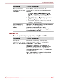
2.6 External USB Devices Troubleshooting 2 Troubleshooting Procedures Satellite M40X/M45X /Satellite Pro M40X /EQUIUM M40X Series Maintenance Manual [CONFIDENTIAL] 2-17 2.6 External USB Devices Troubleshooting R e p l a c e s y s t e m b o a r d ( P r o c e d u r e 2 ) E N D O r i g i n a l U S B d ...
Page 52 - Figure 2-6 TV-out troubleshooting process
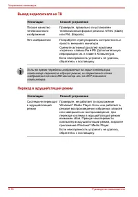
2.7 TV-Out Failure Troubleshooting 2 Troubleshooting Procedures Satellite M40X/M45X /Satellite Pro M40X /EQUIUM M40X Series Maintenance Manual [CONFIDENTIAL] 2-19 2.7 TV-Out Failure Troubleshooting P e r f o r m T V c o n n e c t i o n c h e c k ( P r o c e d u r e 1 ) S T A R T D o e s r e p l a c ...
Page 54 - Printer Port Troubleshooting; Figure 2-7 Printer port troubleshooting process
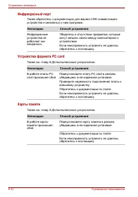
2.8 Printer Port Troubleshooting 2 Troubleshooting Procedures Satellite M40X/M45X /Satellite Pro M40X /EQUIUM M40X Series Maintenance Manual [CONFIDENTIAL] 2-21 2.8 Printer Port Troubleshooting S T A R T Perform diagnostic check (Procedure 1) Does the print port function ok? Perform print port loopb...
Page 56 - TouchPad Troubleshooting; Figure 2-8 TouchPad troubleshooting process
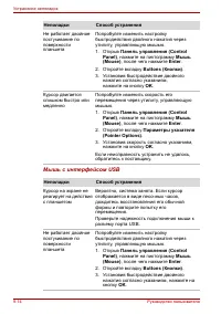
2.9 Touch Pad Troubleshooting 2 Troubleshooting Procedures Satellite M40X/M45X /Satellite Pro M40X /EQUIUM M40X Series Maintenance Manual [CONFIDENTIAL] 2-23 2.9 TouchPad Troubleshooting S TART END TouchPad connection check (Procedure 1) TouchPad replacement check (Procedure 2) Replace system board ...
Page 57 - Procedure 1: TouchPad connection check; Procedure 2
2 Troubleshooting Procedures 2.9 TouchPad Troubleshooting 2-24 [CONFIDENTIAL] Satellite M40X/M45X /Satellite Pro M40X /EQUIUM M40X Series Maintenance Manual To determine if the computer’s built- in TouchPad is functioning properly, perform the following procedures. Figure 2-9 outlines the process. S...
Page 58 - Speaker Troubleshooting; Figure 2-9 Speaker troubleshooting process
2.10 Speaker Troubleshooting 2 Troubleshooting Procedures Satellite M40X/M45X /Satellite Pro M40X /EQUIUM M40X Series Maintenance Manual [CONFIDENTIAL] 2-25 2.10 Speaker Troubleshooting S TART Do all sources have same problem? END Perform earphone test (Procedure 2) Do earphones function correctly? ...
Page 59 - Procedure 1: Audio source test
2 Troubleshooting Procedures 2.10 Speaker Troubleshooting 2-26 [CONFIDENTIAL] Satellite M40X/M45X /Satellite Pro M40X /EQUIUM M40X Series Maintenance Manual To determine if the computer’s built- in speakers are functioning properly, perform the following procedures. Figure 2-10 outlines the process....
Page 60 - Optical Drive Troubleshooting; Figure 2-10 Optical drive troubleshooting process
2.11 Optical Drive Troubleshooting 2 Troubleshooting Procedures Satellite M40X/M45X /Satellite Pro M40X /EQUIUM M40X Series Maintenance Manual [CONFIDENTIAL] 2-27 2.11 Optical Drive Troubleshooting START Audio CD functions ok? END Perform software check (Procedure 3) Perform diagnostic test (Procedu...
Page 62 - Replacement Procedures
2.11 Optical Drive Troubleshooting 2 Troubleshooting Procedures Satellite M40X/M45X /Satellite Pro M40X /EQUIUM M40X Series Maintenance Manual [CONFIDENTIAL] 2-29 Procedure 5 Connection check and replacement check The optical drive connects to the system board. The drive may be disconnected, or the ...
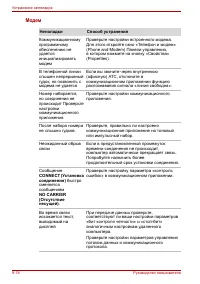
Page 63 - Modem Troubleshooting; Figure 2-11 Modem troubleshooting process
2 Troubleshooting Procedures 2.12 Modem Troubleshooting 2-30 [CONFIDENTIAL] Satellite M40X/M45X /Satellite Pro M40X /EQUIUM M40X Series Maintenance Manual 2.12 Modem Troubleshooting START Computer unable to detect telephone signal? END Perform connection check (Procedure 2) Perform replacement check...
Page 64 - Procedure 1: Telephone line connection check
2.13 Modem Troubleshooting 2 Troubleshooting Procedures Satellite M40X/M45X /Satellite Pro M40X /EQUIUM M40X Series Maintenance Manual [CONFIDENTIAL] 2-31 This section describes how to determine if the computer's modem is functioning properly. Figure 2-12 outlines the process. Perform the steps belo...
Page 65 - PCMCIA Troubleshooting; Figure 2-12 PCMCIA troubleshooting process
2 Troubleshooting Procedures 2.13 PCMCIA Troubleshooting 2-32 [CONFIDENTIAL] Satellite M40X/M45X /Satellite Pro M40X /EQUIUM M40X Series Maintenance Manual 2.13 PCMCIA Troubleshooting START Do errors occur during SYCARD test? Perform PCMCIA socket replacement check (Procedure 2) Replace system board...
Page 66 - Procedure 1: Sycard test
2.13 PCMCIA Troubleshooting 2 Troubleshooting Procedures Satellite M40X/M45X /Satellite Pro M40X /EQUIUM M40X Series Maintenance Manual [CONFIDENTIAL] 2-33 This section describes how to determine if the PCMCIA card player is functioning properly. The process is summarized in Figure 2-13. Perform the...
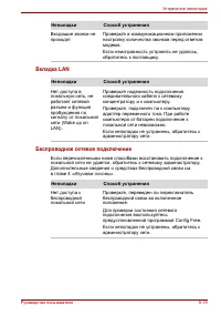
Page 69 - Wireless LAN Troubleshooting; Figure 2-14 Wireless LAN troubleshooting process
2 Troubleshooting Procedures 2.15 Wireless LAN Troubleshooting 2-36 [CONFIDENTIAL] Satellite M40X/M45X /Satellite Pro M40X /EQUIUM M40X Series Maintenance Manual 2.15 Wireless LAN Troubleshooting START Perform diagnostic test (Procedure 1) Was a wireless LAN problem delected? Perform connector and r...
Page 70 - Procedure 1 : Diagnostic test
2.15 Wireless LAN Troubleshooting 2 Troubleshooting Procedures Satellite M40X/M45X /Satellite Pro M40X /EQUIUM M40X Series Maintenance Manual [CONFIDENTIAL] 2-37 The wireless LAN antenna wire, wireless LAN unit or system board may each be the source of a wireless LAN fault. Any of these components m...
Page 72 - Test s and Diagnostics
3. Test s and Diagnostics 3-ii [CONFIDENTIAL] Satellite M40X/M45X/Satellite Pro M40X/EQUIUM M40X Series Maintenance Manual
Page 73 - Test and Diagnostic Operation; Contents
Test and Diagnostic Operation Satellite M40X/M45X/Satellite Pro M40X/EQUIUM M40X Series Maintenance Manual [CONFIDENTIAL] 3-iii Contents 3.1 The Diagnostic Test............................................................................................................ 3-1 3.2 Executing the Diagnosti...
Page 75 - The Diagnostic Test; To start the diagnostics, follow these steps
3.1 The Diagnostic Test 3. Test s and Diagnostics Satellite M40X/M45X/Satellite Pro M40X/EQUIUM M40X Series Maintenance Manual [CONFIDENTIAL] 3-1 3.1 The Diagnostic Test This chapter explains how to use the Test & Diagnostic program to test the functions of the computer’s hardware modules. The T...
Page 76 - Executing the Diagnostic Test; NOTE
3. Test s and Diagnostics 3.2 Executing the Diagnostic Test 3-2 [CONFIDENTIAL] Satellite M40X/M45X/Satellite Pro M40X/EQUIUM M40X Series Maintenance Manual 3.2 Executing the Diagnostic Test Toshiba MS-DOS is required to run the DIAGNOSTICS PROGRAM. To start the DIAGNOSTIC PROGRAM, follow these steps...
Page 80 - Config Check Test; The config check test checks unit configuration. It includes:; green
3. Test s and Diagnostics 3.3 Config Check Test 3-6 [CONFIDENTIAL] Satellite M40X/M45X/Satellite Pro M40X/EQUIUM M40X Series Maintenance Manual 3.3 Config Check Test The config check test checks unit configuration. It includes: ? CPU type ? System memory size ? ODD type ? HDD type & capacity ? B...
Page 82 - PIO Loopback Test; External Interrupt
3. Test s and Diagnostics 3.5 PIO Loopback Test 3-8 [CONFIDENTIAL] Satellite M40X/M45X/Satellite Pro M40X/EQUIUM M40X Series Maintenance Manual 3.5 PIO Loopback Test The PIO loopback test will check below items through PIO loopback connector. ? External Interrupt ? External Loopback - including Patt...
Page 84 - Speaker Audio Test
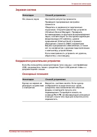
3. Test s and Diagnostics 3.7 Speaker Audio Test 3-10 [CONFIDENTIAL] Satellite M40X/M45X/Satellite Pro M40X/EQUIUM M40X Series Maintenance Manual 3.6 Speaker Audio Test The speaker audio test allows the user to aurally confirm the speaker functions. And check both speakers if they are OK within 3 ti...
Page 86 - Main Battery Charge Test
3. Test s and Diagnostics 3.9 Main Battery Change Test 3-12 [CONFIDENTIAL] Satellite M40X/M45X/Satellite Pro M40X/EQUIUM M40X Series Maintenance Manual 3.8 Main Battery Charge Test NOTE : The AC adaptor ( 120W/90W, 19V ) should be connected to successfully run this test. This test shows and measures...
Page 88 - Tests and Diagnostics
3 Tests and Diagnostics 3.10 FDD Test 3-14 [CONFIDENTIAL] Satellite M40X/M45X/Satellite Pro M40X/EQUIUM M40X Series Maintenance Manual
Page 90 - The keyboard test checks the all keys function.
3. Test s and Diagnostics 3.12 Keyboard Test 3-16 [CONFIDENTIAL] Satellite M40X/M45X/Satellite Pro M40X/EQUIUM M40X Series Maintenance Manual 3.11 Keyboard Test The keyboard test checks the all keys function. NOTE: The Num Lock and the Overlay mode must be off to execute the keyboard test. Before ke...
Page 92 - Pressing a key also reveals that key’s; scan codes; in the upper right hand corner of the screen. When; make code; is displayed. When the key is released, the; break code
3. Test s and Diagnostics 3.12 Keyboard Test 3-18 [CONFIDENTIAL] Satellite M40X/M45X/Satellite Pro M40X/EQUIUM M40X Series Maintenance Manual Pressing a key also reveals that key’s scan codes in the upper right hand corner of the screen. When the key is depressed, its make code is displayed. When th...
Page 95 - LCD Pixels Mode Test; This LCD pixels mode test checks whether video display is fine.
3.14 LCD Pixels Mode Test 3. Test s and Diagnostics Satellite M40X/M45X/Satellite Pro M40X/EQUIUM M40X Series Maintenance Manual [CONFIDENTIAL] 3-21 3.13 LCD Pixels Mode Test This LCD pixels mode test checks whether video display is fine. This test includes two modes of the test: 1. Text Mode - incl...
Page 96 - Lid Switch Test
3. Tests and Diagnostics 3.15 Lid Switch Test 3-22 [CONFIDENTIAL] Satellite M40X/M45X/Satellite Pro M40X/EQUIUM M40X Series Maintenance Manual 3.14 Lid Switch Test The lid switch test checks the lid function of the unit. When LCD cover closed, the lid should enable to turn off the display. NOTE : Re...
Page 97 - TOSHIBA
3.16 HDD R/W Test 3. Test s and Diagnostics Satellite M40X/M45X/Satellite Pro M40X/EQUIUM M40X Series Maintenance Manual [CONFIDENTIAL] 3-23 3.15 HDD R/W Test The HDD R/W test allows the user to test aurally HDD read/write function. For data security concern, it is necessary to input password - “ TO...
Page 104 - Replacement Procedures
4 Replacement Procedures 4-ii [CONFIDENTIAL] Satellite M40X Series Maintenance Manual
Page 110 - Safety Precautions; To avoid the risk of electric shock or other injury:
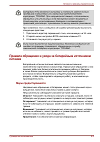
4 Replacement Procedures Safety Precautions Before you begin disassembly, read the following safety precautions and observe them carefully as you work. DANGER: 1. Always use the lithium ion battery pack or backup battery that is authorized by Toshiba or compatible with the unit. Since other battery ...
Page 111 - Before You Begin
4 Replacement Procedures Before You Begin Look over the procedures in this section before you begin disassembling the computer. Familiarize yourself with the disassembly and reassembly steps. Begin each procedure by removing the AC adaptor and the battery pack as instructed in section 4.2. 1. Do not...
Page 112 - Disassembly Procedures
4 Replacement Procedures Disassembly Procedures The computer has two basic types of cable connectors: Pressure Plate Connectors Standard Pin Connectors To disconnect a Pressure Plate connector, lift up the tabs on either side of the connector’s plastic pressure plate and slide the cable out of the c...
Page 113 - Tools and Equipment; One M2 Phillips screwdriver to remove and replace screws.
4 Replacement Procedures Tools and Equipment The use of Electrostatic Discharge (ESD) equipment is very important for your safety and the safety of those around you. Proper use of these devices will increase the success rate of your repairs and lower the cost for damaged or destroyed parts. The foll...
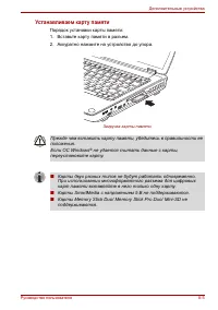
Page 114 - Removing the Battery Pack; Then you can remove it from the bay.
4 Replacement Procedures 4.2 Battery Removing the Battery Pack To remove the battery pack from the battery bay, follow the steps below. 1. Turn the computer upside down. 2. Unlock the battery double lock and slide the battery bay latch to release the battery pack. Then you can remove it from the bay...
Page 115 - Installing the Battery Pack
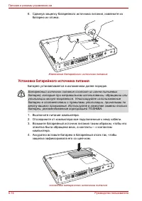
4 Replacement Procedures Installing the Battery Pack To install the battery pack in the battery bay, follow the steps below and refer to the figure in the preceding section. WARNING: The battery is a lithium ion battery and can explode if not properly replaced, used, handled or disposed of. Use only...
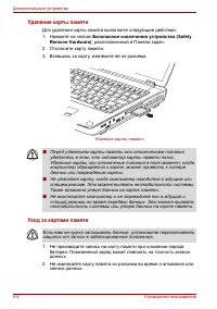
Page 116 - Card; Removing a PC Card; To remove a PC Card, follow the steps below.
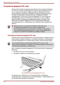
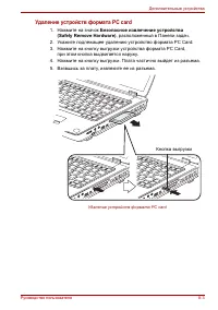
4 Replacement Procedures 4.3 PC Card Removing a PC Card To remove a PC Card, follow the steps below. 1. Push the PC Card’s eject button. The button pops out when you release it. 2. Push the eject button again to pop the PC Card out slightly. 3. Grasp the PC Card and remove it. 4. Push the eject butt...
Page 117 - Installing the PC Card; Make sure the eject button does not stick out.
4 Replacement Procedures Installing the PC Card To install the PC Card, follow the steps below and refer to the figures in the preceding section. 1. Make sure the eject button does not stick out. 2. Insert the PC Card and press gently to ensure a firm connection. Figure 4-3 Installing the PC card 4-...
Page 118 - Removing the HDD Module; Follow the steps below to remove HDD module:
4 Replacement Procedures 4.4 HDD CAUTION : When handling the HDD, do not press the top surface as shown by the arrow. Hold it by the sides. Figure 4-4 HDD Removing the HDD Module Follow the steps below to remove HDD module: 1. 2. 3. Turn the computer upside down Remove a black M2.5x5 screw to releas...
Page 119 - Installing the HDD; Seat the HDD in the HDD case and bracket, and secure it with two M3
4 Replacement Procedures Installing the HDD To install the HDD, follow the steps below and refer to the figures in the preceding section. 1. Seat the HDD in the HDD case and bracket, and secure it with two M3 × 3 black screws. 2. Insert the HDD unit into the HDD slot. 3. Secure the HDD door with a b...
Page 120 - Optical Drive Module; Removing the Optical Drive Module; Remove the screw M2.5x5 securing the optical drive module.
4 Replacement Procedures 4.5 Optical Drive Module Removing the Optical Drive Module To remove the optical drive module, you need to remove the keyboard first. Follow the steps below: 1. Turn the computer upside down. 2. Remove the screw M2.5x5 securing the optical drive module. 3. Use your hand to p...
Page 121 - Installing the Optical Drive Module; Slide the device into the optical drive module bay.
4 Replacement Procedures Installing the Optical Drive Module To install a device in the optical drive module bay, follow the steps below and refer to the figure in the preceding section. 1. Slide the device into the optical drive module bay. 2. Use the screw M2.5x5 to secure the optical drive module...
Page 122 - Drive; This computer may be fitted with a:; Disassembling the Optical Drive; Removing the optical drive bracket
4 Replacement Procedures 4.6 Optical Drive This computer may be fitted with a: CD-RW/DVD-ROM device DVD dual device DVD Super Multi device Disassembling the Optical Drive To disassemble the optical drive, first remove the drive from its module bay, then follow the steps below. 1. Remove one M2.5x5 s...
Page 123 - Reassembling the Optical Drive; Secure the optical drive bracket plate with two black M2
4 Replacement Procedures Reassembling the Optical Drive To reassemble an optical drive, follow the steps below and refer to the figure in the preceding section. 1. Position the optical drive bracket plate to the rear panel of optical drive. 2. Secure the optical drive bracket plate with two black M2...
Page 124 - Removing the Keyboard; Follow the steps below to remove the keyboard:
4 Replacement Procedures 4.7 Keyboard Removing the Keyboard Follow the steps below to remove the keyboard: 1. Open the display panel. 2. Insert a thin tool into the gap between the strip cover and keyboard to lever the strip cover up and then release the strip cover. Figure 4-8 Removing the strip co...
Page 126 - Installing the Keyboard; Connect the keyboard cable to the system board.
4 Replacement Procedures Installing the Keyboard To install the keyboard, follow the steps below and refer to the figures in the preceding section. 1. Connect the keyboard cable to the system board. 2. Set the keyboard in place and secure it with two M2 x 2 black screws. 3. Set the strip cover and p...
Page 127 - Wireless LAN Unit; Removing the Wireless LAN Unit; Figure 4-11 Removing the wireless LAN door
4 Replacement Procedures 4.8 Wireless LAN Unit Removing the Wireless LAN Unit To remove wireless LAN unit, you must remove strip cover and keyboard first, then follow the steps below to remove wireless LAN unit. 1. Remove the embedded screw securing the wireless LAN door, and then remove the wireles...
Page 128 - Installing the Wireless LAN Unit; CAUTION
4 Replacement Procedures Figure 4-12 Removing the wireless LAN unit CAUTION : Do not touch the connectors on the wireless LAN unit or on the computer. Debris on the connectors may cause malfunction. Installing the Wireless LAN Unit To install the wireless LAN unit, follow the steps below and refer t...
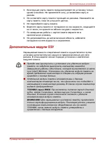
Page 129 - Memory; Removing the Expansion Memory; securing the memory module socket cover.
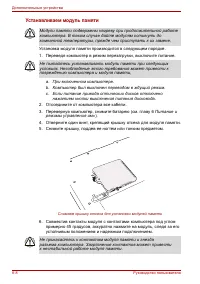
4 Replacement Procedures 4.9 Expansion Memory Removing the Expansion Memory To remove the memory module, make sure the computer is in boot mode then: 1. Be sure the power is off and all cables are disconnected from the computer. 2. Turn the computer upside down and remove the battery and loosen the ...
Page 130 - Installing the Expansion Memory
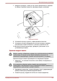
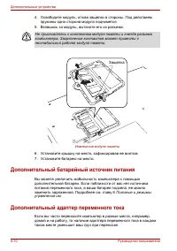
4 Replacement Procedures Installing the Expansion Memory CAUTION : Do not touch the connectors on the expansion memory or on the computer. Debris on the connectors may cause memory access problems. Follow these steps to install a memory module: 1. Set the computer to boot mode and turn off the power...
Page 132 - Removing the Modem; Loosen the safety screw to release the modem cover.
4 Replacement Procedures 4.10 Modem Removing the Modem To remove the installed modem, first remove the strip cover and keyboard, then follow the steps below: 1. Loosen the safety screw to release the modem cover. 2. Remove two M2.5x5 screws securing the modem module. 3. Carefully lift the unit off i...
Page 133 - Installing the Modem; Connect the modem cable to the modem module.
4 Replacement Procedures Installing the Modem To install a modem, follow the steps below and refer to the figures in the preceding section. 1. Connect the modem cable to the modem module. 2. Fit the modem onto its connector and secure it with two black M2.5x5 screws. 3. Replace the keyboard and stri...
Page 134 - Display Assembly; Removing the Display Assembly; Disconnect the wireless LAN antenna from the top chassis.
4 Replacement Procedures 4.11 Display Assembly Removing the Display Assembly To remove the display assembly, first remove the keyboard and wireless LAN, then follow the steps below: 1. Remove the strip cover and then remove the two black screws M2x2 securing the keyboard. 2. Disconnect the wireless ...
Page 136 - Installing the Display Assembly; computer’s back side (which help hold the display assembly in place).
4 Replacement Procedures Installing the Display Assembly To install the display assembly, follow the steps below and refer to the figures in the preceding section. 1. Seat the display assembly taking care not to crush to the LCD display cable, the LCD power cable, or wireless LAN antenna. 2. Secure ...
Page 137 - Removing the Cover; Remove modem and wireless LAN covers.
4 Replacement Procedures 4.12 Top Cover Removing the Cover To remove the top cover, first remove the battery pack, display assembly, optical drive module, HDD, and memory module and wireless LAN as described in the preceding sections, then follow the steps below: 1. Remove modem and wireless LAN cov...
Page 139 - Installing the Top Cover; computer’s top chassis.
4 Replacement Procedures Installing the Top Cover To install the top cover, follow the steps below and refer to the figures in the preceding section. 1. Seat the top cover and secure the upper FFC cable and Touch pad FFC cable to the computer’s top chassis. 2. Secure the top cover with one M2.5x10 s...
Page 140 - Disconnect the Touch Pad FFC cable from the Touch Pad.
4 Replacement Procedures 4.13 Touch Pad Removing the Cover To remove the Touch Pad, first remove the top cover, then follow the steps below: 1. Disconnect the Touch Pad FFC cable from the Touch Pad. 2. Remove one M2.5x3 screw securing the Track Pad Bracket. Slide it and Lift out the Track Pad Bracke...
Page 141 - Installing the Touch Pad; Connect the Touch Pad LED FFC cable to the Touch Pad.
4 Replacement Procedures Installing the Touch Pad To install the Touch Pad, follow the steps below and refer to the figures in the preceding section: 1. With the top cover upside down, place the Touch Pad, the Track Pad Bracket, and LED PCB board in position. 2. Secure the LED PCB board with two M2....
Page 142 - Removing the Speakers; Tear off the stickers securing the cables to the fixed places.; Installing the Speakers; Attached the speaker cable to the system board.
4 Replacement Procedures 4.14 Speakers Removing the Speakers To remove the speakers, first remove the top cover, then follow the steps below: 1. Tear off the stickers securing the cables to the fixed places. 2. Remove the two M2.5x5 screws and then disconnect the speaker cable from the speakers. Fig...
Page 143 - Removing the System Board; Remove the thermal plate and audio FCC cable.
4 Replacement Procedures 4.15 System Board Removing the System Board To remove the system board, first remove the LCD assembly, top cover and HDD, then follow the steps below: 1. Remove the thermal plate and audio FCC cable. 2. Remove four thermal screws to release thermal module. 3. Remove the ther...
Page 144 - Installing the System Board; Seat the system board in the chassis.
4 Replacement Procedures Installing the System Board To install the system board, follow the steps below and refer to the figures in the preceding section. 1. Seat the system board in the chassis. 2. Connect the thermal cable. 3. Replace the thermal module and secure it with four thermal screws. 4. ...
Page 145 - Removing the Fan & CPU; the stress on the CPU below.
4 Replacement Procedures 4.16 Fan & CPU Removing the Fan & CPU To remove the Fan, Heat Sink, and CPU, you must first remove the panel, keyboard, top cover and bottom chassis to reveal the system board, then follow the steps below: 1. Remove three screws from the VGA plate (Two security screw...
Page 147 - Installing the CPU; Make sure that the notch on the cam is aligned with the
4 Replacement Procedures Installing the CPU To install the CPU, follow the steps below and refer to the figures in the preceding section. CAUTION: If you remove the heat sink, you should use the CPU grease tool to remove the grease on the CPU and heat sink. Reapply fresh grease before installing the...
Page 148 - Removing the Display Mask; Figure 4-28 Removing the display mask
4 Replacement Procedures 4.17 Display Mask Removing the Display Mask To remove the display mask, first remove the display assembly as described earlier, then follow the steps below: 1. Remove the mask seals to expose two lower inner corner screws securing the display mask. 2. Remove two M2.5 × 5 bla...
Page 149 - Installing the Display Mask; Seat the display mask and secure the snaps on each side.
4 Replacement Procedures Installing the Display Mask To install the display mask, follow the steps below and refer to the figures in the preceding section. 1. Seat the display mask and secure the snaps on each side. 2. Secure the display mask with two M2.5x5 screws at the bottom inner corner. 3. Cov...
Page 150 - Removing the LCD Module; Disconnect the LCD cable from the FL inverter board.
4 Replacement Procedures 4.18 LCD Module Removing the LCD Module To remove the LCD module, first remove the display assembly and display mask, then follow the steps below. 1. Remove two M2x3 black screws securing the LCD cable and FL inverter board. 2. Disconnect the LCD cable from the FL inverter b...
Page 151 - Remove the LCD module.
4 Replacement Procedures 4. Remove six M2x3 screws securing LCD module bracket to LCD module. Remove LCD cable. LCD cable M2X3 M2X3 M2.5X5 M2X3 FL inverter board Figure 4-30 Removing the LCD module-2 5. Remove the LCD module. NOTE : If the LCD module malfunctions, remove the LCD cable and LCD bracke...
Page 152 - Installing the LCD Module; Set the LCD module in the display assembly.
4 Replacement Procedures Installing the LCD Module To install the LCD module, follow the steps below and refer to the figures in the preceding section. 1. Set the LCD module in the display assembly. 2. Connect the FL cable and the HV cable to the FL inverter board. 3. Seat the LCD module in the disp...
Page 153 - FL Inverter Board; Removing the FL Inverter Board; Figure 4-31 Removing the FL inverter board; Installing the FL Inverter Board
4 Replacement Procedures 4-46 [CONFIDENTIAL] Satellite M40X Series Maintenance Manual 4.19 FL Inverter Board Removing the FL Inverter Board To remove the FL inverter board, first remove the battery pack, the display assembly, display mask, and LCD module, then follow the steps below. 1. Remove one M...
Page 156 - Appendix
Satellite M40X Series Maintenance Manual [CONFIDENTIAL] App-iii Appendix Contents Appendix A Handling the LCD Module ................................................................................A-1 Appendix B Board Layout ..............................................................................
Page 158 - Tables
Satellite M40X Series Maintenance Manual [CONFIDENTIAL] App-v Tables Table B-1 System board ICs (top and bottom) .....................................................................B-3 Table B-2 System board connectors (top and bottom) .........................................................B-4 Ta...
Page 159 - Appendix A Handling the LCD Module; Precautions for handling the LCD module
Satellite M40X Series Maintenance Manual [CONFIDENTIAL] A-1 Appendix A Appendix A Handling the LCD Module Precautions for handling the LCD module The LCD module can be easily damaged during assembly or disassembly. Therefore, please observe the following precautions when handling it: 1. When install...
Page 165 - Appendix B Board Layout
Satellite M40X Series Maintenance Manual [CONFIDENTIAL] B-1 Appendix B Appendix B Board Layout B.1 System Board (FRDSY*) Bottom View A C D B F G H I L
Page 167 - Mark; BIOS ROM
Satellite M40X Series Maintenance Manual [CONFIDENTIAL] B-3 Table B-1 System board ICs (top and bottom) Mark Number Name A U44 Intel ALVISO BGA-1257 MCH R0.7 B U36 Intel ICH6-M BGA-609 C U40 CLK GEN ICS954226AG TSSOP-56 D U33 KB/EC KB910Q E U10 I/O Controller (LPC47N217-JN) F U43 Cardbus & 5-in-...
Page 168 - Number
B-4 [CONFIDENTIAL] Satellite M40X Series Maintenance Manual Table B-2 System board connectors (top and bottom) Number Name JP2 Parallel Connector JP1 CRT Connector JP3 TV-OUT Connector JP4 RJ11/RJ45 Connector JP5, JP23 USB Connector JP6 LVDS Connector JP7 FAN Connector JP8 HDD Connector JP11 MINI PC...
Page 169 - Battery Connector
Satellite M40X Series Maintenance Manual [CONFIDENTIAL] B-5 PJP2 Battery Connector
Page 170 - Appendix C Pin Assignments; System Board
Satellite M40X Series Maintenance Manual [CONFIDENTIAL] C-1 C . Appendix C Pin Assignments System Board C.1 JP25 Table C-1 SODIMM I/F pin assignments (200-PIN ) (1/4) Pin No. Signal name I/O Pin No. Signal Name I/O 1 VREF O 2 VREF O 3 VSS - 4 VSS - 5 DDR_DQ1 I/O 6 DDR_DQ0 I/O 7 DDR_DQ6 I/O 8 DDR_DQ4...
Page 190 - Appendix D Keyboard Scan/Character Codes
Satellite M40X Series Maintenance Manual [CONFIDENTIAL] D-1 Appendix D Appendix D Keyboard Scan/Character Codes Table D-1 Scan codes (set 1 and set 2) (1/4) Code set 1 Code set 2 Cap No. Keytop Make Break Make Break Note 01 ‘ ~ 29 A9 0E F0 0E 02 1 ! 02 82 16 F0 16 03 2 @ 03 83 1E F0 1E 04 3 # 04 84 ...
Page 193 - * Scan codes differ by overlay function.; key gives different codes.; Fn; key does not generate a code by itself.
D-4 [CONFIDENTIAL] Satellite M40X Series Maintenance Manual Table D-1 Scan codes (set 1 and set 2) (4/4) Code set 1 Code set 2 Cap No. Keytop Make Break Make Break Note 122 F11 57 D7 78 F0 78 *3 123 F12 58 D8 07 F0 07 *3 124 PrintSc *6 *6 *6 *6 *6 126 Pause *7 *7 *7 *7 *7 X Fn — — — — *4 X Win E0 5B...
Page 194 - Table D-2 Scan codes with left Shift key; Shift
Satellite M40X Series Maintenance Manual [CONFIDENTIAL] D-5 Table D-2 Scan codes with left Shift key Code set 1 Code set 2 Cap No. Key top Make Break Make Break 55 / E0 AA E0 35 E0 B5 E0 2A E0 F0 12 E0 4A E0 F0 4A E0 12 75 INS E0 AA E0 52 E0 D2 E0 2A E0 F0 12 E0 70 E0 F0 70 E0 12 76 DEL E0 AA E0 53 ...
Page 195 - Table D-3 Scan codes in Numlock mode
D-6 [CONFIDENTIAL] Satellite M40X Series Maintenance Manual Table D-3 Scan codes in Numlock mode Code set 1 Code set 2 Cap No. Key top Make Break Make Break 75 INS E0 2A E0 52 E0 D2 E0 AA E0 12 E0 70 E0 F0 70 E0 F0 12 76 DEL E0 2A E0 53 E0 D3 E0 AA E0 12 E0 71 E0 F0 71 E0 F0 12 79 ? ? E0 2A E0 4B E0...
Page 196 - Table D-5 Scan codes in overlay mode
Satellite M40X Series Maintenance Manual [CONFIDENTIAL] D-7 Table D-5 Scan codes in overlay mode Code set 1 Code set 2 Cap No. Keytop Make Break Make Break 09 8 (8) 48 C8 75 F0 75 10 9 (9) 49 C9 7D F0 7D 11 0 (*) 37 B7 7C F0 7C 23 U (4) 4B CB 6B F0 6B 24 I (5) 4C CC 73 F0 73 25 O (6) 4D CD 74 F0 74 ...
Page 198 - Appendix E Key Layout; Figure E-1 US keyboard
S atellite M 4 0 X Series Maintenance Manual [CONFIDENTIAL] E-1 A p p e n d i x E Appendix E Key Layout E.1 United States (US) Keyboard Figure E-1 US keyboard E.2 United Kingdom (UK) Keyboard Figure E-2 UK keyboard
Page 199 - Figure E-3 SP keyboard
E -2 [CONFIDENTIAL] Satellite M40X Series Maintenance Manual E.3 Spanish (SP) Keyboard Figure E-3 SP keyboard E.4 Japanese (J A) Keyboard Figure E-4 JA keyboard
Page 200 - Figure E-5 KO keyboard
S atellite M 4 0 X Series Maintenance Manual [CONFIDENTIAL] E -3 E.5 Korean (KO) Keyboard Figure E-5 KO keyboard E .6 Canada France (CF ) Keyboard Figure E-6 CF keyboard
Page 202 - Figure E-9 GR keyboard
S atellite M 4 0 X Series Maintenance Manual [CONFIDENTIAL] E -5 E .9 Germanic (GR) Keyboard Figure E-9 GR keyboard E .10 France (FR) Keyboard Figure E-10 FR keyboard
Page 204 - Figure E-13 IT keyboard
S atellite M 4 0 X Series Maintenance Manual [CONFIDENTIAL] E -7 E .13 Italian (IT) Keyboard Figure E-13 IT keyboard E .14 Belgiun (BE) Keyboard Figure E-14 BE keyboard
Page 205 - Figure E-16 CZ keyboard
E -8 [CONFIDENTIAL] Satellite M40X Series Maintenance Manual E .15 Arabic (AR -E) Keyboard Figure E-15 A R-E keyboard E .16 Czech (CZ) Keyboard Figure E-16 CZ keyboard
Page 206 - Figure E -17 EST keyboard
S atellite M 4 0 X Series Maintenance Manual [CONFIDENTIAL] E -9 E .17 E stonian (EST) Keyboard Figure E -17 EST keyboard E .18 Greek (GK) Keyboa rd Figure E -18 GK keyboard
Page 207 - Figure E -19 HB keyboard
E -10 [CONFIDENTIAL] Satellite M40X Series Maintenance Manual E .19 Hebrew (HB) Keyboard Figure E -19 HB keyboard E .20 Hungary (HG) Keyboard Figure E -20 HG Keyboard
Page 208 - Figure E -21 NW keyboard
S atellite M 4 0 X Series Maintenance Manual [CONFIDENTIAL] E -11 E .21 Norwegian (NW) Keyboard Figure E -21 NW keyboard E .22 Dutch (DT) Keyboard Figure E-22 DT keyboar d
Page 209 - Figure E -23 LIT keyboard
E -12 [CONFIDENTIAL] Satellite M40X Series Maintenance Manual E .23 Lithuanian (LIT) Keyboard Figure E -23 LIT keyboard E .24 Russian (RU) Keyboard Figure E -24 RU keyboard
Page 210 - Figure E -25 TR keyboard
S atellite M 4 0 X Series Maintenance Manual [CONFIDENTIAL] E -13 E .25 Turkish (TR) Keyboard Figure E -25 TR keyboard E .26 Yugoslavian (YU) Keyboad Figure E -26 YU keyboard
Page 211 - Figure E -27 DM keyboard
E -14 [CONFIDENTIAL] Satellite M40X Series Maintenance Manual E .27 Danish (DM) Keyboard Figure E -27 DM keyboard E .28 Slovak (SA) Keyboard Figure E-28 SR keyboard
Page 212 - Figure E-29 SD keyboard
S atellite M 4 0 X Series Maintenance Manual [CONFIDENTIAL] E -15 E .29 Slovak (SA) Keyboard Figure E-29 SD keyboard
Page 213 - Appendix F Series Screw Torque List; Table F-1 Series Screw Torque List
Satellite M40X Series Maintenance Manual [CONFIDENTIAL] F-1 F. Appendix F Series Screw Torque List Table F-1 Series Screw Torque List SCREW P/N SCREW SPEC Q'ty LOCATION SCREW TORQUE MMCK25030N0 M2.5*3 ( ? ? ) 1 THERMAL PLATE TO THERMAL MODULE 2.0~2.5kgfcm MMCK25030N0 M2.5*3 ( ? ? ) 2 NB SUPPORT PLAT...
Page 218 - Appendix G Reliability
Satellite M40X Series Maintenance Manual [CONFIDENTIAL] G-1 Appendix G Appendix G Reliability The following table shows MTBF (Mean Time Between Failures) for each component. Table G-1 MTBF Component Time (hours) LCD 50,000 Keyboard 40,000 HDD 300,000 Removable F D D 30,000 Optical (D V D/C D) drive ...


 Toshiba Equium A100 (PSAA4)
User Manual
Toshiba Equium A100 (PSAA4)
User Manual
 Toshiba Portege Z830
User Manual
Toshiba Portege Z830
User Manual
 Toshiba Qosmio G30
User Manual
Toshiba Qosmio G30
User Manual
 Toshiba Qosmio G30 HD-DVD
User Manual
Toshiba Qosmio G30 HD-DVD
User Manual
 Toshiba Qosmio X300
User Manual
Toshiba Qosmio X300
User Manual
 Toshiba Satellite 1950
User Manual
Toshiba Satellite 1950
User Manual
 Toshiba Satellite 2450
User Manual
Toshiba Satellite 2450
User Manual
 Toshiba Satellite 5200
User Manual
Toshiba Satellite 5200
User Manual
 Toshiba Satellite A10
User Manual
Toshiba Satellite A10
User Manual
 Toshiba Satellite A100
User Manual
Toshiba Satellite A100
User Manual
 Toshiba Satellite A20
User Manual
Toshiba Satellite A20
User Manual
 Toshiba Satellite A200
User Manual
Toshiba Satellite A200
User Manual
 Toshiba Satellite A210
User Manual
Toshiba Satellite A210
User Manual
 Toshiba Satellite A350(D)
User Manual
Toshiba Satellite A350(D)
User Manual
 Toshiba Satellite A40
User Manual
Toshiba Satellite A40
User Manual
 Toshiba Satellite A50
User Manual
Toshiba Satellite A50
User Manual
 Toshiba Satellite A500(D)
User Manual
Toshiba Satellite A500(D)
User Manual