Page 2 - Copyright; Disclaimer
Copyright © 2003 by TOSHIBA Corporation. All rights reserved. Under the copyright laws,this manual cannot be reproduced in any form without the prior written permissionof TOSHIBA. No patent liability is assumed, with respect to the use of the informa-tion contained herein. TOSHIBA Satellite 2450 Ser...
Page 3 - FCC information
iLINK is a trademark and Memory Stick is a registered trademark of Sony Corpora-tion.Compact Flash is a trademark of SunDisk Corporation. FCC information Product Name : Satellite 2450 Model number : PS245 FCC notice "Declaration of ConformityInformation" This equipment has been tested and fo...
Page 4 - FCC conditions; Contact; EU Declaration of Conformity information; VCCI Class B Information
FCC conditions This device complies with part 15 of the FCC Rules. Operation is subject to thefollowing two conditions: 1. This device may not cause harmful interference. 2. This device must accept any interference received, including interference that may cause undesired operation. Contact Address:...
Page 5 - Modem warning notice; Conformity Statement
Modem warning notice Conformity Statement The equipment has been approved to [Commission Decision “CTR21”] for pan-European single terminal connection to the Public Switched Telephone Network(PSTN). However, due to differences between the individual PSTNs provided in differentcountries/regions the a...
Page 6 - Japan regulations; Region selection; Black Listed; Type of service
Japan regulations Region selection If you are using the computer in Japan, technical regulations described in theTelecommunications Business Law require that you select the Japan region mode. Itis illegal to use the modem in Japan with any other selection. Redial Up to two redial attempts can be mad...
Page 8 - Instructions for IC CS-03 certified equipment
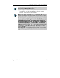
Instructions for IC CS-03 certified equipment 1 The Industry Canada label identifies certified equipment. This certification means that the equipment meets certain telecommunications network protective,operational and safety requirements as prescribed in the appropriate TerminalEquipment Technical R...
Page 9 - Notes for Users in Australia and New Zealand; Modem warning notice for Australia
3 The standard connecting arrangement (telephone jack type) for this equipment isjack type(s): USOC RJ11C. The IC registration number of the modem is shown below. Canada: 1353A-L4AINT Notes for Users in Australia and New Zealand Modem warning notice for Australia Modems connected to the Australian t...
Page 10 - Notes for use of this device in New Zealand
Notes for use of this device in New Zealand ❑ The grant of a Telepermit for a device in no way indicates Telecom acceptanceof responsibility for the correct operation of that device under all operatingconditions. In particular the higher speeds at which this modem is capable ofoperating depend on a ...
Page 12 - General conditions
General conditions As required by PTC 100, please ensure that this office is advised of any changes tothe specifications of these products which might affect compliance with the relevantPTC Specifications. The grant of this Telepermit is specific to the above products with the marketingdescription a...
Page 13 - Description on Laser specification
Description on Laser specification The optical drive such as CD-ROM drive, CD-RW drive, DVD-ROM drive, DVD/CD-RW drive and DVD Multi drive that is used in this computer is equipped withlaser. The classification label with the following sentence is affixed to the surface ofthe drive. CLASS 1 LASER PR...
Page 15 - x v; Table of Contents; Preface
x v Table of Contents Preface Manual contents ............................................................................. xxiiiConventions ..................................................................................... xxiv Abbreviations .........................................................
Page 16 - xvi; Chapter 3 Getting Started
xvi Underside ........................................................................................... 2-7Front with the display open .............................................................. 2-8System indicators ............................................................................ 2-...
Page 17 - xvii
xvii Changing Lifestyle Bay modules ..................................................... 4-3 Removing a module ............................................................................ 4-3Installing a module .............................................................................. 4-4 Using...
Page 18 - xviii; Chapter 5 The Keyboard
xviii Chapter 5 The Keyboard Typewriter keys ................................................................................. 5-1F1 … F12 function keys ..................................................................... 5-2Soft keys: Fn key combinations ..............................................
Page 19 - xix; Chapter 7 HW Setup and Passwords
xix Panel power off ............................................................................... 6-15System Auto Off ............................................................................... 6-15 Chapter 7 HW Setup and Passwords HW Setup ........................................................
Page 20 - x x; Chapter 9 Troubleshooting
x x Chapter 9 Troubleshooting Problem solving process ................................................................... 9-1 Preliminary checklist .......................................................................... 9-1Analyzing the problem .......................................................
Page 21 - xxi; Appendixes
xxi Appendixes Appendix ASpecifications ................................................................................... A-1 Appendix BDisplay Controller and Modes ......................................................... B-1 Appendix CAT Commands ....................................................
Page 22 - xxii
Page 23 - xxiii; Manual contents
xxiii Preface Congratulations on your purchase of the Satellite 2450 series computer. Thispowerful notebook computer provides excellent expansion capability, includingmultimedia devices, and it is designed to provide years of reliable, high-performancecomputing. This manual tells how to set up and b...
Page 24 - x x i v; Conventions; Abbreviations; Enter
x x i v User's Manual Chapter 4, Operating Basics , includes instructions on using the following devices: Touch Pad, Slim Select Bay modules, USB diskette drive, optical media drives,audio/video controls, microphone, modem, wireless communication features, LAN.It also provides tips on care of the co...
Page 25 - xxv; Key operation; Ctrl; Display; ABC; Messages
xxv Key operation Some operations require you to simultaneously use two or more keys. We identifysuch operations by the key top symbols separated by a plus sign ( + ). For example, Ctrl + C means you must hold down Ctrl and at the same time press C . If three keys are used, hold down the first two a...
Page 26 - x x v i
Page 27 - xxvii; General Precautions; Stress injury; Heat injury
xxvii General Precautions TOSHIBA computers are designed to optimize safety, minimize strain and withstandthe rigors of portability. However, certain precautions should be observed to furtherreduce the risk of personal injury or damage to the computer. Be certain to read the general precautions belo...
Page 28 - xxviii; PC card overheating
User's Manual xxviii Central Processing Unit ("CPU") PerformanceDisclaimer CPU Performance in your computer product may vary from specifications under thefollowing conditions: use of certain peripheral products use of battery power instead of AC power use of certain multimedia games or video...
Page 29 - Chapter 1; Introduction; Equipment checklist; Hardware
1-1 I NTRODUCTION Chapter 1 Introduction This chapter provides an equipment checklist, and it identifies the computer’sfeatures, options and accessories. CAUTION: Some of the features described in this manual may not function properly if you use an operating system that was not prein-stalled by TOSH...
Page 30 - Documentation; Features; Processor
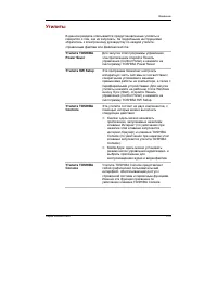
1-2 User's Manual I NTRODUCTION • TOSHIBA Power Saver • TOSHIBA Console • Infrared Device Driver • Online manual ❑ Product Recovery CD-ROM Documentation • Satellite 2450 Portable Personal Computer User's Manual • Microsoft Windows XP manual package • Instruction Manual for Safety & Comfort • End...
Page 31 - Disks
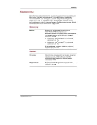
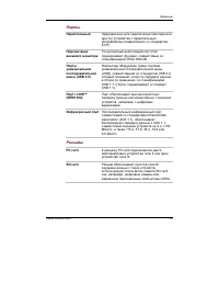
1-3 I NTRODUCTION RTC battery The computer has an internal battery to back up theinternal Real Time Clock (RTC) and calendar. Universal AC adaptor The universal AC adaptor provides power to the systemand recharges the batteries when they are low. It comeswith a detachable power cord. Because it is u...
Page 33 - Keyboard; Pointing device
1-5 I NTRODUCTION Display The computer’s LCD panel supports high-resolution video graphics. The screencan be set at a wide range of viewing angles for maximum comfort and readability. Built-in 15.0" TFT screen, 16 M colors, with one of the followingresolutions:• XGA, 1024 horizontal x 768 vertic...
Page 34 - Slots
1-6 User's Manual I NTRODUCTION Slots PC card The PC card slot accommodates two 5 mm Type II cards orone Type III card. SD card This slot lets you easily transfer data from devices, such asdigital cameras and Personal Digital Assistants, that useSD card flash-memory.You can use memory module in this...
Page 35 - Communications; Slim Select Bay
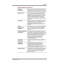
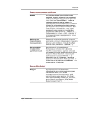
1-7 I NTRODUCTION Features Communications Modem An internal modem provides capability for data and faxcommunication. It supports V.90 (V.92). Refer to Appendix E . The speed of data transfer and fax depends on analog telephone line conditions. It has a modem jack forconnecting to a telephone line. I...
Page 36 - Software; Special features
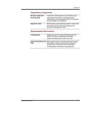
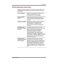
1-8 User's Manual I NTRODUCTION Software Standard Windows XP operating system and TOSHIBA Utilities anddrivers preinstalled on the hard disk. Plug and Play When you connect an external device to the computer,Plug and Play capability enables the system to recognizethe connection and make the necessar...
Page 38 - Utilities
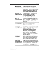
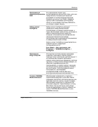
1-10 User's Manual I NTRODUCTION Standby If you have to interrupt your work, you can turn off thepower without exiting from your software. Data is main-tained in the computer’s main memory. When you turn onthe power again, you can continue working right whereyou left off. Utilities This section desc...
Page 39 - Options
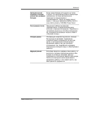
1-11 I NTRODUCTION Options ConfigFree ConfigFree is a suite of utilities to allow easy control ofcommunication device and network connections.ConfigFree also allows you to find communicationprobrems and create profiles for easy switching betweenlocation and communication networks.You can boot Config...
Page 40 - Slim Select Bay options
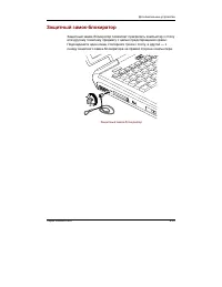
1-12 User's Manual I NTRODUCTION Security lock A slot is available to attach a security cable to the com-puter to deter theft. USB FDD Kit A 3 1/2" diskette drive accommodates 1.44-megabyte or720-kilobyte diskette. It connects to a USB port. (Youcannot format 720-kilobyte diskettes on Windows XP...
Page 41 - Chapter 2; The Grand Tour; Front with the display closed; control buttons; Mode Control; button
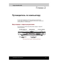
T HE G RAND T OUR 2-1 Chapter 2 The Grand Tour This chapter identifies the various components of your computer. Become familiarwith each component before you operate the computer. Front with the display closed Figure 2-1 shows the computer’s front with its display panel in the closed position. Figur...
Page 42 - Left side; On Off
User's Manual T HE G RAND T OUR 2-2 Display latch This latch secures the LCD panel in its closed position.Slide the latch to open the display. Volume control Use this dial to adjust the volume of the stereo speakersand subwoofer or the stereo headphones. System LEDs let you monitor the status of var...
Page 43 - Cooling vents; Serial Bus; Infrared port
T HE G RAND T OUR 2-3 Left side Cooling vents These vents provide an outlet for air pulled through thecomputer by the fan. CAUTION: Be careful not to block the cooling vents. Also be careful to keep foreign objects out of them. A pin or similar object can damage thecomputer’s circuitry. PC card slot...
Page 44 - Right side; SD card slot
User's Manual T HE G RAND T OUR 2-4 Right side Figure 2-3 shows the computer’s right side. Figure 2-3 The right side of the computer SD card slot SD cards are used in a wide variety of external devices.This slot lets you transfer data from the device to yourcomputer. An indicator on the right side o...
Page 45 - Back side; LAN
T HE G RAND T OUR 2-5 Headphone jack This jack lets you connect digital speakers or a stereoheadphone (16 ohm minimum). When you connect adigital speaker or headphones, the internal speaker isautomatically disabled. Microphone jack A 3.5 mm mini microphone jack enables connection of athree-conductor...
Page 47 - Underside; Under side
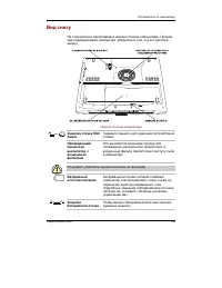
T HE G RAND T OUR 2-7 Underside Figure 2-5 shows the underside of the computer. Make sure the display is closedbefore turning over your computer. Figure 2-5 The underside of the computer Slim Select Bay Slide this latch to free the Slim Select Bay for removal. latch CPU cooling fan This cooling fan ...
Page 48 - Battery release; Front with the display open; Display hinge
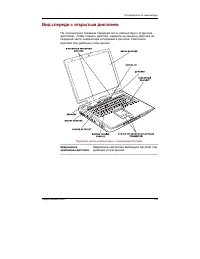
User's Manual T HE G RAND T OUR 2-8 Battery release Slide this latch to release the battery pack for removal. latch Front with the display open Figure 2-6 shows the front of the computer with the display open. To open thedisplay, push the display latch on the front of the display and lift up. Positi...
Page 50 - System indicators
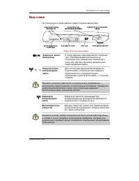
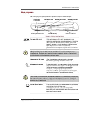
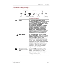
User's Manual T HE G RAND T OUR 2-10 System indicators CD/DVD D IGITAL DC IN 15V P OWER B ATTERY D ISK S LIM S ELECT A UDIO B AY Figure 2-7 System indicators CD/DVD The CD/DVD indicator glows in green when reproducing CD/DVD. This LED does not light usually and is lockednot to light. Press the Mode ...
Page 51 - Keyboard indicators
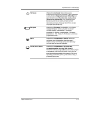
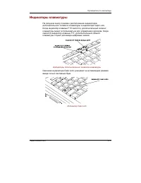
T HE G RAND T OUR 2-11 Disk The Disk indicator glows green when the computer is accessing the built-in hard disk or fixed optical media drive. Slim Select Bay The Slim Select Bay indicator glows green when the computer is accessing a DVD-ROM drive, CD-RW/DVD-ROM drive, DVD-R/-RW drive, DVD Multi dri...
Page 52 - Caps Lock; Numeric mode; USB diskette drive
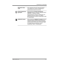
User's Manual T HE G RAND T OUR 2-12 When the CapsLock indicator glows the keyboard is in all-caps mode. Figure 2-9 CapsLock indicator Caps Lock This indicator glows green when the alphabet keys arelocked in uppercase. Arrow mode When the Arrow mode indicator lights green, you can use the keypad ove...
Page 53 - Indicator; Eject button; Slim Select Bay modules
T HE G RAND T OUR 2-13 Slim Select Bay modules Disk-In-Use This indicator lights when the diskette is being accessed. Indicator Diskette slot Insert diskettes in this slot. Eject button When a diskette is fully seated in the drive, the ejectbutton pops out. To remove a diskette, push in the ejectbut...
Page 55 - DVD Multi drive
T HE G RAND T OUR 2-15 DVD Multi drive The full-size DVD Multi drive module lets you run either 12 cm (4.72") or 8 cm (3.15")CD/DVDs without using an adaptor. It reads DVD-ROMs at maximum 8 speed andCD-ROMs at maximum 24 speed. It writes CD-R at up to 16 speed, CD-RW at up to 8speed, DVD-R a...
Page 56 - TOSHIBA Style Bay Bridge Media Adaptor
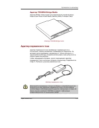
User's Manual T HE G RAND T OUR 2-16 Slim Select Bay HDD adaptor (Black) You can increase your computer’s data storage capacity by installing an optional,integrated, 2 1/2" HDD in the Slim Select Bay. Figure 2-12 The Slim Select Bay HDD adaptor (Black) TOSHIBA Style Bay Bridge Media Adaptor Thre...
Page 57 - Universal AC adaptor
T HE G RAND T OUR 2-17 Universal AC adaptor The universal AC adaptor converts AC power to DC power and reduces the voltagesupplied to the computer. It can automatically adjust to any voltage from 100 to 240volts and to a frequency of either 50 or 60 hertz, enabling you to use the computer inalmost a...
Page 59 - Chapter 3; Getting Started; Setting up your work space
3-1 G ETTING S TARTED Chapter 3 Getting Started This chapter provides basic information to get you started using your computer. Itcovers the following topics: ❑ Setting up your work space — for your health and safety NOTE: Be sure also to read Instruction Manual for Safety & Comfort . This guide...
Page 60 - Placement of the computer
User's Manual G ETTING S TARTED 3 - 2 General conditions In general, if you are comfortable, so is your computer, but read the following tomake sure your work site provides a proper environment. ❑ Make sure there is adequate space around the computer for proper ventilation. ❑ Make sure the AC power ...
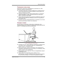
Page 61 - Seating and posture
3-3 G ETTING S TARTED Seating and posture The height of your chair in relation to the computer and keyboard as well as thesupport it gives your body are primary factors in reducing work strain. Refer to thefollowing tips and to figure 3-1. Figure 3-1 Posture and positioning of the computer ❑ Place y...
Page 62 - Lighting
User's Manual G ETTING S TARTED 3 - 4 Lighting Proper lighting can improve legibility of the display and reduce eye strain. ❑ Position the computer so that sunlight or bright indoor lighting does not reflectoff the screen. Use tinted windows, shades or other screen to eliminate sunglare. ❑ Avoid pla...
Page 63 - Connecting the universal AC adaptor; Connecting the AC adaptor
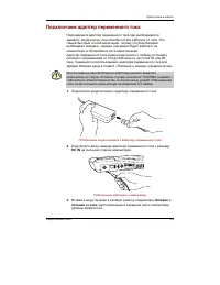
3-5 G ETTING S TARTED Connecting the universal AC adaptor Attach the universal AC adaptor when you need to charge the battery or you wantto operate from AC power. It is also the fastest way to get started, because thebattery pack will need to be charged before you can operate from battery power. The...
Page 64 - Opening the display; Turning on the power
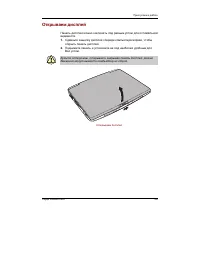
User's Manual G ETTING S TARTED 3 - 6 Opening the display The display panel can be rotated in a wide range of angles for optimal viewing. 1. Slide the display latch on the front of the computer to the right. 2. Lift the panel up and adjust it to the best viewing angle for you. CAUTION: Use reasonabl...
Page 65 - Back; Windows End User License Agreement; Turning off the power; Starting up for the first time
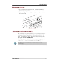
3-7 G ETTING S TARTED 2. Press and hold the computer’s power button for two or three seconds. Figure 3-5 Turning on the power Starting up for the first time When you first turn on the power, the computer’s initial screen is the MicrosoftWindows XP Startup Screen Logo. Follow the on-screen directions...
Page 66 - start; Hibernation mode; Benefits of hibernation
User's Manual G ETTING S TARTED 3 - 8 3. Click start then click Turn Off Computer . From the Turn Off Computer menu select Turn Off . 4. Turn off the power to any peripheral devices. CAUTION: Do not turn the computer or devices back on immediately. Wait a moment to let all capacitors fully discharge...
Page 67 - Starting Hibernation; Hibernate; Automatic Hibernation
3-9 G ETTING S TARTED Starting Hibernation NOTE: You can also enable Hibernation by pressing Fn + F4 . See Chapter 5, Keyboard , for details. To enter Hibernation mode, follow the steps below. 1. Click start . 2. Select Turn Off Computer . 3. Open the Turn Off Computer dialog box. Hibernate is not d...
Page 68 - Standby mode; Benefits of standby; Executing standby; Stand by
User's Manual G ETTING S TARTED 3 - 1 0 CAUTION: Do not turn the computer or devices back on immediately. Wait a moment to let all capacitors fully discharge. Standby mode If you have to interrupt your work, you can turn off the power without exiting fromyour software. Data is maintained in the comp...
Page 69 - Standby limitations; puter; Restarting the computer
3-11 G ETTING S TARTED 2. Close the display panel. This feature must be enabled. Refer to the System Power Mode item in Power Saver Utility discribed in the Control Panel. Open Performance and Maintenance and open TOSHIBA Power Saver . 3. Press the power button. This feature must be enabled. Refer t...
Page 70 - In Touch with
User's Manual G ETTING S TARTED 3 - 1 2 4. Press the power button and hold it down for five seconds. Wait 10 to 15seconds, then turn the power on again by pressing the power button. Restoring the preinstalled softwarefrom the Product Recovery CD-ROM If preinstalled files are damaged, use the Product...
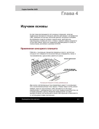
Page 71 - Chapter 4; Pointing devices; Using the Touch Pad
O PERATING B ASICS 4-1 Chapter 4 Operating Basics This chapter gives information on basic operations including using the pointingdevices, USB diskette drive, optical media drives, Sub LCD, audio/video controls,the microphone, the internal modem, wireless communication, LAN, TOSHIBARemote Control and...
Page 72 - Using the USB diskette drive
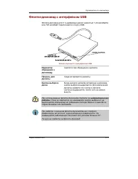
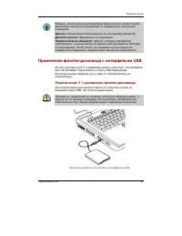
User's Manual O PERATING B ASICS 4-2 Click: Tap the Touch Pad once Double-click: Tap twice Drag and drop: Tap to select the material you want to move. Leave your finger on the Touch Pad after the second tap and move the material. Using the USB diskette drive A 3 1/2" diskette drive connects to t...
Page 73 - Safety Remove Hardware; Removing a module; Changing Slim Select Bay modules
O PERATING B ASICS 4-3 Disconnecting 3 1/2" diskette drive When you have finished using the diskette drive, follow the procedures below todisconnect it: 1. Wait for the indicator light to go out to make sure all diskette activity has stopped. CAUTION: If you disconnect the diskette drive or turn...
Page 74 - Installing a module
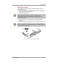
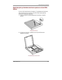
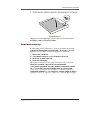
User's Manual O PERATING B ASICS 4-4 CAUTION: Wait for all disk indicators to go out before you turn over the computer and be careful to lay the computer down gently. Shock candamage the HDD or other components. 3. Slide the Slim Select Bay latch to the unlock position. 4. Grasp the DVD-ROM drive an...
Page 75 - Loading discs; Using optical media drives
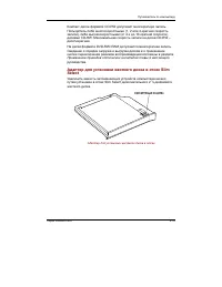
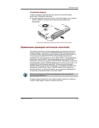
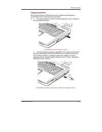
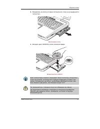
O PERATING B ASICS 4-5 Using optical media drives The text and illustrations in this section refer primarily to the DVD-ROM drive in theSlim Select Bay. However, operation is the same for the CD-RW/DVD-ROM driveand the DVD Multi drive in Slim Select Bay. The full-size drive provides high-performance...
Page 78 - Removing discs
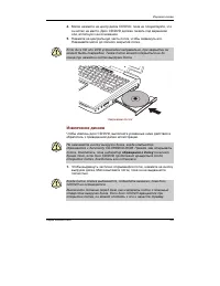
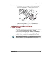
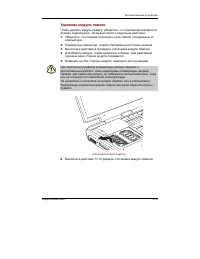
User's Manual O PERATING B ASICS 4-8 Figure 4-9 Closing the DVD-ROM drawer Removing discs To remove the CD/DVD, follow the steps below and refer to figure 4-10. CAUTION: Do not press the eject button while the computer is accessing the Fixed DVD-ROM drive. Wait for the Disk indicator to go out befor...
Page 79 - Before writing or rewriting
O PERATING B ASICS 4-9 Figure 4-10 Removing a CD/DVD 3. Push the center of the drawer to close it. Press gently until it locks into place. Writing CDs on CD-RW/DVD-ROMdrive Depending on the type of drive installed, you may be able to write CDs. The CD-RW/DVD-ROM drive lets you write as well as read ...
Page 80 - When writing or rewriting
User's Manual O PERATING B ASICS 4-10 CD-RW: MITUBISHI CHEMICAL CORPORATION RICOH Co., Ltd. TOSHIBA has confirmed the operation of CD-R and CD-RW media of themanufacturers above. Operation of other media cannot be guaranteed. ❑ CD-RW can generally be rewritten about 1,000 times. However, the actualn...
Page 81 - Important message
O PERATING B ASICS 4-11 • Open the optical media drive. ❑ If the media is poor in quality, dirty or damaged, writing or rewriting errors mayoccur. ❑ Set the computer on a level surface and avoid places subject to vibration suchas airplanes trains, or cars. Do not use an unstable surface such as a st...
Page 82 - Writing CD/DVDs on DVD Multi drive
User's Manual O PERATING B ASICS 4-12 Writing CD/DVDs on DVD Multi drive You can use the DVD Multi drive to write data to either CD-R/-RW or DVD-R/-RW/-RAM discs. The following applications for writing are supplied on CD-ROM:Drag'n Drop CD, licensed by Easy Systems Japan Ltd., and DigiOn Inc., Motio...
Page 83 - Read/write function chart
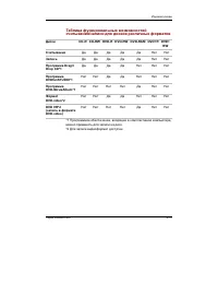
O PERATING B ASICS 4-13 Writing CD/DVDs on DVD Multi drive Read/write function chart Disc type CD-R CD-RW DVD-R DVD-RW DVD-RAM DVD+R DVD+RW Read Write Drag’n Drop CD*1 DVDfunSTUDIO*1 DVD-MovieAlbum*1 DVD-Video*2DVD VR*2 No No No No No No No No No No No No No No No No No No No No No No No No No No (D...
Page 84 - DVD Specifications for Re-recordable Disc for Version 1.1
User's Manual O PERATING B ASICS 4-14 ❑ Based on TOSHIBA's limited compatibility testing, we suggest the followingmanufacturers of CD-R/-RW and DVD-R/-RW/-RAM disc. However, in noevent does TOSHIBA guarantee the operation, quality or performance of anydisc. Disc quality can affect write or rewrite s...
Page 87 - Data Verification
O PERATING B ASICS 4-17 ❑ Do not use the DISC Backup function of Drag'n Drop CD to copy DVD-Videoand DVD-ROM with copyright protection, because the copy will not playcorrectly. ❑ DVD-RAM disc cannot be backed up with the DISC Backup function of Drag'nDrop CD. ❑ You cannot backup a CD-ROM or CD-R/-RW...
Page 89 - Diskettes; Media care
O PERATING B ASICS 4-19 Media care This section provides tips on protecting data stored on your CD/DVDs anddiskettes. Handle your media with care. The following simple precautions will increase thelifetime of your media and protect the data stored on them: CD/DVDs 1. Store your CD/DVDs in the contai...
Page 90 - Modem; Region Select Utility
User's Manual O PERATING B ASICS 4-20 6. Magnetic energy can destroy the data on your diskettes. Keep your diskettes away from speakers, radios, television sets and other sources of magneticfields. Modem This section describes how to connect and disconnect the internal modem to andfrom a telephone j...
Page 91 - Properties menu
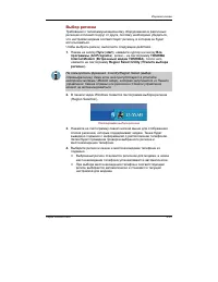
O PERATING B ASICS 4-21 Figure 4-11 The Region Selection icon 3. Click the icon with the primary mouse button to display a list of regions that the modem supports. A sub menu for telephony location information will alsobe displayed. A check will appear next to the currently selected region andteleph...
Page 92 - Setting; AutoRun Mode; Modem Selection; Connecting
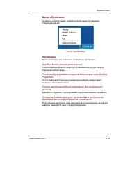
User's Manual O PERATING B ASICS 4-22 Setting You can enable or disable the following settings: AutoRun Mode The Region Select utility starts automatically when you start up the operatingsystem. Open the Dialing Properties dialog box after selecting region. The dialing properties dialog box will be ...
Page 93 - Disconnecting; Wireless LAN; Wireless communications
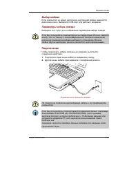
O PERATING B ASICS 4-23 Figure 4-13 Connecting the internal modem CAUTION: Do not pull on the cable or move the computer while the cable is connected. NOTE: If you use a storage device such as a DVD-ROM drive, CD-RW/DVD-ROM drive or HDD connected to a 16-bit PC card, youmight experience the followin...
Page 94 - Security; Worldwide operation
User's Manual O PERATING B ASICS 4-24 ❑ Automatic Transmit Rate Select mechanism in the transmit range of 54, 48, 36,24, 18, 12, 9 and 6Mbit/s. (Revision A) ❑ Automatic Transmit Rate Select mechanism in the transmit range of 11, 5.5, 2and 1Mbit/s. (Revision B) ❑ Automatic Transmit Rate Select mechan...
Page 95 - Radio links; Wireless communication switch; Wireless communication Indicator
O PERATING B ASICS 4-25 Radio links You can easily establish links between two or more devices. The link is maintainedeven if the devices are not within line of sight. Security Two advanced security mechanisms ensure a high level of security: ❑ Authentication prevents access to critical data and mak...
Page 96 - Connecting LAN cable
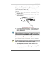
User's Manual O PERATING B ASICS 4-26 LAN The computer has built-in support for Ethernet LAN (10 megabits per second,10BASE-T) and Fast Ethernet LAN (100 megabits per second, 100BASE-Tx).This section describes how to connect/disconnect to a LAN. CAUTION: Do not install or remove an optional memory m...
Page 97 - Disconnecting LAN cable; Cleaning the computer
O PERATING B ASICS 4-27 3. Plug the other end of the cable into a LAN hub connector. Check with yourLAN administrator before connecting to a hub. NOTE: When the computer is exchanging data with the LAN, the LAN Active indicator glows yellow. When the computer is connected to a LAN hub but is not exc...
Page 98 - Moving the computer
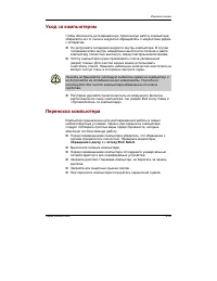
User's Manual O PERATING B ASICS 4-28 Moving the computer The computer is designed for rugged durability. However, a few simple precautionstaken when moving the computer will help ensure trouble-free operation. ❑ Make sure all disk activity has ended before moving the computer. Check the Disk and Sl...
Page 99 - Chapter 5; Typewriter keys; Shift
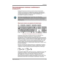
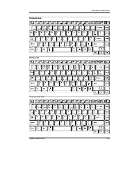
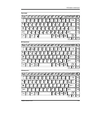
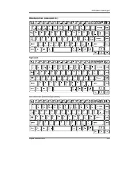
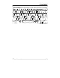
5-1 T HE K EYBOARD Chapter 5 The Keyboard The computer’s keyboard layouts are compatible with a 101/102-key enhancedkeyboard. By pressing some keys in combination, all the 101/102-key keyboardfunctions can be executed on the computer. The number of keys on your keyboard depends on which country/regi...
Page 100 - F1 ... F12 function keys; Soft keys: Fn key combinations; Fn; Emulating keys on enhanced keyboard
User's Manual 5-2 T HE K EYBOARD F1 … F12 function keys The function keys, not to be confused with Fn , are the 12 keys at the top of your keyboard. These keys function differently from other keys. F1 through F12 are called function keys because they execute programmed functions when pressed. Used i...
Page 102 - Hot keys
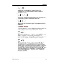
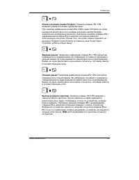
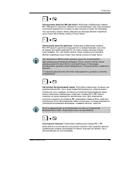
User's Manual 5-4 T HE K EYBOARD Hot keys Hot keys ( Fn + a function or Esc key) let you enable or disable certain features of the computers. Sound mute: Pressing Fn + Esc in a Windows environment turns sound on or off. When you press these hot keys, the current setting will change and bedisplayed a...
Page 105 - Fn Sticky key; Turning on the overlays; Arrow mode; Windows special keys
5-7 T HE K EYBOARD Fn Sticky key You can use the TOSHIBA Accessibility Utility to make the Fn key sticky, that is, you can press it once, release it, and they press an “ F number ” key. To start the TOSHIBA Accessibility Utility, click start , point to All Programs , point to TOSHIBA Utilities and c...
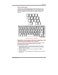
Page 107 - Temporarily changing modes; Generating ASCII characters
5-9 T HE K EYBOARD Temporarily using overlay (overlay off) While using the normal keyboard, you can temporarily use the keypad overlaywithout turning it on: 1. Press and hold down Fn . 2. Check the keyboard indicators. Pressing Fn turns on the most recently used overlay. If the Numeric mode indicato...
Page 109 - Chapter 6; Power conditions
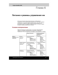
P OWER AND P OWER -U P M ODES 6 - 1 Chapter 6 Power and Power-Up Modes The computer’s power resources include the universal AC adaptor and internalbatteries. This chapter gives details on making the most effective use of theseresources including charging and changing batteries, tips for saving batte...
Page 110 - Power indicators; Power; Battery indicators
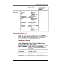
6-2 User's Manual P OWER AND P OWER -U P M ODES Table 6-1 Power conditions continued Power on Power off (no operation) AC Battery • Operates adaptor charge is • LED: Battery off not above low DC IN off connected battery trigger point Battery • Operates charge is • LED: Battery below low flashes oran...
Page 111 - DC IN indicator; Power indicator; Battery types
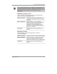
P OWER AND P OWER -U P M ODES 6 - 3 NOTE: If the battery becomes too hot while it is being charged, the charge will stop and the battery indicator will go out. When the battery’stemperature falls to a normal range, charge will resume. This occurswhether the computer’s power is on or off. DC IN indic...
Page 112 - Real Time Clock battery
6-4 User's Manual P OWER AND P OWER -U P M ODES Before you remove the battery pack, set the computer to Hibernation mode or saveyour data and shut down the computer. Do not change the battery pack while theuniversal AC adaptor is connected. CAUTIONS: 1. The battery pack is a lithium ion battery, whi...
Page 113 - Safety precautions; Danger; Care and use of the battery pack
P OWER AND P OWER -U P M ODES 6 - 5 CAUTION: The computer’s RTC battery is a lithium ion battery and should be replaced only by your dealer or by a TOSHIBA servicerepresentative. The battery can explode if not properly replaced, used,handled or disposed of. Dispose of the battery as required by loca...
Page 114 - Warning
6-6 User's Manual P OWER AND P OWER -U P M ODES 4. Never puncture the battery pack with a nail or other sharp object. Never strike it with a hammer or other object. Never step on it. 5. Never try to charge the battery pack in any manner other than that described in the user’s manual. Never connect t...
Page 115 - Caution; Note
P OWER AND P OWER -U P M ODES 6 - 7 Care and use of the battery pack Caution 1. Never continue to use a battery pack after its recharging capacity has become impaired, or after the display of a warning message indicating that the batterypack’s power is exhausted. Continued use of an exhausted or imp...
Page 116 - Charging the batteries; Procedures; Time
6-8 User's Manual P OWER AND P OWER -U P M ODES Charging the batteries When the power in the battery pack becomes low, the Battery indicator flashes orange indicating that only a few minutes of battery power remain. If you continueto use the computer while the Battery indicator flashes, the computer...
Page 117 - Battery charging notice; Monitoring battery capacity
P OWER AND P OWER -U P M ODES 6 - 9 Battery charging notice The battery may not charge right away under the following conditions: ❑ The battery is extremely hot or cold. If the battery is extremely hot, it might notcharge at all. To ensure the battery charges to its full capacity, charge thebattery ...
Page 118 - Maximizing battery operating time
6-10 User's Manual P OWER AND P OWER -U P M ODES 2. With repeated discharges and recharges, the battery’scapacity will gradually decrease. Therefore, an oftenused, older battery will not operate for as long as a newbattery even when both are fully charged. In this case,Power Save Modes window in TOS...
Page 119 - Retaining data with power off
P OWER AND P OWER -U P M ODES 6 - 1 1 Care and use of the battery pack Retaining data with power off When you turn off your computer with fully charged batteries, the batteries retaindata for the following approximate time periods: Battery pack about 6 days (Standby mode)about 30 days (Boot mode) RT...
Page 120 - Replacing the battery pack; Removing the battery pack
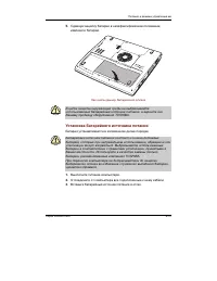
6-12 User's Manual P OWER AND P OWER -U P M ODES Replacing the battery pack When the battery pack reaches the end of its operating life you will need to install anew one. The life of the battery pack is generally about 500 recharges. If the Battery indicator flashes orange shortly after fully rechar...
Page 121 - Installing the battery pack
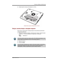
P OWER AND P OWER -U P M ODES 6 - 1 3 Figure 6-1 Releasing the battery cover CAUTION: For environmental reasons, do not throw away a spent battery pack. Please return spent battery packs to your TOSHIBA dealer. Installing the battery pack To install a battery, follow the steps below. CAUTIONS: 1. Th...
Page 122 - Starting the computer by password
6-14 User's Manual P OWER AND P OWER -U P M ODES Figure 6-2 Securing the battery cover Starting the computer by password To start up the computer with the user password, follow these steps: 1. Turn on the power as described in Chapter 3, Getting Started . The following message appears: Password = NO...
Page 123 - Windows utilities; Panel power off; System Auto Off
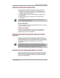
P OWER AND P OWER -U P M ODES 6 - 1 5 Power-up modes The computer has the following power-up modes: ❑ Boot: Computer shuts down without saving data. Always save your workbefore you turn the computer off in boot mode. ❑ Hibernation: Data in memory is saved to the hard disk. ❑ Standby: Data is maintai...
Page 125 - Chapter 7; HW Setup and Passwords; HW Setup; Accessing HW Setup; TOSHIBA HW; HW Setup window; OK; Cancel; Apply
7 - 1 HW S ETUP AND P ASSWORDS Chapter 7 HW Setup and Passwords This chapter explains how to use TOSHIBA HW Setup program to configure yourcomputer and how to set passwords. HW Setup TOSHIBA HW Setup lets you configure settings for Display, Boot Priority,Keyboard, USB, LAN, General, Password, Device...
Page 126 - Power On Display; Boot Priority; Boot Priority Options
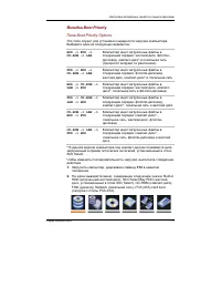
User's Manual 7-2 HW S ETUP AND P ASSWORDS Display This tab lets you customize your computer’s display settings for either the internalLCD screen or for an external monitor. Power On Display Lets you set the display to be used when the computer is booted. Auto-Selected Selects an external monitor if...
Page 128 - Network Boot Protocol
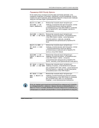
User's Manual 7-4 HW S ETUP AND P ASSWORDS Built-in HDD −> −> −> −> −> PC Card −> −> −> −> −> 2nd HDD HDDs are searched for a boot command in the followingorder: the built-in HDD, the PC card and the HDD installedin the Slim Select Bay. 2nd HDD −> −> −> −> −...
Page 129 - USB; USB KB/Mouse Legacy Emulation; USB-FDD Legacy Emulation
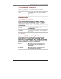
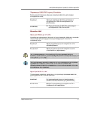
7 - 5 HW S ETUP AND P ASSWORDS USB USB KB/Mouse Legacy Emulation Use this option to enable or disable USB KB/Mouse Legacy Emulation. If youroperating system does not support USB, you can still use a USB mouse andkeyboard by setting the USB KB/Mouse Legacy Emulation item to Enabled . Enabled Enables ...
Page 130 - General; Setup; Password; User Password; Not
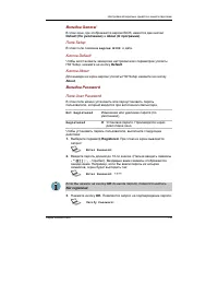
User's Manual 7-6 HW S ETUP AND P ASSWORDS General This window displays the BIOS version and contains two buttons: Default and About . Setup This field displays BIOS Version and date. Default Click Default to return all HW Setup values to the factory settings. About Click About to display the HW Set...
Page 131 - Not Registered
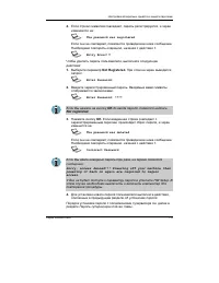
7 - 7 HW S ETUP AND P ASSWORDS 4. If character strings match, the password is registered and the display changes to: The password was registered If they do not match, the following message appears. You must repeat fromstep 1. Entry Error!!! To delete a user password: 1. Select Not Registered to disp...
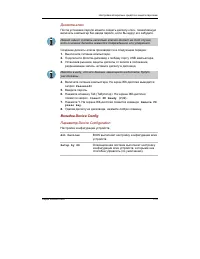
Page 132 - Key FD; Remove FD press key; Device Config; Device Configuration
User's Manual 7-8 HW S ETUP AND P ASSWORDS Key FD After you set a password, you can create a Key FD (diskette). If you forget the userpassword, the Key FD lets you bypass the password function. NOTE: It is a good idea to create more than one Key FD in case a Key FD is damaged or lost. To create a Ke...
Page 133 - Parallel Port Mode; Supervisor password
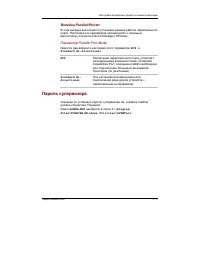
7 - 9 HW S ETUP AND P ASSWORDS Parallel/Printer This tab lets you set the Parallel Port Mode. Use the Windows Device Manager tomake settings for the Parallel port. Parallel Port Mode The options in this tab are ECP and Standard Bi-directional . ECP Sets the port type to Extended Capabilities Port (E...
Page 135 - Chapter 8; Optional Devices; Power devices
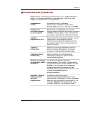
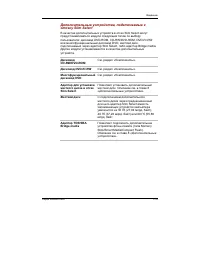
8 - 1 O PTIONAL D EVICES Chapter 8 Optional Devices Optional devices can expand the computer’s capabilities and its versatility. Thischapter describes connection or installation of the following devices, which areavailable from your TOSHIBA dealer: Cards/memory ❑ PC cards ❑ SD cards ❑ Memory expansi...
Page 136 - PC cards; Inserting a PC card
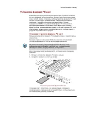
User's Manual 8-2 O PTIONAL D EVICES PC cards The computer is equipped with a PC card expansion slot that can accommodate two5 mm Type II cards. Any PC card that meets industry standards (manufactured byTOSHIBA or other vendor) can be installed. The slot supports 16-bit PC cards,including PC card 16...
Page 137 - Removing a PC card
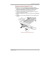
8 - 3 O PTIONAL D EVICES Removing a PC card To remove the PC card, follow the steps below. 1. Click the Safety Remove Hardware icon on the Task Bar. 2. Click PC card . 3. Press the PC card eject button to extend it. 4. Press the extended eject button to pop the card out slightly. 5. Pinch the PC car...
Page 138 - SD cards; Inserting an SD card
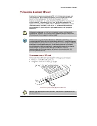
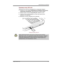
User's Manual 8-4 O PTIONAL D EVICES SD cards The computer is equipped with an SD card slot that can accommodate SecureDigital flash memory cards with various memory capacities. SD cards let you easilytransfer data from devices, such as digital cameras and Personal Digital Assistants,that use SD car...
Page 139 - Removing an SD card; SD card care
8 - 5 O PTIONAL D EVICES SD cards Removing an SD card To remove an SD card, follow the steps below. 1. Click the Safety Remove Hardware icon on the Task Bar. 2. Point to SD card and click. 3. Push in the card and release it to pop the card out slightly. 4. Grasp the card and remove it. Figure 8-4 Re...
Page 140 - Memory expansion; Installing memory module
User's Manual 8-6 O PTIONAL D EVICES 5. Do not twist or bend SD cards. 6. Do not expose SD cards to liquids or store in humid areas or in lay media closeto containers of liquid. 7. After using an SD card, return it to its case. 8. Do not touch the metal part or expose it to liquids or let it get dir...
Page 145 - System Properties; Removing memory module
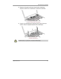
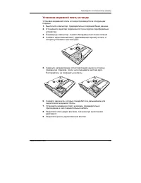
8 - 1 1 O PTIONAL D EVICES 12. Insert the tabs of the keyboard into the slits of the computer case and seat the keyboard at the original position. Fix it with three screws removed in 6. CAUTIONS: 1. Be sure to use all screws that were removed in 6 and do not leave foreign matters such as adhesive ta...
Page 147 - Before installing; Inserting; TOSHIBA Style Bay Bridge media adaptor
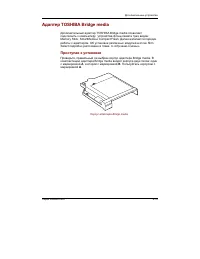
8 - 1 3 O PTIONAL D EVICES Before installing Make sure you have the correct Bridge media adaptor case. Two cases come withthe Bridge media adaptor: one marked A and one marked B . The case for the Satellite Pro M10 is marked with a B . NOTE: Case B is also used with the Satellite 2450 computer. Case...
Page 148 - Removing
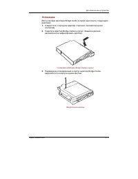
User's Manual 8-14 O PTIONAL D EVICES 3. Turn the Bridge media adaptor with case upside down and secure the case to the adaptor with one screw. Figure 8-16 Secureing a screw Removing To remove the Bridge media adaptor from the case, follow the steps below. 1. Turn the Bridge media adaptor with case ...
Page 149 - SmartMedia; Write protection
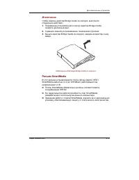
8 - 1 5 O PTIONAL D EVICES SmartMedia This slot accommodates 3.3 V SmartMedia (RAM) from 2 MB to 128 MB. ❑ You cannot use SmartMedia that does not conform to SSFDC specifications. ❑ Operation of SmartMedia developed after the computer was manufactured isnot guaranteed. ❑ After you finish using Smart...
Page 150 - Eject
User's Manual 8-16 O PTIONAL D EVICES Figure 8-18 Inserting a SmartMedia Removing CAUTION: Do not remove a SmartMedia card while data is being written or read. Data could be destroyed. Wait for SmartMedia indicator on the left side of the SmartMedia slot to go out. 1. Right click (right button of th...
Page 151 - Memory Stick; Removing a Memory Stick
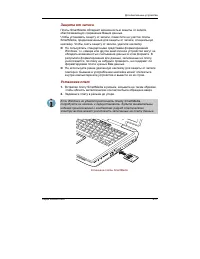
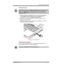
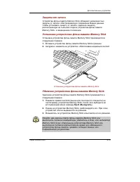
8 - 1 7 O PTIONAL D EVICES Memory Stick This slot accommodates Memory Stick from 16MB to 128MB. NOTE: The slot does not support Magic Gate functions. Write protection Memory Stick can be write protected to safeguard your data. To write-protect aMemory Stick, slide the lock on the back of the Memory ...
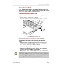
Page 152 - Compact Flash; Installing a Compact Flash module; Removing a Compact Flash memory module
User's Manual 8-18 O PTIONAL D EVICES CAUTION: Make sure the Memory Stick indicator is out before you remove the Memory Stick or turn off the computer’s power. If you removethe Memory Stick or turn off the power while the computer is accessingthe Memory Stick, you may lose data or damage the Memory ...
Page 153 - Bridge media care
8 - 1 9 O PTIONAL D EVICES CAUTION: Make sure the Compact Flash indicator is out before you remove the Compact Flash or turn off the computer’s power. If youremove the Compact Flash or turn off the power while the computer isaccessing the Compact Flash you may lose data or damage the CompactFlash. B...
Page 155 - TV; External monitor
8 - 2 1 O PTIONAL D EVICES TV 3. Close the lid and slide the lock to the lock position. Figure 8-24 Closing the lid For details on installing the Slim Select Bay HDD adaptor in the Slim Select Bay,refer to Chapter 4, Operating Basics . External monitor An external analog monitor can be connected to ...
Page 156 - Using the TV button; Changing the resolution; Display properties
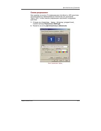
User's Manual 8-22 O PTIONAL D EVICES TV You can connect a television set to the TV out jack on the computer. Follow thesteps below. Using the TV button 1. Connect the TV adaptor cable’s S-Video plug to the TV out jack on the computer. 2. Connect the TV adaptor cable’s MINI DIN 4Pin connector S-Vide...
Page 157 - Adapter
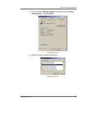
8 - 2 3 O PTIONAL D EVICES Figure 8-25 Display properties (3) Select the Adapter tab, then select List all modes . Figure 8-26 The Adapter window (4) Select a resolution from the menu. i.LINK (IEEE1394)
Page 158 - Precautions
User's Manual 8-24 O PTIONAL D EVICES Figure 8-27 Resolution menu i.LINK (IEEE1394) i.LINK (IEEE1394) is used for high-speed data transfer for a range of compatibledevices such as ❑ Digital video cameras ❑ Hard disk drives ❑ MO drives ❑ CD-RW drives NOTE: i.LINK uses a four-pin connector, which does...
Page 159 - Security lock
8 - 2 5 O PTIONAL D EVICES ❑ If you are transferring data through an IEEE1394 hub, do not connect ordisconnect other devices from the hub during data transfer. There is a likeli-hood that data will be damaged. Connect all devices to the hub before you turnon the computer’s power. ❑ You may not use a...
Page 161 - Chapter 9; Troubleshooting; Problem solving process; PrtSc; Preliminary checklist
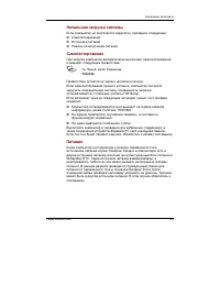
9-1 T ROUBLESHOOTING Chapter 9 Troubleshooting TOSHIBA designed the computer for durability. However, should problems occur,following the procedures in this chapter can help to determine the cause. All readers should become familiar with this chapter. Knowing what might go wrongcan help prevent prob...
Page 162 - Analyzing the problem
User's Manual T ROUBLESHOOTING 9-2 ❑ Check that your diskette or CD/DVD-ROM is correctly inserted and that thediskette’s write protect tab is correctly set. Make notes of your observations and keep them in a permanent error log. This willhelp you describe your problems to your dealer. If a problem r...
Page 163 - Hardware and system checklist
9-3 T ROUBLESHOOTING Hardware If you cannot find a software problem, check your hard-ware. First run through the items in the preliminarychecklist above. If you still cannot correct the problem, tryto identify the source. The next section provides checklistsfor individual components and peripherals....
Page 164 - Self test
User's Manual T ROUBLESHOOTING 9-4 Self test When the computer starts up, the self test will be run automatically, and thefollowing will be displayed: In Touch with TomorrowTOSHIBA This message remains on the screen for a few seconds. If the self test is successful, the computer tries to load the op...
Page 165 - Overheating power down
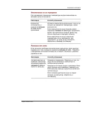
9-5 T ROUBLESHOOTING Overheating power down If the computer’s internal temperature becomes too high, the computer will automati-cally shut down. Problem Procedure Computer shuts down Leave the computer off until the computer and DC IN indicator reaches room temperature, then turn it back on. blinks ...
Page 166 - Problem
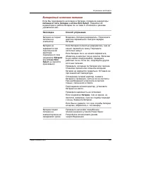
User's Manual T ROUBLESHOOTING 9-6 Battery If you suspect a problem with the battery, check the DC IN indicator as well as the Battery and Slim Select Bay indicators. For information on indicators and battery operation see Chapter 6, Power and Power-Up Modes . Problem Procedure Battery doesn’t The b...
Page 167 - LCD panel
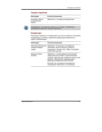
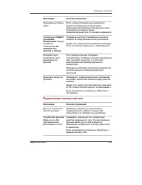
9-7 T ROUBLESHOOTING Hardware and system checklist Password Problem Procedure Cannot enter Contact your dealer. or forgot password NOTE: For information on setting a password, refer to Chapter 7, HW Setup and Passwords . Keyboard Keyboard problems can be caused by your setup configuration. For more ...
Page 168 - Hard disk drive
User's Manual T ROUBLESHOOTING 9-8 Markings appear on They might have come from contact with the the LCD. keyboard, Touch Pad. Try wiping the LCD gentlywith a clean dry cloth. If markings remain, useLCD cleaner. Be sure to let the LCD dry beforeclosing it. Problems above Refer to your software’s doc...
Page 175 - Diskette drive; SD card
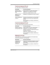
9-15 T ROUBLESHOOTING • Do not run or start other software during writing. • Do not jar the computer during writing.• Do not connect/ disconnect external devices or install/remove internal cards during writing. If problems persist, contact your dealer. Diskette drive For more information, refer to C...
Page 176 - PC card
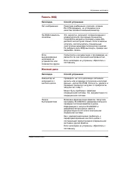
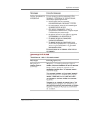
User's Manual T ROUBLESHOOTING 9-16 You cannot write Make sure the card is not write protected. to an SD card You cannot read Make sure the target file is on the SD a file Card inserted in the slot. If problems persist, contact your dealer. PC card Refer also to Chapter 8, Optional Devices . Problem...
Page 177 - Touch Pad
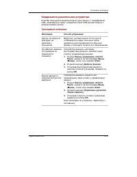
9-17 T ROUBLESHOOTING Pointing device If you are using a USB mouse, also refer to the USB section in this chapter and to your mouse documentation. Touch Pad Problem Procedure On-screen pointer The system might be busy. If the pointer is does not respond to shaped as an hourglass, wait for it to resu...
Page 178 - USB mouse
User's Manual T ROUBLESHOOTING 9-18 USB mouse Problem Procedure On-screen pointer The system might be busy. If the pointer is does not respond to shaped as an hourglass, wait for it to resume mouse operation its normal shape and try again to move it. Make sure the mouse is properly connected tothe U...
Page 179 - MEM1 ERROR
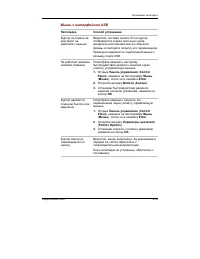
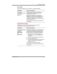
9-19 T ROUBLESHOOTING Hardware and system checklist USB Refer also to your USB device’s documentation. Problem Procedure USB device does Check for a firm cable connection between the not work USB ports on the computer and the USB device. Make sure the USB device drivers are properlyinstalled. Refer ...
Page 180 - Sound system
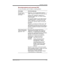
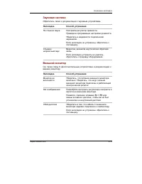
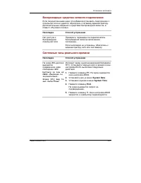
User's Manual T ROUBLESHOOTING 9-20 Sound system Refer also to documentation for your audio devices. Problem Procedure No sound is heard Adjust the volume control dial. Check the software volume settings. Make sure the headphone connection is secure.If problems persist, contact your dealer. Annoying...
Page 181 - M o d e m
9-21 T ROUBLESHOOTING Display error occurs Check that the cable connecting the externalmonitor to the computer is attached firmly. If problems persist, contact your dealer. i.LINK (IEEE1394) Problem Procedure i.LINK device does Make sure the cable is securely connected to not function the computer a...
Page 182 - CONNECT
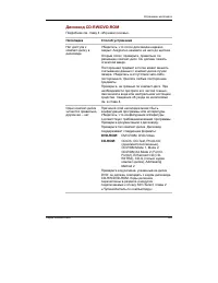
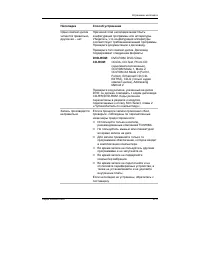
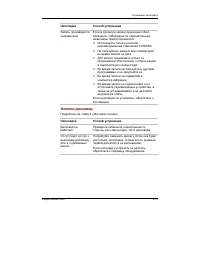
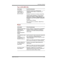
User's Manual T ROUBLESHOOTING 9-22 You can also use the ATX command. Refer to theonline help files for Appendix C, AT Commands . You place a call, Make sure the settings are correct in your but a connection communications application. can’t be made After making a call Make sure the tone or pulse se...
Page 184 - Bluetooth; Real Time Clock
User's Manual T ROUBLESHOOTING 9-24 Bluetooth For more information on wireless communication, refer to Chapter 4, Operating Basics . Problem Procedure Cannot access Make sure the computer’s wireless communica- Bluetooth device tion switch is set to on. Make sure the Bluetooth Manager is running andt...
Page 185 - Before you call; Outside of Europe; Canada; China; TOSHIBA support
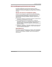
9-25 T ROUBLESHOOTING TOSHIBA support If you require any additional help using your computer or if you are havingproblems operating the computer, you may need to contact TOSHIBA for additionaltechnical assistance. Before you call Some problems you experience may be related to software or the operati...
Page 186 - In Europe
User's Manual T ROUBLESHOOTING 9-26 United States of America TOSHIBA America Information Systems,Inc. 9740 Irvine Boulevard Irvine, California 92618 USA In Europe Germany & Austria TOSHIBA Europe (I.E.) GmbH Geschäftsbereich, Deutschland-Österreich Hammfelddamm 8, D-41460 Neuss, Germany France T...
Page 187 - Appendix A; Specifications; Environmental Requirements
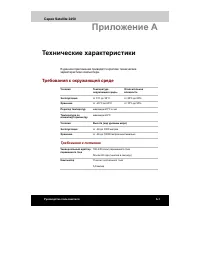
A PPENDIX A A - 1 Appendix A Specifications This appendix summarizes the computer’s technical specifications. Environmental Requirements Ambient Relative Conditions temperature humidity Operating 5°C (41°F) to 35°C (95°F) 20% to 80% Non-operating -20°C (-4°F) to 65°C (149°F) 10% to 95% Thermal Gradi...
Page 188 - Communication specifications
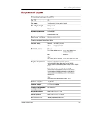
A PPENDIX A A-2 User's Manual Communication specifications Communication Data: Full duplex system Fax: Half duplex Communication Data protocol ITU-T-Rec V.21/V.22/V.22bis/V.32 (Former CCITT) /V.32bis/V.34/V.90 Bell 103/212A Fax ITU-T-Rec V.17/V.29/V.27ter (Former CCITT) /V.21 ch2 Communication Data ...
Page 189 - Display controller
B-1 A PPENDIX B Appendix B Display Controller andModes Display controller The display controller interprets software commands into hardware commands thatturn particular pels on or off. The controller is an advanced Video Graphics Array (VGA) that provides ExtendedGraphics Array (XGA) and Super Exten...
Page 190 - Video modes
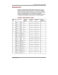
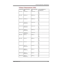
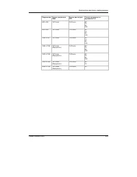
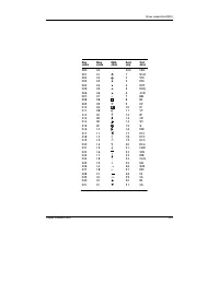
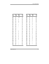
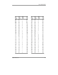
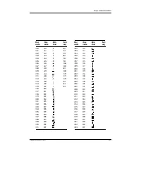
User's Manual B-2 A PPENDIX B Video modes The computer supports video modes defined in the tables below. If your applicationoffers a selection of mode numbers that do not match the numbers on the table,select a mode based on mode type, resolution, character matrix, number of colorsand refresh rates....
Page 199 - Appendix C; ATXn; Repeat last command
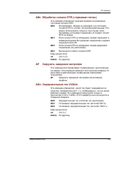
C - 1 A PPENDIX C Appendix C AT Commands In most cases, you will not need to type AT commands manually. However,there might be some occasions when you will need to do so. This chapter describes AT commands for data mode. Fax and voice commandsare taken care of by application software. The format for...
Page 200 - Answer command; Dn
User's Manual C-2 A PPENDIX C A Answer command This command instructs the modem to go off-hook and answer anincoming call. Bn Communication standard setting This command determines the communication standard CCITT or Bell. B0 Selects CCITT V.22 mode when the modem is at 1200 bps. B1 Selects Bell 212...
Page 201 - Echo command
C - 3 A PPENDIX C ; Return to command mode. Causes the modem to return tocommand mode after dialing a number, without disconnectingthe call. S=n Dial a telephone number previously stored using the &Zn=Xcommand (See &Zn=X command for more information). Therange is 0-3. En Echo command This co...
Page 202 - Ln; Mn Monitor speaker mode; Nn
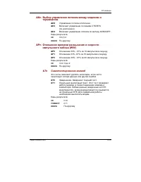
User's Manual C-4 A PPENDIX C Ln Monitor speaker volume This command sets speaker volume to low, medium, or high. L0 Low volume. L1 Low volume. (Same as L0 ) L2 Medium volume (default). L3 High volume. Result Codes: OK n=0,1,2,3 ERROR Otherwise Mn Monitor speaker mode This command turns the speaker ...
Page 203 - On
C - 5 A PPENDIX C Result Codes: OK n=0,1 ERROR Otherwise On Return on-line to data mode O0 Instructs the modem to exit on-line command mode and returnto data mode (see AT escape sequence, +++). O1 This command issues a retrain before returning to on-line datamode. O3 This command issues a rate reneg...
Page 204 - Select tone dialing; Xn
User's Manual C-6 A PPENDIX C T Select tone dialing This command instructs the modem to send DTMF tones while dialing.Dialed digits are tone dialed until a P command or dial modifier isreceived. This is the default setting. Vn DCE response format This command controls whether result codes (including...
Page 205 - Dial tone detect; Zn
C - 7 A PPENDIX C X5 Enable Enable OK, RING, NO CARRIER, ERROR, NODIALTONE, BUSY, CONNECT <RATE>, RRING, NO BONGTONE, DELAYED, BLACKLISTED, REORDER, WARBLE, CALL WAITING DETECTED Dial tone detect Disabled: The modem dials a call regardless of whether it detects adial tone. Enabled: The modem d...
Page 206 - Load factory settings
User's Manual C-8 A PPENDIX C &C1 DCD turns on when the remote modem’s carrier signal isdetected, and off when the carrier signal is not detected(default). Result Codes: OK n=0,1 ERROR Otherwise &Dn DTR control This command interprets how the modem responds to the state of theDTR signal and ...
Page 207 - &Kn Local flow control selection
C - 9 A PPENDIX C &Gn V.22bis guard tone control This command determines which guard tone, if any, to transmit whiletransmitting in the high band (answer mode). This command is onlyused in V.22 and V.22bis mode. This option is not used in NorthAmerica and is for international use only. &G0 G...
Page 208 - & V Display Current Configuration; Store telephone number
User's Manual C-10 A PPENDIX C &T0 Abort. Stops any test in progress. &T1 Local analog loop. This test verifies modem operation, as wellas the connection between the modem and computer. Anydata entered at the local DTE is modulated, then demodulated,and returned to the local DTE. To work pro...
Page 209 - \Nn Error control mode selection; \Qn Local flow control selection
C - 1 1 A PPENDIX C \Nn Error control mode selection This command determines the type of error control used by the modemwhen sending or receiving data. \N0 Buffer mode. No error control. \N1 Direct mode. \N2 MNP or disconnect mode. The modem attempts to connectusing MNP2-4 error control procedures. ...
Page 210 - \Vn Protocol result code; % B View numbers in blacklist
User's Manual C-12 A PPENDIX C \Vn Protocol result code \V0 Disable protocol result code appended to DCE speed. \V1 Enable protocol result code appended to DCE speed (default). Result Codes: OK n=0,1 ERROR Otherwise % B View numbers in blacklist If blacklisting is in effect, this command displays th...
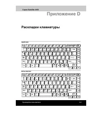
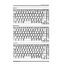
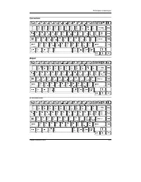
Page 211 - Appendix D
D-1 A PPENDIX D Appendix D S-registers S-registers contain the settings that determine how a number of functions of theinternal modem operate. For example, how many times to let the telephone ringbefore the modem answers and how long to wait before it hangs up if a connec-tion fails. You can also cu...
Page 212 - Auto answer ring number; Ring counter
User's Manual D-2 A PPENDIX D S0 Auto answer ring number This register determines the number of rings the modem will countbefore automatically answering a call. Enter 0 (zero) if you do not wantthe modem to automatically answer at all. When disabled, the modemcan only answer with an ATA command. Ran...
Page 213 - Response formatting character (user defined); Command line editing character (user defined); Wait before dialing
D-3 A PPENDIX D S4 Response formatting character (user defined) This register determines the ASCII value used as the line feed charac-ter. The modem uses a line feed character in command mode when itresponds to the computer. Range: 0-127, ASCII decimal Default: 10 (line feed) Units: ASCII S5 Command...
Page 214 - Connection completion time-out; Comma pause time; S11 DTMF dialing speed
User's Manual D-4 A PPENDIX D S7 Connection completion time-out This register sets the time, in seconds, that the modem must waitbefore hanging up because carrier is not detected. The timer is startedwhen the modem finishes dialing (originate), or goes off-hook (an-swer). In originate mode, the time...
Page 215 - S37 Dial line rate
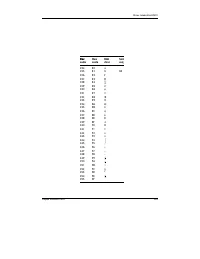
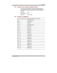
D-5 A PPENDIX D S37 Dial line rate S37 = 0 (default) maximum modem speed S37 = 1 reserved S37 = 2 1200/75 bps S37 = 3 300 bps S37 = 4 reserved S37 = 5 1200 bps S37 = 6 2400 bps S37 = 7 4800 bps S37 = 8 7200 bps S37 = 9 9600 bps S37 = 10 12000 bps S37 = 11 14400 bps S37 = 12 16800 bps S37 = 13 19200 ...
Page 216 - AT command set result codes; The result code summary
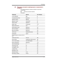
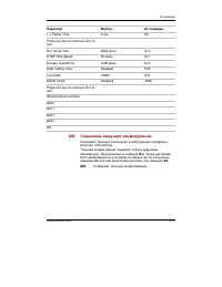
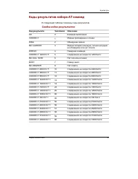
User's Manual D-6 A PPENDIX D AT command set result codes The following table shows the result codes. The result code summary Result Code Numeric Description OK 0 Command executed CONNECT 1 Modem connected to line RING 2 A ring signal has been detected NO CARRIER 3 Modem lost carrier signal, or does...
Page 217 - Result Code
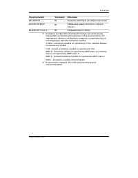
D-7 A PPENDIX D Result Code Numeric Description DELAYED* 2 88 Delay is in effect for the dialednumber BLACKLISTED* 2 89 Dialed number is blacklisted BLACKLIST FULL* 2 90 Blacklist is full *1: EC only appears when the Extended Result Codes configuration option isenabled. EC is replaced by one of the ...
Page 219 - Appendix E; Function
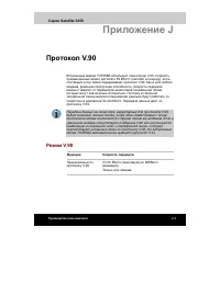
E-1 A PPENDIX E Appendix E V.90 The TOSHIBA internal modem uses V.90 technology. The modem is capable ofdownstream speeds of 56Kbps (kilobits per second) when connected to an Internetservice provider that supports V.90. As with any modem, the actual throughput(speed of data transfer) depends on anal...
Page 221 - AT Command
E-3 A PPENDIX E * EC stands for the Error Control method, which appears only when the extended result codes configuration option is enabled. EC is replaced by one of thefollowing symbols, depending on the error control method used. V42bis V.42 error control and V.42bis data compression V42 V.42 erro...
Page 223 - Appendix F; Internal Modem Guide; Installing the internal modem; Installing the modem board and jack
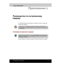
F-1 A PPENDIX F Appendix F Internal Modem Guide This appendix describes how to install and the remove the internal modem. CAUTION: Do not disassemble the computer beyond the steps described in this instruction or touch any components not specifically described. Installing the internal modem NOTE: Th...
Page 224 - Removing the internal modem
F-2 User's Manual A PPENDIX F 5. Pull the guide (plastic tab) toward the direction shown by arrow, then lift the HDD. Be careful not to damage the connector. 6. Remove two screws, which you use later to secure the modem board. 7. Connect the modem board cable and seat the modem board. 8. Secure the ...
Page 225 - Appendix G; Card Specifications; Radio Characteristics
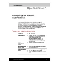
G-1 A PPENDIX G Appendix G Wireless LAN Card Specifications Form Factor - Mini PCI TypeIII Capability - EEE 802.11 Standard for Wireless LANS (DSSS)Wi-Fi (Wireless Fidelity) certified by the Wireless EthernetCompatibility Alliance (WECA) Network Operating - Microsoft Windows® Networking System Media...
Page 226 - Supported Frequency Sub-bands
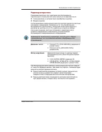
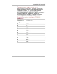
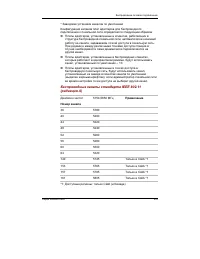
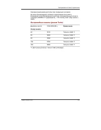
G-2 User's Manual A PPENDIX G Modulation Technique Direct Sequence Spread Spectrum - CCK, DQPSK, DBPSK (Revision B) - OFDM-BPSK, OFDM-QPSK, OFDM-16QAM, OFDM-64QAM (Revision A, Turbo Mode) The range of the wireless signal is related to the Transmit Rate of the wirelesscommunication. Communications at...
Page 229 - Appendix H
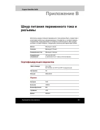
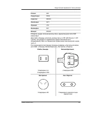
H-1 A PPENDIX H Appendix H AC Power Cord andConnectors The power cord’s AC input plug must be compatible with the various internationalAC power outlets and the cord must meet the standards for the country/region inwhich it is used. All cords must meet the following specifications: Length: Minimum 2 ...
Page 230 - USA and Canada; BS approved
H-2 User's Manual A PPENDIX H The following illustrations show the plug shapes for the U.S.A. and Canada, theUnited Kingdom, Australia and Europe. USA and Canada United Kingdom Australia Europe BS approved UL approvedCSA approved AS approved Approved by theappropriate agency
Page 231 - Appendix I; Parts Numbers
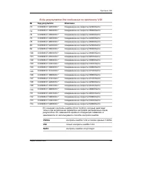
A PPENDIX I I -1 Appendix I Parts Numbers The computer configuration and parts numbers, printed on a label on the bottom ofthe computer, indicate the CPU, LCD, memory, HDD, Slim Select Bay modulesand communication devices.
Page 232 - Configurations
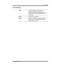
User's Manual I-2 A PPENDIX I Configurations The following table shows the computer configuration indicated on a label. Shaded areas indicate abbreviations used on thelabel. The explanations are to the left of the shading. Abbreviations are not limited to those in this chart. They may changewithout ...
Page 233 - Glossary; AGP
Glossary-1 G LOSSARY Glossary The terms in this glossary cover topics related to this manual. Alternate naming is included for reference. Abbreviations AC: alternating current AGP : accelerated graphics port ANSI: American National Standards Institute APM: advanced power manager ASCII: American Stan...
Page 234 - async; Adaptor
Glossary-2 G LOSSARY analog signal: A signal whose characteristics such as amplitude andfrequency vary in proportion to (are ananalog of) the value to be transmitted.Voice communications are analogsignals. ANSI: American National Standards Institute. An organization establishedto adopt and define st...
Page 235 - cache memory
Glossary-3 G LOSSARY B backup: A duplicate copy of files kept as a spare in case the original isdestroyed. batch file: A file that can be executed from the system prompt containing asequence of operating system com-mands or executable files. binary: The base two number system composed of zeros and o...
Page 236 - capacity
Glossary-4 G LOSSARY capacity: The amount of data that can be stored on a magnetic storagedevice such as a diskette (floppy disk)or hard disk. It is usually described interms of kilobytes (KB), where one KB= 1024 bytes and megabytes (MB),where one MB = 1024 KB. card: Synonym for board . See board. C...
Page 237 - dielete
Glossary-5 G LOSSARY components: Elements or parts (of a system) which make up the whole(system). computer program: A set of instruc- tions written for a computer thatenable it to achieve a desired result. computer system: A combination of hardware, software, firmware, andperipheral components assem...
Page 238 - device driver
Glossary-6 G LOSSARY device driver: A program that controls communication between a specificperipheral device and the computer.The CONFIG.SYS file contains devicedrivers that MS-DOS loads when youturn the computer on. dialog box: A window that accepts user input to make system settings orrecord othe...
Page 239 - Extended Capability Port:
Glossary-7 G LOSSARY escape guard time: A time before and after an escape code is sent to themodem which distinguishes betweenescapes that are part of the transmitteddata, and escapes that are intended asa command to the modem. execute: To interpret and execute an instruction. Extended Capability Po...
Page 240 - hardware
Glossary-8 G LOSSARY hardware: The physical electronic and mechanical components of acomputer system: typically, thecomputer itself, external disk drives,etc. See also software and firmware. hertz: A unit of wave frequency that equals one cycle per second. hexadecimal: The base 16 numbering system c...
Page 241 - menu
Glossary-9 G LOSSARY Liquid Crystal Display (LCD): Liquid crystal sealed between two sheets ofglass coated with transparent con-ducting material. The viewing-sidecoating is etched into characterforming segments with leads thatextend to the edge of the glass.Applying a voltage between the glasssheets...
Page 242 - numeric keypad overlay:; microprocessor
Glossary-10 G LOSSARY N non-system disk: A formatted diskette (floppy disk) you can use to storeprograms and data but you cannot useto start the computer. See system disk. nonvolatile memory: Memory, usually read-only (ROM), that is capable ofpermanently storing information.Turning the computer’s po...
Page 243 - peripheral component interconnect:; prompt
Glossary-11 G LOSSARY output: The results of a computer operation. Output commonly indi-cates data 1) printed on paper, 2)displayed at a terminal, 3) sentthrough the serial port of internalmodem, or 4) stored on some mag-netic media. P parallel interface: Refers to a type of information exchange tha...
Page 244 - Radio frequency interference (RFI) shield
Glossary-12 G LOSSARY ROM: Read Only Memory : A nonvolatile memory chip manufac-tured to contain information thatcontrols the computer’s basicoperation. You cannot access orchange information stored in ROM. S SCSI: Small Computer System Interface is an industry standardinterface for connection of a ...
Page 245 - write protection; Universal Serial Bus:
Glossary-13 G LOSSARY software: The set of programs, procedures and related documentationassociated with a computer system.Specifically refers to computerprograms that direct and control thecomputer system’s activities. See also hardware. stop bit: One or more bits of a byte that follow the transmit...
Page 247 - Index
Index Index-1 I NDEX Index C Cache memory 1-2CD-RW/DVD-ROM drive 1-4, 1-12 location 2-4problems 9-10using 4-5view 2-14writing CDs 4-9 Cleaning the computer 4-27Compact Flash, See Bridge media Cooling (heat dispersal) 1-9 location of vents 2-2, 2-5settings 4-28 CPU, See Processor D Diskette drive 1-3...


 Toshiba Equium A100 (PSAA4)
User Manual
Toshiba Equium A100 (PSAA4)
User Manual
 Toshiba Portege Z830
User Manual
Toshiba Portege Z830
User Manual
 Toshiba Qosmio G30
User Manual
Toshiba Qosmio G30
User Manual
 Toshiba Qosmio G30 HD-DVD
User Manual
Toshiba Qosmio G30 HD-DVD
User Manual
 Toshiba Qosmio X300
User Manual
Toshiba Qosmio X300
User Manual
 Toshiba Satellite 1950
User Manual
Toshiba Satellite 1950
User Manual
 Toshiba Satellite 5200
User Manual
Toshiba Satellite 5200
User Manual
 Toshiba Satellite A10
User Manual
Toshiba Satellite A10
User Manual
 Toshiba Satellite A100
User Manual
Toshiba Satellite A100
User Manual
 Toshiba Satellite A20
User Manual
Toshiba Satellite A20
User Manual
 Toshiba Satellite A200
User Manual
Toshiba Satellite A200
User Manual
 Toshiba Satellite A210
User Manual
Toshiba Satellite A210
User Manual
 Toshiba Satellite A350(D)
User Manual
Toshiba Satellite A350(D)
User Manual
 Toshiba Satellite A40
User Manual
Toshiba Satellite A40
User Manual
 Toshiba Satellite A50
User Manual
Toshiba Satellite A50
User Manual
 Toshiba Satellite A500(D)
User Manual
Toshiba Satellite A500(D)
User Manual
 Toshiba Satellite A60
User Manual
Toshiba Satellite A60
User Manual