Page 2 - WARNING; Introduction
It is a violation of California Public Resource CodeSection 4442 or 4443 to use or operate the engine onany forest-covered, brush-covered, or grass-coveredland unless the engine is equipped with a sparkarrester, as defined in Section 4442, maintained ineffective working order or the engine is constr...
Page 3 - General Safety
Contents Safety ....................................................................... 3 General Safety ................................................... 3Slope Indicator ................................................... 4Safety and Instructional Decals .......................... 5 Product Over...
Page 4 - Slope Indicator
Slope Indicator g011841 Figure 3 1. The maximum slope you can safely operate the machine on is 10° . Use the slope indicator to determine the degree of slope of hills before operating. Do not operate this machine on a slope greater than 10°. Fold along the appropriate line to match the recommended s...
Page 5 - Safety and Instructional Decals
Safety and Instructional Decals Safety decals and instructions are easily visible to the operator and are located near any areaof potential danger. Replace any decal that is damaged or missing. decal112-9028 112-9028 1. Warning—stay away from moving parts; keep all guards inplace. decal115-2903 115-...
Page 7 - Product Overview; Controls; Choke Control; Throttle Control
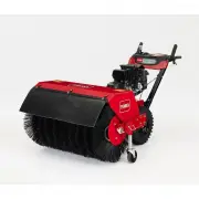
Product Overview g325102 Figure 4 1. Wheel-clutch lever 6. Traction-drive lever 2. Broom-angle lever 7. Fuel-tank cap 3. Broom-drive lever 8. Broom and hood 4. Speed-selector lever 9. Broom-height-adjustmentpin 5. Hand bar grip Controls Determine the left and right sides of the machine fromthe norma...
Page 8 - Specifications; Attachments/Accessories
Wheel-Clutch Levers The wheel-clutch levers are located below the rightand left handles. The wheel clutch levers allow the drive to momentarilydisengage to 1 or both wheels with the traction-drivelever squeezed. This allows for easier turning andmaneuvering the machine ( Figure 6 ). Note: Squeezing ...
Page 9 - Operation; Before Operation; Before Operation Safety; Filling the Fuel Tank
Operation Before Operation Before Operation Safety General Safety • Wear appropriate clothing, including eyeprotection; long pants; substantial, slip-resistantfootwear; and hearing protection; also wear arespirator or dust mask in dusty conditions. Tieback long hair, secure loose clothing, and do no...
Page 10 - Adjusting the Broom Height; During Operation; During Operation Safety
g017922 Figure 8 1. 51 to 102 mm (2 to 4inches) maximum depth 3. Swept area 2. Full broom width 6. If the broom-sweep area is too large, too small,or uneven, adjust the broom height; refer to Adjusting the Broom Height (page 10) . Adjusting the Broom Height 1. Drive to a flat, dusty area and stop th...
Page 11 - Operating the Engine
• Do not operate the machine near glass enclosures,automobiles, window wells, drop offs, etc. withoutproperly adjusting the broom discharge angle. • Do not operate the machine without good visibilityor light. • Look behind and use care when backing up themachine. • Exercise extreme caution when oper...
Page 12 - Opening the Fuel-Shutoff Valve; Starting the Engine; Stopping the Engine
Opening the Fuel-Shutoff Valve Move the fuel-shutoff valve located below the choke,to the right to turn on fuel ( Figure 11 ). g325099 Figure 11 1. F UEL O N position 3. Choke 2. Fuel-shutoff valve Starting the Engine 1. On the right side of the engine, rotate the engineOn/Off switch clockwise to th...
Page 13 - Driving the Machine; CAUTION; Driving Forward
3. Allow the engine to run for a minimum of 15seconds, then turn the engine On/Off switch tothe O FF position to stop the engine ( Figure 12 ). 4. Wait for all moving parts to stop before leavingthe operating position. 5. Use the fuel-shutoff valve to shut off fuel whenyou will not use the machine f...
Page 14 - Driving the Machine Rearward; Operating the Broom; DANGER
g326522 Figure 17 Note: When you complete the turn, release the wheel-clutch lever. The traction driveengages both wheels. • Momentarily squeeze and release the leftor right wheel-clutch lever to make steeringadjustments and keep the machine movingin a straight line, especially in deep snow. 5. To s...
Page 15 - Clearing a Clogged Broom (page
WARNING Contact with a rotating broom can resultin serious personal injury or death to theoperator or bystanders. • To remove an obstruction from the broom;refer to Clearing a Clogged Broom (page 16) . • Do not operate the machine if the broomdrive lever is not functioning properly.Contact your Auth...
Page 16 - Clearing a Clogged Broom; After Operation; After Operation Safety
• 19° to the left • Straight ahead • 19° to the right 5. Once the broom is positioned, release thebroom angle lever. Important: Ensure that the broom locks into place at one of the 3 positions. 6. Release the left wheel-clutch lever. Using the Alternate CasterLocation When working in snow, move the ...
Page 17 - Transporting the Machine
Preventing Freeze-up afterUse • In snowy and cold conditions, some controls andmoving parts may freeze. Do not use excessiveforce when trying to operate frozen controls. If youhave difficulty operating any control or part, startthe engine and let it run for a few minutes. • After using the machine, ...
Page 18 - Maintenance; Maintenance Safety; Preparing for Maintenance
Maintenance Note: Determine the left and right sides of the machine from the normal operating position. Recommended Maintenance Schedule(s) Maintenance Service Interval Maintenance Procedure After the first 2 hours • Check the traction cable adjustment and correct it if necessary.• Check the broom d...
Page 19 - Lubrication; Engine Maintenance; Servicing the Air Cleaner
g023810 Figure 22 1. Spark-plug wire Lubrication Lubricating the Broom-Angle-LockPin and the Hex Shaft Service Interval: Every 100 hours Yearly 1. Lubricate the broom-angle-lock pin fitting withNo. 2 lithium grease ( Figure 23 ). g325097 Figure 23 1. Broom-angle-lock pin 2. Remove the belt cover and...
Page 20 - Checking the Engine-Oil Level
2. Remove the cover and clean it thoroughly( Figure 25 ). Note: Be careful to prevent dirt and debris from falling into the base. g023795 Figure 25 1. Air-filter base 4. Cover 2. Paper air filter 5. Latch on the air-cleanercover (2) 3. Foam pre-cleaner 3. Remove the foam pre-cleaner, wash it with am...
Page 21 - Changing the Engine Oil; Checking the Spark Plug
g023794 Figure 28 1. Filler neck 2. Dipstick 3. Remove the dipstick and wipe off the oil with aclean rag. 4. Insert the dipstick into the filler neck, rest it onthe oil filler neck, and turn it counterclockwiseuntil the cap drops down to lowest point of thethread leads. Note: Do not thread the cap o...
Page 22 - Fuel System Maintenance; Draining the Fuel System
Spark-plug gap: 0.76 mm (0.030 inch) 1. Disconnect the spark-plug wire from the terminalof the spark plug ( Figure 22 ). 2. Clean the area around the base of the sparkplug. 3. Remove the spark plug from the cylinder headby rotating the plug counterclockwise. 4. Examine the plug for wear and damage (...
Page 23 - Drive System Maintenance; Checking the Tire Air Pressure
g325110 Figure 32 1. Side port of the carburetorbowl 2. Drain bolt 4. Install the drain bolt into the side port of thecarburetor. 5. Start the engine and run it until it runs out of fuel. Drive System Maintenance Checking the Tire Air Pressure Service Interval: Every 50 hours Yearly or before storag...
Page 24 - Adjusting the Traction Cable; Broom Maintenance
Adjusting the Traction Cable 1. Loosen the jam nut ( Figure 34 ). g325108 Figure 34 1. Adjuster tube 3. Spring-tension adjuster 2. Jam nut 4. Spring 2. Rotate the spring-tension adjuster until the cableis taught ( Figure 34 ) and the bottom of the bracket touches the top plate of the machine( Figure...
Page 26 - Adjusting the Broom Drive Cable; Belt Maintenance; Removing the Belt Cover; Installing the Belt Cover
Adjusting the Broom Drive Cable 1. Loosen the jam nut ( Figure 40 ). g325107 Figure 40 1. Adjuster tube 3. Spring-tension adjuster 2. Jam nut 4. Spring 2. Rotate the spring-tension adjuster until youmeasure a 1.5 mm (1/16 inch) gap between theframe and the broom clutch arm ( Figure 40 and Figure 41 ...
Page 27 - Replacing the Broom Drive Belt; Removing the Broom-Drive Belt
Checking the Condition of theBelts Service Interval: Every 50 hours 1. Remove the belt cover; refer to Removing the Belt Cover (page 26) . 2. Check the 2 belts for damage or wear. Note: Replace damaged or excessively worn belt(s); refer to Replacing the Broom Drive Belt (page 27) and Replacing the T...
Page 28 - Installing the Broom Drive Belt; Replacing the Traction Belt; Removing the Traction Belt
Installing the Broom Drive Belt Owner provided materials: medium-strengththread-locking compound 1. Assemble the washer over the capscrew (3/8 x2 inches), and apply a coat of medium-strengththread-locking compound to the threads of thecapscrew. 2. Assemble the belt 96 cm (37-1/4 inch) into thegroove...
Page 29 - Installing the Traction Belt
g326387 Figure 47 1. Flange-head capscrew(1/4 x 5/8 inch—loosen) 4. Flange (side plate) 2. Bottom cover 5. Rear cover 3. Flange-head capscrew(1/4 x 5/8 inch) 6. Remove the 6 flange-head capscrew (1/4 x5/8 inch) that secure the bottom cover to themachine, and remove the cover ( Figure 47 ). 7. Slip t...
Page 30 - Chassis Maintenance; Checking for Loose Hardware; Storage; Storage Safety; Preparing the Fuel System; Preparing the Chassis
g326387 Figure 51 1. Flange-head capscrew(1/4 x 5/8 inch—loosen) 4. Flange (side plate) 2. Bottom cover 5. Rear cover 3. Flange-head capscrew(1/4 x 5/8 inch) 5. Assemble the bottom cover to the machine( Figure 51 ) with the 6 flange-head capscrew (1/4 x 5/8 inch). 6. tighten the 2 top flange-head ca...
Page 32 - Troubleshooting
Troubleshooting Problem Possible Cause Corrective Action 1. The fuel tank is empty. 1. Fill the fuel tank. 2. The fuel-shutoff valve is closed. 2. Open the fuel-shutoff valve. 3. The throttle and choke are not in the correct position. 3. Ensure that the throttle control is midway between the Slow an...
Page 35 - California Proposition 65 Warning Information
California Proposition 65 Warning Information What is this warning? You may see a product for sale that has a warning label like the following: WARNING: Cancer and Reproductive Harm—www.p65Warnings.ca.gov. What is Prop 65? Prop 65 applies to any company operating in California, selling products in C...


 Toro 36003
User Manual
Toro 36003
User Manual
 Toro 37799
User Manual
Toro 37799
User Manual
 Toro 37805
User Manual
Toro 37805
User Manual
 Toro 38474
User Manual
Toro 38474
User Manual
 Toro 38475
User Manual
Toro 38475
User Manual
 Toro 38752
User Manual
Toro 38752
User Manual
 Toro 38753
User Manual
Toro 38753
User Manual
 Toro 38755
User Manual
Toro 38755
User Manual
 Toro 38756
User Manual
Toro 38756
User Manual
 Toro 38757
User Manual
Toro 38757
User Manual
 Toro 38838
User Manual
Toro 38838
User Manual
 Toro 38842
User Manual
Toro 38842
User Manual
 Toro 38844
User Manual
Toro 38844
User Manual
 Toro 38890
User Manual
Toro 38890
User Manual