Page 2 - Spis treœci; Hinweise zum Gebrauch
2 Contents / Inhalt / Table des Matières / Spis treœci Page 4 13 14 14151616 16 16 17 1718 19 1921 22 22 22 24252626272930 3132 3232 333334 3435 37 GB DE EINFÜHRUNG Hinweise zum Gebrauch EINBAU Einbauort für die KochfelderVerankerung des KochfeldsElektrischer AnschlussEinbauort für den Ofen Glasmera...
Page 4 - Opis urz1dzenia
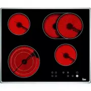
Introduction / Einführung / Présentation / Opis urz¹dzenia Model VTN DC 1 1,200 watt hotplate.2 1,800 watt hotplate.3 700/2,100 watt double circuit hotplate.4 1,800 watt hotplate.5 Residual heat indicator lights.* Maximum electric power: 6,900 watts. Modell VTN DC 1 Kochzone 1200 W2 Kochzone 1800 W3...
Page 13 - Guide to Using the Instructions Booklet; You should keep the Guarantee
GB 13 Guide to Using the Instructions Booklet Dear customer, We are delighted that you have put yourtrust in us. We are confident that the new hob thatyou have purchased will fully satisfy yourneeds. This modern, functional and practicalmodel has been manufactured using top-quality materials that ha...
Page 14 - Important; Positioning the hobs; Installation
GB 14 Important INSTALLATION AND SETUP SHOULDBE CARRIED OUT BY AN AUTHORISEDTECHNICIAN IN LINE WITH CURRENTINSTALLATION STANDARDS. Positioning the hobs Depending on the model to be installed, anopening with the dimensions shown in fi-gure 2 will be cut into the unit’s worktop. The system for fixing ...
Page 15 - Fixing the hob; Protective cover
GB 15 space of at least 20 mm should be left atthe back of the cupboard. As an alternati-ve to this type of panel, you can install adetachable protective cover to the bottomof the hob, which can be obtained from ourTechnical Services using the reference in-dicated. When hobs are handled before being...
Page 16 - See the corresponding manual.; Ceramic hobs with controls; Joining the hob to the oven; Turn off the electricity.
GB 16 The clips and the sealing joint are provi-ded, and can be found in the packaging. Connecting the electricity Before connecting the hob to the electricmains, check that the voltage and fre-quency of the mains matches what isshown on the hob’s rating plate, which islocated lower down, and on the...
Page 17 - Rear view of the Control Panel:; Connecting the gas
GB 17 5 To make the electric connection betwe-en the two appliances, attach the hob’sconnector to oven’s connector. 6 Complete the definitive positioning ofthe oven, ensuring that the cardan teles-copic shafts are firmly in position andthat the telescopic pipes are well-alig-ned when inserted so tha...
Page 18 - . Where air is not available, soapy; Gas conversion; Information for Technical Assis-; whenever the type of gas or the ap-; adjust the minimums; Turn the burners on to their minimum.; Table 1
GB 18 pipe, a maximum torque of 300 Kgf * cmshould be applied. When the gas connection has been made,the installation should be checked to ensu-re that it is completely sealed. If the checkis done using air, care should be taken thatthe test pressure is no more than 200g./cm 2 . Where air is not ava...
Page 19 - Technical information; Dimensions and Characteristics
GB 19 Technical information Dimensions and Characteristics TT VT TC Models 620 60.3 Hob dimensions Height (mm) 65 65 67 65 Length (mm) 600 600 600 600 Width (mm) 510 510 510 510 Dimensions of the placement in the unit Length (mm) (L) 560 560 580 580 Width (mm) (W) 490 490 492 492 Depth (mm) 61 61 63...
Page 21 - Technical details; CHARACTERISTICS OF THE VT DUAL.1; Before installation, make sure that the; A gas cooking appliance produ-; Table 2
GB 21 Technical details CHARACTERISTICS COMMON TO ALLMODELS The supply voltage and frequency will beas shown on the rating plate. CHARACTERISTICS OF THE VT DUAL.1 Warnings: a) Before installation, make sure that the local supply conditions (the gas type andpressure) are compatible with the applian-c...
Page 22 - The apparatus is not designed to; Touch control user; CONTROL ELEMENTS; (also shows that locking is activated on; Use and Maintenance
GB 22 Special requirements before first use Before connecting the hob to the electricmains, check that the voltage and fre-quency of the mains matches what isshown on the hob’s rating plate, which islocated lower down, and on the guaranteeor, where appropriate, the technical datas-heet supplied, whi...
Page 23 - SWITCHING THE APPLIANCE ON
GB 23 Light indicating the hotplate's double circuit is on (only next to double circuithotplates). In triple circuit hotplates,there are two indicator lights, one foreach additional circuit. Indicator light for timed hotplate (Models TR 640, TC 620, TT 640, TR 735 AB andTR 641). Keylock indicator li...
Page 24 - Double and Triple Circuit
24 GB press) and to increase the power (touchwhen the hotplate is already switched on). The power sensor needs to be touched wi-thin 5 seconds after choosing the hotplate,or the hotplate will switch off and will haveto be enabled again. Sensors and are repetitive, so if you keep your finger on them,...
Page 25 - Locking the Hob's Sensors
25 GB 4 On model TR 735 AB, if once the second circuit is in operation you then wish toactivate the third circuit, touch the sen-sor (6) once again. Once you have done this, the second pilot light (10) willcome on. Models TT 630, TC 620 and TR 641: The double circuit may be activated or de-activated...
Page 26 - Cancelling the locking function; Safety disconnection; SWITCHING HEAT-UP FUNCTION ON; Table 4
GB 26 locking function will be reactivated and willreappear the next time the touch control isactivated. Cancelling the locking function Locking can be permanently deactivatedby touching sensor (4) for 5 seconds immediately after activating the touch con-trol. This should be done within 5 secondsaft...
Page 27 - SWITCHING HEAT-UP FUNCTION OFF; Timer Function; Switching on the clock
GB 27 dicator will flash on and off, alternating bet-ween 9 and A , then decrease it to power 6 using sensor . The system will keep the hotplate at power 9 (maximum) for 2.5 mi- nutes, flashing on and off alternately bet-ween 6 and A , then (after 2.5 mins.) it will automatically decrease to constan...
Page 29 - The clock as a; Switching on the counter
GB 29 to set, or (4) to decrease it (from 1 to 99 minutes). You can keep your fingeron the or sensors (7/4) to make the minutes pass by automatically tomake your selection more quickly. The clock will begin to control the time au-tomatically. The control display (11) co-rresponding to the timed area...
Page 30 - Power surges
1 Touch the clock sensor (7) various times, until the pilot light (14) underne-ath the clock indicators (8) lights up. 2 Use the or sensors (5/4) to alter the time. The countdown timer is activated, eventhough the hob is disconnected, until it hascounted down the time required, or untilyou turn it o...
Page 31 - Abnormally high power surges; DOUBLE CIRCUIT INSTRUCTIONS
GB 31 termittent beeping will sound. One of thefollowing messages will appear intermit-tently on the hotplates' displays *. ó * On models TR 640 and TT 640 the digit E will not appear, since these models only havethree power indicators for the hotplates. When normal power resumes, the beepingand the...
Page 32 - RESIDUAL HEAT INDICATORS; Anti-accidental turn system; if the control has not previously; Igniting the burners
GB 32 To only have the inside ring turned on, turnthe control knob clockwise and set it to theposition you require. To turn on the wholehotplate, set the control to position “12”and go on turning, gently, until it goes past“0” and you hear a “CLICK”. Then set thecontrol to the position required. Whe...
Page 33 - Suggestions for using
GB 33 If a gas smell is noted, the gas intake tothe hob should be shut off and the roomventilated. The gas installation and the hobshould also be checked by a specialisedtechnician. Use flat-bottomed pans and check thatthey sit squarely on the grid, so that whenfood boils the pan does not slip (do n...
Page 34 - Advice on using the
GB 34 Cleaning and care the burners * The grids should be cleaned with a non- abrasive scourer when they have cooleddown. * The burners - the grooves in particular - should be cleaned at regular intervals;they should be put into warm, soapywater and cleaned with a scourer or a stiff brush. * Do not ...
Page 35 - Avoid spilling sugar, or products; Cleaning and care; CLEANING AND CARE THE GLASS; dirt and grease; RECOMMENDED CLEANING PRODUCTS
GB 35 * Pans should be made of a material which is heat-resistent so that they donot melt on the glass. * The glass will tolerate bangs from big pans that do not have sharp edges. Becareful with impacts from small, sharpinstruments. Avoid spilling sugar, or products containing sugar, on the glass, s...
Page 37 - If something doesn’t work; Fault; Message ER 21 on the control and subsequent disconnection
GB 37 If something doesn’t work Before calling the Technical Service, pleasemake the following checks: Fault Possible cause Possible solution Message ER 21 on the control and subsequent disconnection If, whilst cooking, the tempe- rature of the control electro- nics gets too high, it will dis- conne...
Page 38 - The gas burners are making the pans dirty
GB 38 Fault Possible cause Possible solution Gas is not coming through to the hob Check that the gas cylinder tap is properly positioned and open If it is piped gas, open the gas tap The gas burners are making the pans dirty The burner openings are dirty Clean the burners’ openings The injector or i...
Page 39 - Teka Küchentechnik GmbH; TEKA GROUP
Teka Industrial, S.A. Cajo, 1739011 Santander (Spain)Tel.: 34-942 35 50 50Fax: 34- 942 34 76 94http://www.teka.net C o d e .: 6 1 4 0 1 1 4 6 / 7 4 2 Teka Küchentechnik GmbH Sechsheldener Str. 12235708 Haiger (Germany)Tel.: 49 - 2771 - 8141-0Fax: 49 - 2771 - 8141-10http://www.teka.net AustraliaAustr...