Page 2 - User’s Guide to this Instruction Manual
Dear Customer, Thank you for choosing a TEKA hob. We are sure that our product will fully s atisf yyour r equirements. This modern, functional and practical applian-ce has been bui lt using top quality m aterialswhich are subjected to strict qual ity contro l sthroughout the manufacturing process. B...
Page 3 - Contents
Introduction Página 4 Description of the Appliance 4 Installation 9 Positioning of the hobs 9 Positioning of the oven 10 Anchoring of the hob 10 Connecting the hob to the oven or the control panel 11 Gas Connection 12 Electrical Connection 13 Gas transfor mation 14 Technical Information 16 Dimension...
Page 4 - Introduction; Description of the Appliance
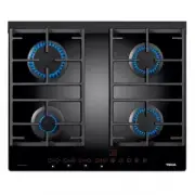
CG. 1 4G (See drawing 1) 1 Auxiliar y bur ner of 860 Kcal/h - 1 kW. 2 Sem i f as t b ur ne r of 1,5 00 Kcal/h - 1.75 kW. 3 Fast burner of 2,580 Kcal/h - 3 kW 4 Semi fast burner of 1,5 00 Kcal/h - 1.75 kW. • All burners incorporate a pan suppor t. • Maxi mum ca lorif ic po wer: 6,4 00 Kca l/h -7.5 kW...
Page 9 - Impor tant; Installation; Positioning of the hobs
9 Impor tant I N S TA L L ATIO N AND AD JUSTMENT MUST BEC ARRIED OUT BY AUTHORISED TECHNICALPERSONNEL ACCORDING TO THE APPLICABLEINSTALLATION REGULATIONS. Depending on the model to be installed ana p e rt u re wi ll be mad e in the wo rkto p, of thed imensio ns specified in the drawing 10. At em pla...
Page 10 - Positioning of the oven
See th applicable manual. Once the hob position has been dimensioned,the seal (J) must be af fixed to the lower par tof the cooke r. Thi s is fa st ened by means offour clamp s (G), each of wh ich has tw o ta bs( P) which are i nser ted in the aper t u r es (O) inthe hob until th ey click into place...
Page 12 - Gas Connection
3 Remove the four lockpins from the ends (B). 4 P a r tially inser t the oven in its position, taking c a re not to snag the telescopic universaljoints which are hanging from the undersideof the hob, and leave sufficient space to beable to connect the other ends of the jointsto the rods at the rear ...
Page 13 - Electrical Connection
The gas connection between the hob and them ains gas pipe mu st be in a ccordance w iththe basi c r egulati ons f or gas install ations inhomes. T E K A will not accept responsability for faults o r dama ge ca us ed by incor r ect or defe ctiveinstalation. O nc e the gas connetio n has bee n made th...
Page 14 - Gas trasformation
14 Impor tant! The transformation of the appliance to use ad i ff e r ent gas to th at fo r wh ich it has b eensold must only be carri ed out by a qualifiedtechnician. I n f o rmation for the Technical Serv i c e : in the e vent of co nv ersio n of the type o f gas or p re s s u re in the appliance,...
Page 16 - Technical information; Dimensions and powers
16 Technical information Dimensions and powers M o d e l s CG Lux-60 4G AI CG.1 4G CG.1 3G. 1P. CG Lux-60 CG Lux-60 CGC CGC 4G CG Lux-70 4G. AIAL 4G. 4G AI AL 4G. D i m e n s i o n s Length (mm) 5 9 0 5 9 0 6 1 0 6 1 0 6 0 0 6 0 0 7 1 0 Width (mm) 5 1 0 5 1 0 5 1 0 5 1 0 5 1 0 5 1 0 5 1 0 High (mm) ...
Page 18 - Technical Data; Table 2
18 COMMON CHARACTERIS TICS TO THE ELEC-TRIC HOTPLATES AND AUTOMATIC LIGHTINGMODEL Th e supp ly vo ltage and freq uenc y mu st be t hose indi cated in the rati ng plate . The fir ep r ot ec t ion i s o f “X ” ty p e. T he ho b mu st beinstalled at over 15 cm away from the side walls.(See drawing 18)....
Page 19 - Table 3
19 COMM ON C HARACTERISTIC S TO EVERYMODEL N .B.: All the hob mode ls re f e r r ed to in thismanual ha ve hot zon es during or a fter thei r use and can cause burns. Care must be taken when handling these hobsb e f o re installati on as there ma y be r o u g hzones or corners which may be dangerous...
Page 24 - Use and Maintenance; Special requirements
Before connecting the hob to the power supplycheck that the voltage and f requency ar e tho-se indicated in the rating plate located on thelower par t of the hob. Remo ve th e protec ting plastic af fix ed to thehob, if any. Pan suppor t supplement Pan suppor t Burner cover Burner head Gas nozzle No...
Page 26 - Switching on Electric Hotplates
The minimum diameter of the pans to be usedis 140 mm. For pans of 120 mm diameter orless, use t he smal l bur ner with the pan sup-por t supplement. Th e e lec tric hotp lates ar e co ntrolle d by aseven step switch. To obtain dif f e rent powersthe cor r espo ndin g contr ol must be tur ned tothe d...
Page 27 - Components of a Safety System
27 On al l t he ho bs which in corp orat e th e saf et yf e a t u re (models with initi als AL), the gas cut-o f f s ystem is co mprised form ed by th e follo-wing elements: (See drawing 24). • Safety tap • Safety thermocouple next to the burner • Ther mocouple-tap connection The thermocouple sends ...
Page 28 - Using your Hob
28 • When cooking with a griddle pan, stonewa-re pots or p ans which r eflec t he at d own-wards, you must use the pan support sup-pl ement, ot her w ise t he excessi ve t e m p e r a t u re which is reflected downward smay damage the hob glass or the burners. • The pan suppor t supplement can be us...
Page 29 - Hints for the Corr ect Usage
• D o n ot use lar ge bur ners with pans ofs mall di ameter s as par t of the fl ame willbe d eflec ted ar oun d the o utsid e of thepan, thus considerably r educing ef f i c i e n c y(See drawing 27). Right Wrong • Lit bur ners must not be left uncovered, ino rd er to avoi d th e w astage o f ga s ...
Page 30 - Reminder
Do not use small pans on large burners, as the fla-me will be dissipated. Use appropriately sized pans for each burn e r, thusmaking the best use of the heat. Do not place pans unevenly on the pan suppor t. Place the pan correctly over the centre of the burn e r. Do not use pa ns which r e flect exc...
Page 31 - Cleaning and Conser vation
For the cor rect conser vation of the hob glassit must be cleaned usi ng the appropriate pro-du c ts an d ut en sil s a nd when t he gla ss isc o ld. C lea n ing is ea sie r if i t i s d on e ea chti me t he ho b is use d , th us pr even ti ng t hebuild- up of dir t . The cleaning of the hob gl ass ...
Page 32 - Maintenance
B e f o r e cl eaning, discon nect the app li ancefrom the mains supply. El ectric h otplates should be cleaned wi thsoapy water a nd a non -abra si ve scoure r. If ,after cooking, the st ai nless stee l ring o f the hotplate or cooker frame is seem to be slightlyyellow, this may be cleaned using le...
Page 33 - If Something Doesn’t Work
33 Fault Possible Cause Solution Neither the hob nor the pilot light works. The mains cable is not connected. Connect the mains cable. No spark appears when the automatic ignition switch is pressed. Power is not reaching the plug. Check / repair the mains supply. A spark appears but the burner does ...