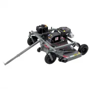
Page 2 - LIMITED WARRANTY
LIMITED WARRANTY The manufacturer’s warranty to the original consumer purchaser is: This product is free from defects in materials and workmanship for the period's shown below beginning from the date of purchase by the original consumer purchaser. We will repair or replace, at our discretion, parts ...
Page 3 - SAFETY PRECAUTIONS; Thank you for choosing Swisher’s 44” Trail Cutter. Before operating; Never allow children to operate this machine.; Never assume that children will remain where you last saw them; Always look down and behind before and during backing.
SAFETY PRECAUTIONS This Safety Alert Symbol indicates important messages in this manual. When you see this symbol, carefully read the message that follows and be alert to the possibility of personal injury. Read this manual completely. This machine can amputate hands and feet, and throw objects. Fai...
Page 4 - ASSEMBLY; Tools Required
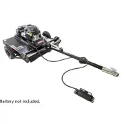
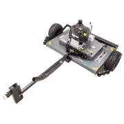
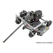
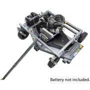
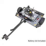
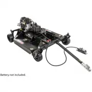
• Insert 5/8-11 X 2 ½ bolt through the top of pivot assembly and top link and secure with 5/8-11 nut. Insert 5/8-11 x 2½ bolt through the tabs on the top of the Hitch bar and Top Link. Secure with a 5/8-11 lock nut. • Place 2” Hitch Coupler on the end of the Hitch Bar. Align Holes with Hitch Bar and...
Page 5 - OPERATING YOUR TRAIL CUTTER; INTENDED USE
5 OPERATING YOUR TRAIL CUTTER The operation of any mower can produce foreign objects to be thrown into the eyes, resulting in severe eye damage. Always wear certified safety glasses or wide-vision safety goggles over spectacles before starting any cutting machine and while operating such a machine. ...
Page 6 - STARTING THE ENGINE; “ENGAGED”; BREAKING IN YOUR CUTTER
6 CAUTION: SHUT OFF THE CUTTER ENGINE AND REMOVE SPARK PLUG WIRE FROM SPARK PLUG BEFORE MAKING ANY ADJUSTMENTS TO THE CUTTER. STARTING THE ENGINE See engine manufacturer’s recommendations for the type and amount of oil and fuel used. Trail Cutters equipped with an electric start engine will need a b...
Page 7 - CUTTER HEIGHT ADJUSTMENT; There is approximately 4” of height adjustment.; TOW HITCH OFFSET; Turn key switch to the “OFF” position.; SUGGESTED CUTTING PRACTICES
7 CUTTER HEIGHT ADJUSTMENT • There is approximately 4” of height adjustment. • Rotate height adjust crank handle in a clockwise direction to lower the mower deck. Rotate counterclockwise to lift the mower deck. • Dense areas should be cut twice. • Push handle down to lock height position. • Adjust t...
Page 8 - CUTTER MAINTENANCE
CAUTION: DO NOT HANDLE CUTTER BLADES WITH BARE HANDS. CARELESS OR IMPROPER HANDLING MAY RESULT IN SERIOUS INJURY. 8 GENERAL RECOMMENDATIONS The warranty on this cutter does not cover items that have been subjected to operator abuse or negligence. To receive full value from the warranty, operator mus...
Page 9 - GENERAL TROUBLESHOOTING
The unit is not cutting level. • Level deck. Check air pressure of all tires; make sure they are equal. See tires for maximum inflation. • Without the engine running, make certain blades are installed identically. The engine will not start. • Disengage blades, turn key switch to the “OFF” position, ...
Page 10 - SAFETY AND OPERATIONAL DECALS
SAFETY AND OPERATIONAL DECALS Replace decal immediately if damaged. OD29-DANGER DECAL OD33-5MPH DECAL OD36-DEFLECTOR DECAL OD55-DANGER DECAL OD45-WARNING DECAL OD129-ENGAGE DECAL OD28-OFF/RUN/START DECAL 10 OD99112 LARGE SWISHER LOGO
Page 11 - DECK LEVELING DIAGRAM; FIGURE 1; FRONT TO BACK ADJUSTMENT
11 UNCRATING & SET-UP DIAGRAM DECK LEVELING DIAGRAM FIGURE 1 FIGURE 2 FRONT TO BACK ADJUSTMENT For best cutting results, the cutter deck should be parallel to the ground. To check parallel adjustment, measure the distance from the bottom edge of the deck in both the front and rear of the deck. T...
Page 12 - FRONT SKIRT ASSEMBLY; FIGURE 3; HITCH ASSEMBLY; FIGURE 4
When ordering replacement parts* = USE PAINT CODE: TK=BLACK Item # Description Part # 1 Nut - Serr Flange, 1/4-20 Grade 5 ZY NB524 2 Rubber Flapper 10384 3 Washer - Fender, 1/4X1 1/4OD Gr 2 ZY 11520 4 Bolt - Serr Flange, 1/4-20 X 3/4 GR5 ZY NB690 5 Nut - Serr Flange, 1/4-20 Grade 5 ZY NB180 6 Plate ...
Page 13 - FIGURE 5
Item # Description Part # 1 Nut - 5/16-18 Serrated Flange NB170 2 Nut, Push - 5/16 NB117 3 Knob Height Adjustment H7K 4 Height Adjust Rod 4006 5 Bolt - 1/2-13 X 1 1/2 10046 6 1/2-13 Jam Nut NB118 7 Washer - Bellville, .512x1.26x .138 10291 8 1/2 NR Mach Bushing 14 GA NB177 9 Screw - .312-18 x .75 26...
Page 14 - Z Bracket, Jack Support; DECK ASSEMBLY; FIGURE 6
14 Item # Description Part # 1 Deck - Weldment 15727* 2 Screw - .312-18 x .75 26X249 3 Side Gusset - Left 15056* 4 Nut - 5/16-18 Serrated Flange NB170 5 Side Gusset - Right 15057* 6 Z Bracket, Jack Support 15055* 7 Front Rail/Deck Support 15054* 8 Rail - RT44, Right 17358* 9 Weldment - Blade Mount 1...
Page 15 - BLADE DRIVER ASSEMBLY; FIGURE 7
Item # Description Part # 1 Nut - Nyloc 1"-8 NB612 2 Washer - 1" X 2" X 14GA NB738 3 Pulley - Blade, 10.3125" 4846 4 Spacer - Pulley 21344 5 Bearing - Blade 4845 6 Shaft - Blade 18844 7 Nut - Nyloc 1/2"-13 NB281 8 Washer - USS Flat, 1/2" NB555 9 Blade Driver Housing 4858* 10 ...
Page 16 - FIGURE 8; FIGURE 9; IDLER CONFIGURATION; ENGINE PULLEY/BELT ASSEMBLY
16 FIGURE 8 Item # Description Part # 1 Nut - Nyloc 3/8-16 ZY NB182 2 Washer - SAE Flat 3/8 ZY Carbon Steel NB272 3 Pulley - Idler, OD3.25" ID3/8" B527 4 Nut - HNC, 3/8-16 GR2 ZY NB212 5 Spring - Clutch Rod; T60 682S 6 Eyebolt - Turned 3/8-16 X 5 ZY STD 11223 7 Bolt - 1/2-13 X 2 1/2 HCC GR5 ...
Page 18 - Cable Tie - Carbon Canister; REPAIR PARTS; Mowers equipped with a 14.5HP engine
18 Item # Description Part # 1 Bolt - Serr Flange 1/4-20 X 1 3/4 18236 2 Cap - Fuel 18221 3 Bracket - Fuel Tank 18225 4 Fuel Tank - 2.5 Gallon 18214 5 Washer - SAE Flat 1/4 NB274 6 Nut - Nyloc 1/4-20 NB180 7 Cable Tie - Carbon Canister 18219 8 Carbon Canister - 2.50 Gallon 18224 9 Bolt - 10-24 X 3/4...
Page 19 - BATTERY HOLDER CONFIGURATION; Note; lid in the open position as shown in; Lid Closed Position
BATTERY HOLDER CONFIGURATION When ordering replacement parts* = USE PAINT CODE: TK=BLACK Note : Use Thumbscrew [item #3] to hold lid in the open position as shown in illustration above. 19 Lid Closed Position Lid Opened Position FIGURE 14 FIGURE 15 Mower require a U1 battery (not included). Item # D...
Page 20 - BCS; BATTERY CABLE ASSEMBLY; Mower not shown for Clarity
Item # Description Part # 1 Cable - Black 10" BCS 2 Nut - M8 x 1.35 Zinc NB718 3 Bolt - HH M8 x 1.25 NB719 BATTERY CABLE ASSEMBLY When ordering replacement parts* = USE PAINT CODE: TK=BLACK 20 Mower not shown for Clarity FIGURE 16 Mower require a U1 battery (not included).
Page 21 - Unlocked
RECOMMENDED HITCH CONFIGURATIONS AND POSITIONS FIGURE 20 Unlocked FIGURE 21 Locked FIGURE 17 FIGURE 18 FIGURE 19 21
Page 23 - SWISHER ACQUISITION INC.; OWNER’S; CHANGING YOUR LANDSCAPE SINCE 1945
44” COUNTRY CUT TRAIL CUTTER Each mower has its own model number. Each engine has its own model number. The model number for the mower will be found on the right hand side of the motor mount. The model number for the engine will be found on the top of the valve cover.All mower parts listed herein ma...