Page 2 - LIMITED WARRANTY
The manufacturer’s warranty to the original consumer purchaser is: This product is free from defects in materials and workmanship for the period's shown below beginning from the date of purchase by the original consumer purchaser. We will repair or replace, at our discretion, parts found to be defec...
Page 4 - SAFETY PRECAUTIONS
This Safety Alert Symbol indicates important messages in this manual. When you see this symbol, carefully read the message that follows and be alert to the possibility of personal injury. Read this manual completely. This machine can amputate hands and feet, and throw objects. Failure to observe the...
Page 5 - KNOW YOUR CUTTER; CONTROL CONSOLE; manual for detailed operational and safety information.
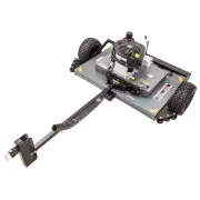
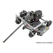
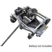
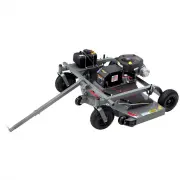
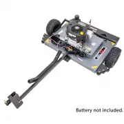
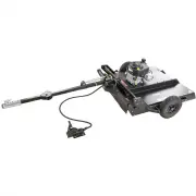
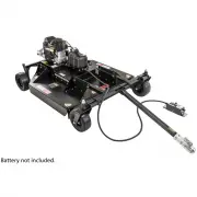
5 KNOW YOUR CUTTER ** REMOVABLE COVER • Battery, Solenoid & Wiring are located under the tool-free removable cover. • Serial Number Tag is located next to the battery. Remove cover to access serial number. HEIGHT ADJUSTMENT HANDLE RIGHT SIDE HEIGHT ADJUSTMENT HANDLE LEFT SIDE REMOVABLE COVER(SEE...
Page 6 - GENERAL OPERATIONS
6 GENERAL OPERATIONS The operation of any mower can produce foreign objects to be thrown into the eyes, resulting in severe eye damage. Always wear certified safety glasses or wide-vision safety goggles over spectacles before starting any cutting machine and while operating such a machine. The opera...
Page 9 - CUTTER MAINTENANCE
CAUTION: DO NOT HANDLE CUTTER BLADES WITH BARE HANDS. CARELESS OR IMPROPER HANDLING MAY RESULT IN SERIOUS INJURY. 9 GENERAL RECOMMENDATIONS The warranty on this cutter does not cover items that have been subjected to operator abuse or negligence. To receive full value from the warranty, operator mus...
Page 10 - TROUBLESHOOTING
IF PROBLEMS PERSIST HAVE A QUALIFIED MECHANIC SERVICE THE CUTTER. NEVER ATTEMPT TO MAKE AN ADJUSTMENT THAT YOU ARE NOT SURE IS CORRECT. DOING SO CAN CAUSE OTHER PROBLEMS. 10 TROUBLESHOOTING ISSUE SOLUTION Disengage blades, turn key switch to the “OFF” position,check battery and all other electrical ...
Page 11 - SPECIFICATIONS
Description Engine 14.5HP (603 CC) Kawasaki Engine Specifications See engine Manual for Specifications Starting Electric Start Battery 12 Volt ("U1" recommended), 340CCA Fuel 2.5 Gal. (9.46 L), Unleaded Gasoline (MIN 87 Octane)MAX 10% Ethanol Overall Dimesions 139.5" L x 47" W x 34...
Page 12 - SAFETY AND OPERATION DECALS
Replace decal immediately if damaged. Order by part number from Swisher. 1-800-222-8183, 8-5 CT M-F OD29-DANGER DECAL OD33-5MPH DECAL OD36-DEFLECTOR DECAL OD55-DANGER DECAL OD45-WARNING DECAL OD129-ENGAGE DECAL OD28-OFF/RUN/START DECAL 12 OD99112 LARGE SWISHER LOGO SAFETY AND OPERATION DECALS
Page 13 - ASSEMBLY PARTS
Before assembling the Cutter make sure that all assembly parts are present. Item # Description Part # Qty 1 Key Set ( 2 Keys) KSK 1 2 Nut - 1/4-20 Flange NB524 2 3 Nut - 3/8-16 Nylon-Insert Lock NB182 2 4 Nut - 3/4-10 Nylon-Insert Lock 21132 1 5 Washer - 3/8 SAE Flat NB272 4 6 Washer - 3/4" SAE ...
Page 14 - Tools Required
14 FIGURE 14.1 FIGURE 14.2 SET-UP DIRECTIONS GENERAL RECOMMENDATIONS • Use at least two people to uncrate & assemble the unit. The cutter and its components are very heavy. UNCRATING • Using a hammer and pry bar, separate the boards of the crate starting with the top. Use caution to not damage t...
Page 15 - BATTERY
CAUTION: USE CARE HANDLING BATTERY. CARELESS OR IMPROPER HANDLING MAY RESULT IN SERIOUS INJURY. 15 GENERAL RECOMMENDATIONS • A standard “U1” Battery is recommended. If the Battery is put into service after the “month and year” of the date on the Battery, it may need to be charged with a 12 volt Batt...
Page 16 - BATTERY CABLES
When ordering replacement parts* = USE PAINT CODE: TK=BLACK 16 Engine shield not shown for Clarity FIGURE 16.1 Cutter requires a U1 Battery (not included). BATTERY WIRING * ALWAYS CONNECT POSITIVE CABLE FIRST WHEN CONNECTING BATTERY* ALWAYS REMOVE NEGATIVE CABLE FIRST WHEN DISCONNECTING BATTERY (See...
Page 17 - HEIGHT ADJUSTMENT
GENERAL RECOMMENDATIONS • Set the Cutter to an appropriate height for the media being cut. Taller/Thicker grass & brush may require a higher first cut and a lower second cut for best results. It’s recommended to cut the second pass perpendicular to the first pass. • Height indicator decal contai...
Page 18 - HITCH OPERATIONS
GENERAL RECOMMENDATIONS • It is recommended to set the hitch bar in the straight position when an offset is not needed. DO NOT ADJUST HITCH ON HILLS. The Cutter may roll once the pins are removed on a slope. This can cause injury or damage the equipment. • The unit can be unattached from the tow veh...
Page 20 - BLADE REPLACEMENT
BLADE REPLACEMENT When ordering replacement parts* = USE PAINT CODE: TK=BLACK 20 FIGURE 20.1 BLADE REMOVAL (See FIGURE 20.1 ) • Disconnect spark plug wire before working on unit! • Use Jack Stands or ramps to lift the Cutter off of the ground. Chock the wheels to prevent the Cutter from moving. • Us...
Page 21 - BELT REMOVAL/INSTALLATION
When ordering replacement parts* = USE PAINT CODE: TK=BLACK 21 REMOVING BELT (See FIGURE 21.2 ) • Disconnect negative Battery • terminal before working on • the Cutter. • Locate the six Screws 7 securing the Belt Cover 6 . Using the 9/16” wrench/socket, remove the screws. • Carefully slide Cover to ...
Page 22 - PARTS DIAGRAMS
22 Item # Description Part # 12 Washer - Belleville, .512x1.26 10291 13 Bearing - Flanged Sleeve 5/8ID 21246 14 Nut - Nylon Lock, 1"-8 NB612 15 Washer - 3/4ID X 1 1/4OD, Flat NB184Z 16 Nut - Nylon Lock Jam, 3/4-10 NB313 17 Nut - Lock Jam, 2 Way 5/8-11 NB595 18 Weldment - Caster Arm 21217* 19 Wel...
Page 23 - FRONT SKIRT ASSEMBLY
When ordering replacement parts* = USE PAINT CODE: TK=BLACK Item # Description Part # 1 Nut - Serr Flange, 1/4-20 NB524 2 Debris Guard - Outer 21233 3 Washer - Fender, 1/4X1 1/4OD 11520 4 Bolt - Serr Flange, 1/4-20 X 3/4 NB690 5 Debris Guard - Center 21234 6 Bolt - Carriage, 1/4-20 10547 7 Plate - H...
Page 24 - ASSEMBLIES
Item # Description Part # 21 Bolt - Serr Flange, 5/16-18 X1 1/4ZY Gr5 NB253 22 Bolt - Serr Flange, 5/16-18 x 3; GR5 ZP 18580 23 Plate - Battery Strap 21252* 24 Cable - Black BCS 25 Battery Pad BATPAD 26 Cable - Red BCSR 27 Nut - M8-1.25 NB718 28 Bolt - M8-1.25 X 20mm NB719 29 Bolt - TCS 1/4-20 X 1/2...
Page 25 - DECK ASSEMBLY
25 Item # Description Part # 1 Plate - Motor Mount Rail Right 21251* 2 Screw - .312-18 X .75, Black 26X249 3 Brace - Rear Z-Rail 16371* 4 Plate - Blade Support 15058* 5 Bolt - Serr. Flange, 3/8-16 13964 6 Plate - Motor Mount Rail Left 21250* 7 Weldment - Deck Body 21230* 8 Nut - Serr. Flange, 5/16-1...
Page 26 - HITCH ASSEMBLY
26 Item # Description Part # 1 Bolt - Hex, 3/4-10 21129 2 Washer - 3/4" SAE NB146 3 Pin - 3/8", Tab Retainer 21225 4 2" Ball Coupler 7365 5 Bolt - Hex, 3/8-16 NB150 6 Washer - 3/8" SAE NB272 7 Nut - Nylon Lock, 3/4-10 21132 8 Weldment - Offset Hitch Tube 21117* 9 Nut - Nylon Lock, 3/...
Page 27 - BLADE DRIVER ASSEMBLY
BLADE DRIVER ASSEMBLY FIGURE 27.1 Item # Description Part # 1 Nut - Nylon Lock, 1"-8 NB612 2 Washer - 1" X 2" X 14GA NB738 3 Pulley - Blade, 12" OD 20920 4 Spacer - Pulley 21344 5 Bearing - Blade 4845 6 Shaft - Blade 18844 7 Nut - Nylon Lock, 1/2"-13 NB281 8 Washer - USS Flat, 1/...
Page 28 - ENGINE PULLEY/BELT ASSEMBLY; IDLER CONFIGURATION
28 ENGINE PULLEY/BELT ASSEMBLY Item # Description Part # 1 Nut - Nylon Lock, 3/8-16 NB182 2 Washer - SAE Flat 3/8 NB272 3 Pulley - Idler, OD3.25" ID3/8" B527 4 Idler - Weldment 21285* 5 Nut - Hex, 3/8-16 NB212 6 Spring - Clutch Rod 682S 7 Bolt - Hex, 1/2-13 X 2 1/2 NB510 8 Nut - Jam Lock, 1/...
Page 31 - NOTES
Page 34 - OWNER’S; CHANGING YOUR LANDSCAPE SINCE 1945
44” BRUSH KING TRAIL CUTTER Each Cutter has its own model number. Each engine has its own model number. The model number for the Cutter will be found on the right hand side of the motor mount. The model number for the engine will be found on the top of the valve cover.All Cutter parts listed herein ...