Sharp R-210B - Manuals
Sharp R-210B Microwave – User Manual in PDF format online.
Manuals:
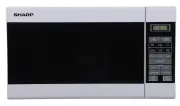
User Manual Sharp R-210B


Summary
2 Twin City IM-4050 Wall Fan Installation 1. Your wall fan is shipped with a wall mounting brack- et. Refer to the wall fan dimensional drawing on page 4 for mounting hole locations. Consideration should be taken when choosing wall fan location with regard to other buildings, parking lots, etc. 2. A...
Twin City IM-4050 3 Roof Fan Installation Downblast Fans: 1. Position the fan with its wiring conduit in line with the wiring coming up through the roof curb and damper (if present). If the fan has an external dis- connect switch, position the fan with the junction box towards the power supply. Upbl...
4 Twin City IM-4050 Figure 3. Low End Setpoint Adjustment NOTE: 5 amp model shown. On 10 and 15 amp models, adjustment is made through clear- ance hole in heat sink. SETPOINT ADJUSTMENT SCREW Table 4. Speed Controller Size Speed Control Installation (Models DCLH, DCLP, DCRD, DCRU, DCRUR, DCRW, DCRWR...
Sharp Microwaves Manuals
-
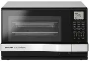 Sharp AX1100JS
User Manual
Sharp AX1100JS
User Manual
-
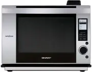 Sharp AX1500JS
User Manual
Sharp AX1500JS
User Manual
-
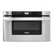 Sharp KB6524PSY
User Manual
Sharp KB6524PSY
User Manual
-
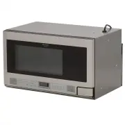
 Sharp R1210TY
User Manual
Sharp R1210TY
User Manual
-
Sharp R1211TY
User Manual
-
 Sharp R1214TY
User Manual
Sharp R1214TY
User Manual
-
 Sharp R1514TY
User Manual
Sharp R1514TY
User Manual
-
 Sharp R1874TY
User Manual
Sharp R1874TY
User Manual
-
 Sharp R1881LSY
User Manual
Sharp R1881LSY
User Manual
-
 Sharp R20A0W
User Manual
Sharp R20A0W
User Manual
-
 Sharp R210DW
User Manual
Sharp R210DW
User Manual
-
 Sharp R211DB
User Manual
Sharp R211DB
User Manual
-
 Sharp R211DW
User Manual
Sharp R211DW
User Manual
-
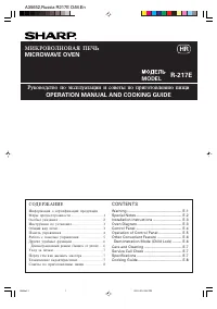 Sharp R-217E
User Manual
Sharp R-217E
User Manual
-
 Sharp R-21LCFS
User Manual
Sharp R-21LCFS
User Manual
-
 Sharp R231ZS
User Manual
Sharp R231ZS
User Manual
-
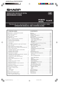 Sharp R-247E
User Manual
Sharp R-247E
User Manual
-
 Sharp R291ZST
User Manual
Sharp R291ZST
User Manual
-
 Sharp R30A0W
User Manual
Sharp R30A0W
User Manual
-
 Sharp R32BST
User Manual
Sharp R32BST
User Manual