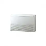
Page 2 - English; Contents; Safety Information; Troubleshooting
2 English Contents Safety Information 3 Installation Procedure 5 Step 1 Checking and preparing accessoriesStep 2 Choosing the installation locationStep 3 Optional: Insulating the body of the indoor unitStep 4 Installing the indoor unitStep 5 Purging inert gas from the indoor unitStep 6 Cutting and f...
Page 3 - ormation; General information; WARNING
3 English Safety Inf ormation WARNING • Hazards or unsafe practices that may result in severe personal injury or death. CAUTION • Hazards or unsafe practices that may result in minor personal injury or property damage. • Carefully follow the precautions listed below because they are essential to gua...
Page 4 - Installing the unit; Power supply line, fuse or circuit; Make sure that you earth the cables.
4 Safety Information English Safety Inf ormation Installing the unit WARNING IMPORTANT: When installing the unit, always remember to connect first the refrigerant tubes, then the electrical lines. • Always disassemble the electric lines before the refrigerant tubes. • Upon receipt, inspect the produ...
Page 5 - Installation Procedure; Do not install the air conditioner in following places.; Installation location requirements; Maintain sufficient clearance around the indoor unit.
5 Installation Pr oc edur e English Installation Procedure Installation Procedure Do not install the air conditioner in following places. • Place where there is mineral oil or arsenic acid. Resin parts flame and the accessories may drop or water may leak. The capacity of the heat exchanger may reduc...
Page 6 - oc
6 Installation Procedure Installation Pr oc edur e English Indoor unit dimensions (Unit: mm) Category Square panel Circular panel Front 1000 358 Ceiling opening dimension 960 (950 - 960) Ceiling opening dimension 960 (950 - 960) 116 1050 883 Large+, Large 385 166 66 357 404 128 181 190 317 Drain hos...
Page 7 - For the recessed installation of the circular panel
7 Installation Pr oc edur e English Spacing requirements A A : 1500 mm or more A A A 'C' mm Indoor unit 2500 mm or more Obstruction 20 mm 1500 mm or more 10 mm (Unit: mm) Model AC071KN4DKH AC090KN4DKH AC100KN4DKH AC120KN4DKH AC140KN4DKH C 261 345 345 345 345 Model AC071KN4DKH AC090KN4DKH AC100KN4DKH...
Page 8 - CAUTION; Step 4 Installing the indoor unit; NOTE
8 Installation Procedure Installation Pr oc edur e English CAUTION • The indoor unit must be installed according to the specified distances in order to permit accessibility from each side, to guarantee correct operation, maintenance, and repair of the unit. The components of the indoor unit must be ...
Page 9 - For the recessed installation of the square panel.; You must install all of the suspension rods.
9 Installation Pr oc edur e English 2 Perform the following steps to install inspection holes in accordance with the panel type. a For the recessed installation of the square panel. • Install an inspection hole to the direction of connection parts of the refrigerant pipe and the drain hose. (1 point...
Page 10 - Place the pattern sheet on the indoor unit.; Step 6 Cutting and flaring the pipes; Slide a flare nut on to the pipe and modify the flare.
10 Installation Procedure Installation Pr oc edur e English 7 Adjust the unit to the appropriate position, taking into account the installation area for the front panel. • Place the pattern sheet on the indoor unit. • Adjust the space between the ceiling and the indoor unit by using a dimension gaug...
Page 11 - There are two refrigerant pipes of different diameters :
11 Installation Pr oc edur e English 5 Check that the flaring is correct, referring to the illustrations below for examples of incorrect flaring. Correct Inclined Damaged Surface Cracked Uneven Thickness Step 7 Connecting the assembly pipes to the refrigerant pipes There are two refrigerant pipes of...
Page 12 - Step 8 Performing the gas leak test; Be sure to wrap insulation tightly without any gaps.; Select the insulation of the refrigerant pipe.
12 Installation Procedure Installation Pr oc edur e English Step 8 Performing the gas leak test To identify potential gas leaks on the indoor unit, inspect the connection area of each refrigerant pipe using a leak detector for R-410A. Before recreating the vacuum and recirculating the refrigerant ga...
Page 13 - Tighten the metal clamp as shown in the picture.
13 Installation Pr oc edur e English Pipe Pipe size Insulation type (heating/cooling) Remarks Standard (Less than 30°C, 85%) High humidity (Over 30°C, 85%) EPDM, NBR Liquid pipe Ø6.35 to Ø9.52 9t 9t The internal temperature is higher than 120°C. Ø12.7 to Ø19.05 13t 13t Gas pipe Ø6.35 13t 19t Ø9.52 1...
Page 14 - Install air ventilation to drain condensation smoothly.
14 Installation Procedure Installation Pr oc edur e English 5 Push the drain hose up to insulation when connecting the drain hose to drain socket. Metal clamp Drain socket Drain hose Large seailng pad Be sure to bond the drainhose and the main pipe. Drain pipe Drain hose PVC Tube Joint + VP25 (OD: 3...
Page 15 - Step 11 Performing the drainage test
15 Installation Pr oc edur e English • Install horizontally. Indoor unit Be horizontal Flexible hose • Max. allowable axis gap. Indoor unit Max. 20 mm • Max. allowable bending angle. Indoor unit Max. 30˚ NOTE • If a concentrated drain pipe is installed, refer to the figure below. Centralized horizon...
Page 16 - Remove the control box cover of the indoor unit.; Reassemble the control box cover.
16 Installation Procedure Installation Pr oc edur e English CAUTION • Only in the Cool mode, you can check the correct operation of the drain pump. When the electric cable connection has not been completed • Remove the control box cover of the indoor unit. • Connect the power supply (220~240V, 50 Hz...
Page 17 - Example) 1phase model; phase
17 Installation Pr oc edur e English Example) 1phase model 1(L) 2(N) L N F1 F2 F1 F2 L N Indoor power Main power cable Communication cable Indoor unit Outdoor unit For connecting the power and communication cables Wire inserthole 3 phase 1(L) 2(N) L1(R) L2(S) L3(T) N F1 F2 F1 F2 L N Indoor power Mai...
Page 18 - Prepare the following tools.; Peel off 20 mm of the wire shields of the tube.; Method 1
18 Installation Procedure Installation Pr oc edur e English Step 13 Optional: Extending the power cable 1 Prepare the following tools. Tools Spec Shape Crimping pliers MH-14 Connection sleeve (mm) 20xØ6.5 (HxOD) Insulation tape Width 19 mm Contraction tube (mm) 70xØ8.0 (LxOD) 2 As shown in the figur...
Page 19 - Apply heat to the contraction tube to contract it.; – Incomplete wire connections can cause electric
19 Installation Pr oc edur e English 5 Wrap it with the insulation tape twice or more and position your contraction tube in the middle of the insulation tape.A total of three or more layers of insulation is required. Method 1 Method 2 Insulation tape 40 mm 35 mm Insulation tape 6 Apply heat to the c...
Page 20 - Cool
20 Installation Procedure Installation Pr oc edur e English 2 Set the option values. CAUTION • The total number of available options are 24: SEG1 to SEG24. • Because SEG1, SEG7, SEG13, and SEG19 are the page options used by the previous remote control models, the modes to set values for these option...
Page 22 - Auto
22 Installation Procedure Installation Pr oc edur e English Steps Remote control display 9 Set the SEG11 and SEG12 values: a Set the SEG11 value by rotating the Wheel counterclockwise until the value you want to set appears on the remote control display. SEG11 b Set the SEG12 value by rotating the W...
Page 26 - Dry
26 Installation Procedure Installation Pr oc edur e English Steps Remote control display 3 Set the SEG4 and SEG5 values: a Set the SEG4 value by pressing the (Low Fan) button repeatedly until the value you want to set appears on the remote control display. SEG4 b Set the SEG5 value by pressing the (...
Page 27 - Heat
27 Installation Pr oc edur e English Steps Remote control display b Set the SEG10 value by pressing the (High Fan) button repeatedly until the value you want to set appears on the remote control display. When you press the (Low Fan) or (High Fan) button, values appear in the following order: SEG10 8...
Page 30 - Common steps for setting the
30 Installation Procedure Installation Pr oc edur e English Setting the indoor unit addresses Option No. for an indoor unit address: 0AXXXX-1XXXXX-2XXXXX-3XXXXX Before installing an indoor unit, be sure to set an address for the indoor unit by taking the following steps: 1 Make sure that the power i...
Page 31 - Setting the installation options in a batch; Common steps for setting the addresses and
31 Installation Pr oc edur e English CAUTION • The main address must be set to a value in the range 0 to 14. If you set other values, communication error will occur. • If any of SEG5 and SEG6 is set to a value in the range A to F, the main address of the indoor unit does not change. • If SEG3 is set...
Page 33 - Example: When installing DPM (1 Outdoor unit with 4 indoor units); Changing the addresses and options individually; Common
33 Installation Pr oc edur e English • Even if you set the Use of drain pump (SEG8) option to 0, it is automatically set to 2 (the drain pump is used with 3 minute delay). • If you set the Maximum filter usage time (SEG18) option to a value other than 2 and 6, it is automatically set to 2 (1000 hour...
Page 34 - Making a circular opening on the ceiling
34 Installation Procedure English Installation Pr oc edur e Optional: For the installation of the circular panel Making a circular opening on the ceiling Use a paper compass printed on the indoor unit package. (attached inside to the upper part) 1 Use a bolt or a pin to fix pivot point of the paper ...
Page 35 - Appendix
35 English Appendix Troubleshooting Appendix Condition Indoor unit display indications Ice blue Yellow green Blue Red Power reset (blinking once every 2 seconds) X X X In the defrost operation (blinking once every 10 seconds) X X X Open or short circuit error of the indoor-temperature sensor X X X E...