Page 2 - TABLE OF CONTENTS; TABLE DES MATIÈRES / ÍNDICE DE CONTENIDO; INTRODUCTION; INTRODUCTION / INTRODUCCIÓN
Page 2 Introduction ....................................................................................................................................... 2 Introduction / Introducción General Safety Rules ..........................................................................................
Page 3 - with the engine running at full speed. Fully; GENERAL SAFETY RULES
Page 3 — English WARNING: Read and understand all instructions. Failure to follow all instructions listed below, may result in electric shock, fire and/or serious personal injury. READ ALL INSTRUCTIONS Know your tool. Read the operator’s manual carefully. Learn the saw’s applications and limitatio...
Page 4 - you have been specifically trained to do so.
Page 4 — English WARNING: The warnings, labels, and instructions found in this section of the operator’s manual are for your safety. Failure to follow all instructions may result in serious personal injury. Do not cut vines and/or small underbrush (a diameter of less than 3 in.). Muffler surface...
Page 5 - Maintenance; KICKBACK; General Safety; SPECIFIC SAFETY RULES
Page 5 — English Refer to Adjusting the Carburetor in the Maintenance section of this manual. If the saw chain still moves at idle speed after adjustment has been made, contact an authorized service center for adjustment and discontinue use until the repair is made. REFUELING (DO NOT SMOKE!) To ...
Page 6 - SYMBOL; Kickback; SYMBOLS
Page 6 — English Some of the following symbols may be used on this product. Please study them and learn their mean-ing. Proper interpretation of these symbols will allow you to operate the product better and safer. SYMBOL NAME DESIGNATION/EXPLANATION Safety Alert Indicates a potential personal injur...
Page 7 - SERVICE; AUTHORIZED SERVICE; identical replacement parts.; SAVE THESE INSTRUCTIONS
Page 7 — English SERVICE Servicing requires extreme care and knowledge and should be performed only by a qualified service technician. For service we suggest you return the product to your nearest AUTHORIZED SERVICE CENTER for repair. When servicing, use only identical replacement parts. WARNING: SA...
Page 8 - Bucking; GLOSSARY OF TERMS
Page 8 — English Bucking The process of cross cutting a felled tree or log into lengths.Chain Brake A device used to stop the saw chain.Chain Saw Power Head A chain saw without the saw chain and guide bar.Clutch A mechanism for connecting and disconnecting a driven member to and from a rotating sour...
Page 9 - PRODUCT SPECIFICATIONS; FEATURES
Page 9 — English PRODUCT SPECIFICATIONS Bar length: RY10520 ................................................. 20 in. RY10518 ................................................. 18 in.Chain pitch ............................................. .325 in.Chain gauge ............................................
Page 10 - Anti-Kickback Nose Guard is
Page 10 — English KNOW YOUR CHAIN SAW See Figures 1a - 1b. The safe use of this product requires an understanding of the information on the product and in this operator’s manual as well as a knowledge of the project you are attempting. Before use of this product, familiarize yourself with all operat...
Page 11 - PACKING LIST; NOTE: The chain saw has been fully factory tested.; UNPACKING; Carefully remove the product and any acces-; APPLICATIONS; Removing buttress roots; ASSEMBLY
Page 11 — English WARNING: Do not allow familiarity with this product to make you careless. Remember that a careless fraction of a second is sufficient to inflict seri-ous injury. WARNING: Always wear eye protection with side shields marked to comply with ANSI Z87.1, along with hearing and head prot...
Page 12 - starting the engine. DO NOT SMOKE! Stay away; MIXING THE FUEL; Liter; OXYGENATED FUELS; OPERATION
Page 12 — English WARNING: Always shut off engine before fueling. Never add fuel to a machine with a running or hot engine. Move at least 30 ft. from refueling site before starting the engine. DO NOT SMOKE! Stay away from open flames or sparks. Failure to heed this warning could result in serious pe...
Page 13 - FILLING THE FUEL TANK; Loosen the fuel cap slowly.; NOTE: It is normal for the engine to emit smoke; during and after the first use.; ADDING BAR AND CHAIN LUBRICANT; Fill the oil tank every time you fuel the engine.
Page 13 — English FILLING THE FUEL TANK See Figure 2. Clean the surface around the fuel cap to prevent contamination. Loosen the fuel cap slowly. Carefully pour the fuel mixture into the tank. Avoid spillage. Prior to replacing the fuel cap, clean and inspect the o-ring. Immediately replac...
Page 14 - OPERATING THE CHAIN BRAKE; Keep your body to the left of the chain line.; To start a cold engine:; Set the ignition switch to the; FULL CHOKE
Page 14 — English OPERATING THE CHAIN BRAKE See Figures 4 - 5. Check the operating condition of the chain brake prior to each use. Engage the chain brake by rotating your left hand around the front handle, allowing the back of your hand to push the chain brake lever/hand guard toward the bar while...
Page 15 - NOTE: Allow the saw to run in this position
Page 15 — English below 50°F, pull the starter grip until the engine attempts to start, but no more than 5 times. Push choke lever to RUN position. Pull starter grip until engine runs. NOTE: Allow the saw to run in this position 15-30 seconds, depending upon the tempera-ture. Depress the trigg...
Page 16 - STOPPING THE ENGINE; FULL CHOKE ) and engage chain brake; ADJUSTING IDLE SPEED; clockwise to increase idle speed.; “T” counterclockwise to reduce the; BRAKE
Page 16 — English STOPPING THE ENGINE See Figures 12 - 13. Release the throttle trigger and let the engine return to idle. To stop the engine, move the ignition switch to the STOP ( O ) position. Do not put the chain saw on the ground when the chain is still moving. For additional safety, set the ch...
Page 17 - PULL AND PUSH; KICKBACK occurs when the moving chain; PULL
Page 17 — English WARNING: THE SAW CHAIN SHOULD NEVER TURN AT IDLE. Turn the idle speed screw “T” counter- clockwise to reduce the idle RPM and stop the chain, or contact an authorized service center for adjustment and discontinue use until the repair is made. Serious personal injury may result from...
Page 18 - KICKBACK PRECAUTIONS; Rotational kickback occurs when the moving chain
Page 18 — English KICKBACK PRECAUTIONS See Figures 16 - 17. Rotational kickback occurs when the moving chain contacts an object at the Kickback Danger Zone of the guide bar. The result is a lightning-fast reverse reaction, which kicks the guide bar up and back towards the operator. This reaction can...
Page 19 - PROPER CUTTING STANCE; in figure 24. Kneeling could result in loss of sta; WORK AREA PRECAUTIONS; SAFE DISTANCE from the cut-; BASIC OPERATING/CUTTING; Begin cutting with the saw against the log.
Page 19 — English Fig. 19 Fig. 20 PROPER CUTTING STANCE See Figure 19. WARNING: Alway use the proper cutting stance described in this section. Never kneel when using the chain saw except when felling a tree as shown in figure 24. Kneeling could result in loss of sta - bility and control of the saw r...
Page 20 - Do not cut trees near electrical wires or buildings.; PROPER PROCEDURE FOR TREE
Page 20 — English the saw at full throttle without a cutting load can result in unnecessary wear to the chain, bar, and engine. Do not put pressure on the saw at the end of the cut. FELLING TREESHAZARDOUS CONDITIONS WARNING: Do not fell trees during periods of high wind or heavy precipitation. Wai...
Page 21 - NOTE: Never cut through to the notch. Always; On large diameter trees, stop the back cut; NOTE: When bucking or felling with a wedge, it; may be necessary to remove the SAFE-T-TIP; REMOVING BUTTRESS ROOTS
Page 21 — English WEDGE Fig. 24 HORIZONTAL CUT VERTICAL CUT LOOSE SECTION Fig. 25 Cut a notch about 1/3 the diameter of the trunk in the side of the tree. Make the notch cuts so they intersect at a right angle to the line of fall. This notch should be cleaned out to leave a straight line. To keep ...
Page 22 - Proper Procedure For Tree Felling; after you have removed the large buttress roots.; BUCKING; Cut only one log at a time.; Kickback in the; Specific Safety Rules; BUCKING WITH A WEDGE; WEDGE
Page 22 — English work area. Follow the correct tree felling procedure as stated in Proper Procedure For Tree Felling after you have removed the large buttress roots. BUCKING See Figure 26. Bucking is the term used for cutting a fallen tree to the desired log length. Cut only one log at a time. ...
Page 23 - BUCKING LOGS UNDER STRESS
Page 23 — English LOAD FINISHING CUT 1ST CUT 1/3 DIA LOG SUPPORTED AT ONE END LOG SUPPORTED AT BOTH ENDS FINISHING CUT 1ST CUT 1/3 DIA LOAD Fig. 28 OVERBUCKING BUCKING LOGS UNDER STRESS See Figure 28. Make the first bucking cut 1/3 of the way through the log and finish with a 2/3 cut on the opposite...
Page 24 - LIMBING AND PRUNING; Keep the tree between you and the chain while; CUTTING SPRINGPOLES
Page 24 — English LIMBING AND PRUNING See Figures 31 - 32. Work slowly, keeping both hands on the saw with a firm grip. Maintain secure footing and balance. Keep the tree between you and the chain while limbing. Do not cut from a ladder. This is extremely dan-gerous. Leave this operation for...
Page 25 - GENERAL MAINTENANCE; MAINTENANCE
Page 25 — English WARNING: When servicing, use only identical replacement parts. Use of any other parts may create a haz-ard or cause product damage. WARNING: Always wear eye protection with side shields marked to comply with ANSI Z87.1, along with hearing and head protection. Failure to do so could...
Page 26 - Always place the switch in the; NOTE: When replacing the guide bar and chain,; Remove the old chain from the bar.; NOTE: When placing the bar on the bar studs,
Page 26 — English BAR GROOVE CHAIN DRIVE LINKS Fig. 38 CUTTERS CHAIN ROTATION CHAIN DRIVE LINKS Fig. 37 Always place the switch in the STOP “ O ” posi- tion before you work on the saw. Make sure the chain brake is not set by pulling the chain brake lever/hand guard towards the front handle to th...
Page 27 - Replace the clutch cover and bar mounting nuts.
Page 27 — English Replace the clutch cover and bar mounting nuts. Fingertighten the bar mounting nuts. The bar must be free to move for tension adjustment. Remove all slack from the chain by turning the chain tensioning screw clockwise until the chain seats snugly against the bar with the driv...
Page 28 - FLATS ON DRIVE LINKS; ADJUSTING THE CHAIN TENSION; Stop the engine before setting the chain tension.; NOTE: A cold chain is correctly tensioned when
Page 28 — English MAINTENANCE FLATS ON DRIVE LINKS ADJUSTING THE CHAIN TENSION See Figures 44 - 46. WARNING: Never touch or adjust the chain while the engine is running. The saw chain is very sharp. Always wear protective gloves when performing main-tenance on the chain. Stop the engine before set...
Page 29 - CHAIN MAINTENANCE; Check that the switch is in the; NOTE: Inspect the drive sprocket for wear or; INSPECT
Page 29 — English CHAIN MAINTENANCE See Figures 47 - 48. CAUTION: Check that the switch is in the STOP “ O ” posi- tion before you work on the saw. Use only a low-kickback chain on this saw. This fast- cutting chain provides kickback reduction when properly maintained.For smooth and fast cutting, ma...
Page 30 - SHARPENING THE CUTTERS; Tension the chain prior to sharpening. Refer to; Adjusting The Chain Tension.; Keep the file level with the top plate of the tooth.
Page 30 — English CUTTING CORNER SIDE PLATE DEPTH GAUGE TOE GULLET HEEL RIVET HOLE TOP PLATE Fig. 49 Fig. 50 Fig. 51 LEFT HAND CUTTERS RIGHT HAND CUTTERS Fig. 52 MAINTENANCE SHARPENING THE CUTTERS See Figures 49 - 52. Be careful to file all cutters to the specified angles and to the same length, as ...
Page 31 - TOP PLATE FILING ANGLE; T 30° – file holders are marked with; SIDE PLATE ANGLE; CORRECT 80° – Produced automatically if you; MAINTAINING DEPTH GAUGE
Page 31 — English TOP PLATE FILING ANGLE See Figure 53. CORREC T 30° – file holders are marked with guide marks to align file properly to produce correct top plate angle. LESS THAN 30° – for cross cutting. MORE THAN 30° – feathered edge dulls quickly. SIDE PLATE ANGLE See Figure 54. CORRECT ...
Page 32 - antikickback device already installed,; LUBRICATING HOLE; MAINTAINING THE GUIDE BAR; Bent guide bar; NOSE
Page 32 — English MAINTAINING THE SAFE-T-TIP ® NOSE GUARD See Figures 59 - 60. CAUTION: Make sure the chain has stopped before you do any work on the saw. WARNING: Although the guide bar comes with a SAFE-T-TIP ® antikickback device already installed, check the tightness of the mounting screw before...
Page 33 - such as the ground. Keep it on the right hand side; CLEANING THE AIR FILTER; NOTE: Make sure to pull the choke rod out to; NOTE: An alternate method is to clean the filter
Page 33 — English Use the following instructions to tighten the mount-ing screw of the nose guard. These are specially hardened screws. If you cannot install the screw tightly, replace both the screw and the SAFE-T-TIP ® before further operation.NOTE: Do not replace the screw with an ordinary screw....
Page 34 - CLEANING THE STARTER UNIT; AIR FILTER
Page 34 — English Clean the pre-filter every 5 hours of use or sooner, if required. Remove the cylinder cover, starter assembly, and the fan housing baffle for access to the pre-filter in the engine housing. NOTE: If you use an air hose for drying, blow through both sides of filter. CAUTION: Make ...
Page 35 - CLEANING THE ENGINE; NOTE: If you notice a power loss with the gas-; CHECKING THE FUEL FILTER; Remove the spark plug.; NOTE: Be careful not to cross-thread the spark
Page 35 — English Fig. 69 Fig. 70 Fig. 67 CLEAN CYLINDER FINS CLEAN FLYWHEEL FINS FUEL FILTER MAINTENANCE CLEANING THE ENGINE See Figures 67 - 68. Clean the cylinder fins and flywheel fins with compressed air or a brush periodically. Danger-ous overheating of the engine may occur due to impurities o...
Page 36 - SPARK ARRESTOR; Operating Chain Brake for; additional information.; STORING THE PRODUCT; to children. Keep away from corrosive agents; When storing 1 month or longer:
Page 36 — English Fig. 72 Fig. 71 BRAKE BAND CLEAN THE CHAIN BRAKE LUBRICATE THE CHAIN BRAKE LINKAGE CHAIN CATCHER CLUTCH COVER MAINTENANCE SPARK ARRESTOR The spark arrestor must be cleaned or replaced every 50 hours or yearly to ensure proper per-formance of your product. Spark arrestors may be in ...
Page 37 - CALL US FIRST; For any questions about operating or maintaining your product,
Page 37 — English EMISSIONS MAINTENANCE SCHEDULE Emissions Parts Inspect Clean Replace Clean Every Replace Before Every Every 25 Hours 25 Hours Every Each Use 5 Hours or Yearly or Yearly 50 Hours AIR FILTER ASSY includes: Filter Screen ...................................................... X ..........
Page 38 - Problem; TROUBLESHOOTING
Page 38 — English Problem Possible Cause Solution E n g i n e w i l l n o t start. [Make sure ignition switch is in the RUN ( l ) posi- tion.] No spark. Engine is flooded. Clean or replace spark plug. Reset spark plug gap. Refer to Spark Plug Replacement earlier in this manual. With the ignition swi...
Page 40 - WARRANTY; LIMITED WARRANTY STATEMENT
Page 40 — English WARRANTY LIMITED WARRANTY STATEMENT Techtronic Industries North America, Inc., warrants to the original retail purchaser that this RYOBI ® brand outdoor product is free from defect in material and workmanship and agrees to repair or replace, at Techtronic Industries North America, ...
Page 42 - à deux mains lorsque; RÈGLES DE SÉCURITÉ GÉNÉRALES
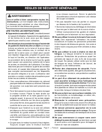
Page 3 — Français AVERTISSEMENT : Lire et veiller à bien comprendre toutes les instructions. Le non-respect des instructions ci-dessous peut entraîner un choc électrique, un incendie et des blessures graves. LIRE TOUTES LES INSTRUCTIONS Apprendre à connaître l’outil. Lire attentivement le manuel d...
Page 43 - doivent être confiés à un personnel dûment
Page 4 — Français AVERTISSEMENT : Les avertissements, autocollants et instructions contenus dans cette section du manuel concernent la sécurité. Le non-respect de toutes les instructions peut entraîner des blessures graves. Garder toutes les parties du corps à l’écart de la scie à chaîne lorsque l...
Page 44 - Toujours; APPROVISIONNEMENT EN CARBURANT; réduire les risques d’incendies et de brûlures.; REBOND; Règles de sécur ité générales; RÈGLES DE SÉCURITÉ PARTICULIÈRES
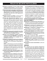
Page 5 — Français ■ Toujours maintenir la scie à deux mains lorsque le moteur tourne. La tenir fermement, les doigts et pouces encerclant les poignées. ■ Ne jamais laisser quiconque n’ayant pas reçu des instructions d’utilisation appropriées utiliser la scie. Cette règle s’applique aux scies de ...
Page 45 - SYMBOLE; Symbole d’alerte de; SYMBOLES
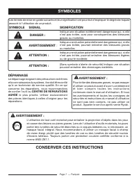
Page 6 — Français Certains des symboles ci-dessous peuvent être utilisés sur ce produit. Veiller à les étudier et à apprendre leur signification. Une interprétation correcte de ces symboles permettra d’utiliser ce produit plus efficacement et de réduire les risques. SYMBOLE NOM DÉSIGNATION / EXPLICA...
Page 46 - DÉPANNAGE; CENTRE DE RÉPARATIONS; le plus proche. Utiliser exclusivement; CONSERVER CES INSTRUCTIONS; contenues dans le manuel d’utilisation. Si tous; (Sans symbole s’alerte de sécurité) Indique une situation
Page 7 — Français DÉPANNAGE Le dépannage exigeant des précautions extrêmes et la connaissance du système, il ne doit être confié qu’à un technicien de service qualifié. En ce qui concerne les réparations, nous recommandons de confier l’outil au CENTRE DE RÉPARATIONS AGRÉÉ le plus proche. Utiliser ex...
Page 47 - Scie à chaîne sans la chaîne et le guide.; GLOSSAIRE
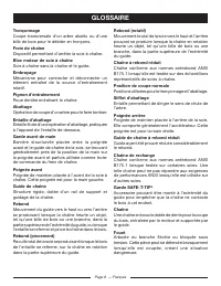
Page 8 — Français TronçonnageCoupe transversale d’un arbre abattu ou d’une bille de bois pour le débiter en tronçons.Frein de chaîneDispositif permettant d’arrêter la scie à chaîne.Bloc moteur de scie à chaîne Scie à chaîne sans la chaîne et le guide. EmbrayageMécanisme pour connecter et déconnecter...
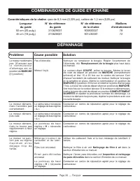
Page 48 - SPÉCIFICATIONS; Type de chaîne; CARACTÉRISTIQUES
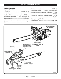
Page 9 — Français SPÉCIFICATIONS Longueur du guide : RY10520 ................................. 508 mm (20 po) RY10518 ................................. 457 mm (18 po) Pas de la chaîne ..................... 8,3 mm (0,325 po) Épaisseur de la chaîne ......... 1,27 mm (0,050 po) Type de chaîne ............
Page 49 - Voir les figures 1a et 1b.
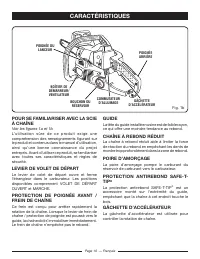
Page 10 — Français POUR SE FAMILIARISER AVEC LA SCIE À CHAÎNE Voir les figures 1a et 1b. L’utilisation sûre de ce produit exige une comprehension des renseignements figurant sur le produit et contenus dans le manuel d’utilisation, ainsi qu’une bonne connaissance du projet entrepris. Avant d’utiliser...
Page 50 - Toujours porter une protection oculaire avec; NOTE : Cette scie à chaîne a été soumise à des; DÉBALLAGE; de la boîte. S’assurer que toutes les pièces; LISTE DE CONTRÔLE D’EXPÉDITION; ASSEMBLAGE
Page 11 — Français AVERTISSEMENT : Ne pas laisser la familiarité avec ce produit faire oublier la prudence. Ne pas oublier qu’une fraction de seconde d’inattention peut entraîner des blessures graves. AVERTISSEMENT : Toujours porter une protection oculaire avec écrans latéraux certifiée conforme à l...
Page 51 - CARBURANT; Règles de sécurité; MÉLANGE DU CARBURANT; UTILISATION
Page 12 — Français AVERTISSEMENT : To u j o u r s a r r ê t e r l e m o t e u r a v a n t l’approvisionnement en carburant. Ne jamais remplir le réservoir d’une machine lorsque le moteur tourne ou est chaud. S’éloigner d’au moins 9 m (30 pi) du point d’approvisionnement avant de lancer le moteur. NE...
Page 52 - REMPLISSAGE DU RÉSERVOIR DE; NOTE : Il est normal qu’un moteur neuf dégage de; APPOINT DE LUBRIFIANT POUR GUIDE; Utiliser de lubrifiant
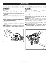
Page 13 — Français REMPLISSAGE DU RÉSERVOIR DE CARBURANT Voir la figure 2. Nettoyer le pourtour du bouchon de remplissage pour éviter la contamination du carburant. Desserrer lentement le bouchon du réservoir de carburant. Verser soigneusement le mélange de carburant d a n s l e r é s e r v o ...
Page 53 - UTILISATION DU FREIN DE CHAÎNE; Voir les figures 4 et 5.; DÉMARRAGE DU MOTEUR; Voir les figures 6 à 11.; Démarrage du moteur froid :
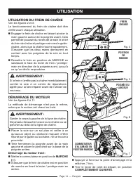
Page 14 — Français UTILISATION DU FREIN DE CHAÎNE Voir les figures 4 et 5. Le fonctionnement du frein de chaîne doit être vérifié avant chaque utilisation. Engager le frein de chaîne en faisant pivoter la main gauche autour de la poignée avant. Cela permet de pousser du revers de la main le levier...
Page 54 - NOTE : Laisser la scie tourner avec le volet de
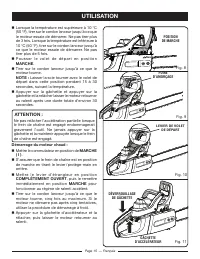
Page 15 — Français Lorsque la température est supérieure à 10 °C (50 °F), tirer sur le cordon lanceur jusqu’à ce que le moteur essaie de démarrer. Ne pas tirer plus de 3 fois. Lorsque la température est inférieure à 10 °C (50 °F), tirer sur le cordon lanceur jusqu’à ce que le moteur essaie de déma...
Page 55 - ARRÊT DU MOTEUR; D’ARRÊT; RÉGLAGE DURALENTI; « T » vers la droite pour augmenter le régime.; COMMUTATEUR
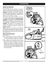
Page 16 — Français ARRÊT DU MOTEUR Voir les figures 12 et 13. Relâcher la gâchette d’accélérateur et laisser le moteur retourner au ralenti. Pour couper le moteur, mettre le commutateur d’allumage en position D’ARRÊT ( O ). Ne pas poser la scie à chaîne sur le sol si la chaîne est encore en mouvemen...
Page 56 - LA CHAÎNE NE DOIT JAMAIS TOURNER; T » vers la gauche; POUSSÉE ET TRACTION; la TRACTION lorsque la coupe est effectuée avec; TRACTION
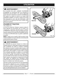
Page 17 — Français AVERTISSEMENT : LA CHAÎNE NE DOIT JAMAIS TOURNER LORSQUE LE MOTEUR EST AU RALENTI. Tourner la vis de ralenti « T » vers la gauche pour réduire le régime de ralenti et immobiliser la chaîne ou confier la scie à un centre de réparations agréé, et ne plus l’utiliser tant que les répa...
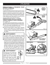
Page 57 - PRÉCAUTIONS À PRENDRE POUR; Règles de sécurité générales; NE PAS actionner la gâchette
Page 18 — Français LIGNE DE CHAÎNE PRÉCAUTIONS À PRENDRE POUR ÉVITER LE REBOND Voir les figures 16 et 17. Le rebond rotatif se produit lorsque la portion de la chaîne en mouvement se trouvant dans la zone de danger de rebond du guide heurte un objet. Il en résulte une réaction fulgurante, projetant ...
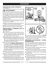
Page 58 - POSITION DE COUPE CORRECTE; DISTANCE SÉCURITAIRE de; MÉTHODES D’UTILISATION / COUPE
Page 19 — Français BRAS TENDU POUCE AU- DESSOUS DE LA POIGNÉE POSITION DE COUPE CORRECTE Voir la figure 19. AVERTISSEMENT : Toujours utiliser la position de coupe correcte décrite dans cette section. Ne jamais à genoux lorsque vous utilisez la scie à chaîne, excepté si l’abattage d’un arbre comme le...
Page 59 - NOTE : Ne jamais couper jusqu’au sifflet.; MÉTHODE CORRECTE D’ABATTAGE
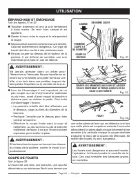
Page 20 — Français Page 21 — Français COIN n Tenir compte de la force et de la direction du vent, de l’inclinaison et de l’équilibre de l’arbre et de la position des grosses branches. Tous ces facteurs influencent la direction dans laquelle l’arbre tombera. Ne pas faire levier pour abattre un arbre ...
Page 60 - afin; procédure d’abattage correcte.; Ne couper qu’une bille à la fois.; Rebond, à la section
Page 22 — Français Page 23 — Français CHARGE COupE DE FINITION 1ÈRE COupE 1/3 DIAM BIllE SOuTENuE à uNE ExTRéMITé BIllE SOuTENuE Aux DEux ExTRéMITéS COupE DE FINITION 1ÈRE COupE 1/3 DIAMÈTRE CHARGE pour maintenir l’entaille ouverte et empêcher le pincement de la chaîne.NOTE : Lorsque des coins sont ...
Page 61 - ÉBRANCHAGE ET ÉMONDAGE; déracinée ou un arbrisseau fléchi sous tension par
Page 24 — Français ÉBRANCHAGE ET ÉMONDAGE Voir les figures 31 et 32. Travailler lentement et tenir la scie fermement à deux mains. Se tenir bien campé et en équilibre. ■ Garder le tronc entre le corps et la scie pendant la coupe. Ne pas utiliser la scie en se tenant sur une échelle. Cela est e...
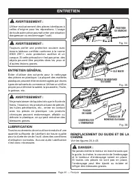
Page 62 - Utiliser exclusivement des pièces identiques à; ENTRETIEN GÉNÉRAL; types de solvants du commerce. Utiliser un chiffon; LUBRIFICATION; Tous les roulements de cet outil sont enduits d’une; REMPLACEMENT DU GUIDE ET DE LA; Si toutes ces pièces ne sont pas en place,; ENTRETIEN
Page 25 — Français AVERTISSEMENT : Utiliser exclusivement des pièces identiques à celles d’origine pour les réparations. L’usage de toute autre pièce pourrait créer une situation dangereuse ou endommager l’outil. AVERTISSEMENT : Toujours porter une protection oculaire avec écrans latéraux certifiée ...
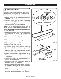
Page 63 - Toujours mettre le commutateur en position; « » avant de travailler sur la scie.; Toujours porter des gants lors de la manipulation; NOTE : Lors de l’engagement de la barre sur
Page 26 — Français RAINURE DU GUIDE MAILLONS D’ENTRAÎNEMENT DENTS MAILLONS D’ENTRAÎNEMENT AVERTISSEMENT : Pour éviter des blessures graves, lire et veiller à bien comprendre toutes les instructions de sécurité contenues dans cette section. Toujours mettre le commutateur en position D’ARRÊT, « » av...
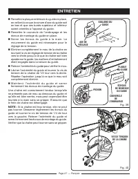
Page 64 - Serrer les écrous du guide à la main. Le
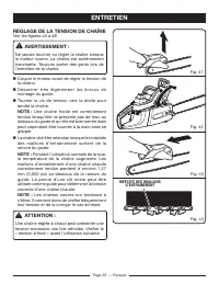
Page 27 — Français Remettre la plaque extérieure du guide en place, en veillant à ce que la rainure d’axe du guide soit en bas et que ses bords supérieur et inférieur soient orientés à l’opposé du guide. Remettre le couvercle de l’embrayage et les écrous de montage du guide en place. Serrer le...
Page 65 - RÉGLAGE DE LA TENSION DE CHAÎNE; tranchante. Toujours porter des gants lors de; NOTE : Pendant l’utilisation normale de la scie,; Une chaîne réglée à chaud peut présenter une; MÉPLATS DES MAILLONS
Page 28 — Français RÉGLAGE DE LA TENSION DE CHAÎNE Voir les figures 44 à 46. AVERTISSEMENT : Ne jamais toucher ou régler la chaîne lorsque le moteur tourne. La chaîne est extrêmement tranchante. Toujours porter des gants lors de l’entretien de la chaîne. Couper le moteur avant de régler la tension...
Page 66 - JEU DU LIMITEUR DE PROFONDEUR; ENTRETIEN DE LA CHAÎNE; position; STOP; INSPECTER
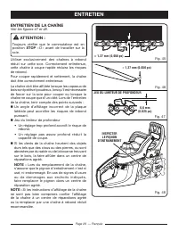
Page 29 — Français JEU DU LIMITEUR DE PROFONDEUR ≈ 1,27 mm (0,050 po) ENTRETIEN DE LA CHAÎNE Voir les figures 47 et 48. ATTENTION : Toujours vérifier que le commutateur est en position STOP « O » avant de travailler sur la scie. Utiliser exclusivement des chaînes à rebond réduit sur cette scie. Corr...
Page 67 - AFFÛTAGE DES DENTS; La chaîne est extrêmement tranchante. Toujours; Réglage de la tension de chaîne.; au point central du guide.
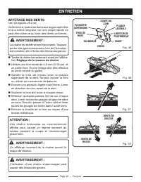
Page 30 — Français AFFÛTAGE DES DENTS Voir les figures 49 à 52. Veiller à limer toutes les dents aux angles spécifiés et à la même longueur, car une coupe rapide ne peut être obtenue qu’avec des dents uniformes. AVERTISSEMENT : La chaîne est extrêmement tranchante. Toujours porter des gants protecte...
Page 68 - ANGLE D’AFFÛTAGE DE LA PLAQUE
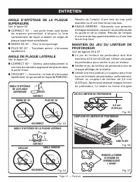
Page 31 — Français PLUS DE 30° ANGLE D’AFFÛTAGE DE LA PLAQUE SUPÉRIEURE MOINS DE 30° ANGLE ARRIÈRE ANGLE D’AFFÛTAGE DE LA PLAQUE LATÉRALE CROCHET LIME PLATE COUPLEUR DE LIMITEUR DE PROFONDEUR RENDRE LA FORME D’ORIGINE EN ARRONDISSANT L’AVANT ANGLE D’AFFÛTAGE DE LA PLAQUE SUPÉRIEURE Voir la figure 53...
Page 69 - ENTRETIEN DU GUIDE; TROU DE; E N T R E T I E N D E L A G A R D E
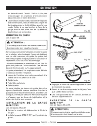
Page 32 — Français e n a r ro n d i s s a n t l ’ a v a n t . Ve i l l e r à n e p a s endommager les maillons d’entraînement adjacents avec le bord de la lime. ■ Les limiteurs de profondeur doivent être ajustés avec la lime plate, dans le sens dans lequel les dents adjacentes ont été affûtées ave...
Page 70 - NETTOYAGE DU FILTRE À AIR
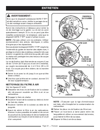
Page 33 — Français AVERTISSEMENT : Bien que le dispositif antirebond SAFE-T-TIP ® ait été installé en usine, vérifier le serrage de sa vis de montage avant chaque utilisation. Suivre les instructions ci-dessous pour serrer la vis de montage sur la garde. La vis est en acier spécialement trempé. Si l...
Page 71 - une protection oculaire.; NETTOYAGE DU LANCEUR; Nettoyer le filtre à air. Voir; FILTRE À AIR; contrôle le degré d’ouverture du papillon lorsque la
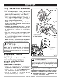
Page 34 — Français C h o i s i r l ’ u n e d e s o p t i o n s d e n e t t o y a g e suivantes : Pour nettoyer légèrement le filtre, le tapoter sur une surface plane et lisse, pour déloger la plus grande partie de la poussière et de la sciure. Toutes le 5 heures de fonctionnement, laver le filtr...
Page 72 - « T » vers la gauche,; NETTOYAGE DU MOTEUR; Voir les figures 67; AVERTISSEMENT
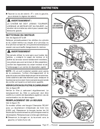
Page 35 — Français Tourner la vis de r alenti « T » vers la gauche, pour réduire le régime de ralenti. AVERTISSEMENT : LA CHAÎNE NE DOIT JAMAIS TOURNER LORSQUE LE MOTEUR EST AU RALENTI. La rotation de la chaîne au ralenti peut causer des blessures graves. NETTOYAGE DU MOTEUR Voir les figures 67 à ...
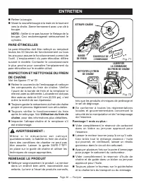
Page 73 - NOTE : Veiller à ne pas fausser le filetage de la; INSPECTION ET NETTOYAGE DU FREIN; Utilisation du frein de; REMISAGE LE PRODUIT; COUVERCLE DE; Remisage 1 mois ou plus :
Page 36 — Français Retirer la bougie. Visser la nouvelle bougie à la main en la tournant vers la droite. Serrer fermement avec une clé à bougie. NOTE : Veiller à ne pas fausser le filetage de la bougie. Ceci endommagerait sérieusement le cylindre. PARE-ÉTINCELLES Le pare-étincelles doit être net...
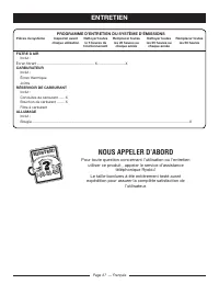
Page 74 - PROGRAMME D’ENTRETIEN DU SYSTÈME D’ÉMISSIONS; NOUS APPELER D’ABORD; Pour toute question concernant l’utilisation ou l’entretien; BESOIN D’AID
Page 37 — Français PROGRAMME D’ENTRETIEN DU SYSTÈME D’ÉMISSIONS P ièces du système Inspecter avant Nettoyer toutes Remplacer toutes Nettoyer toutes Remplacer toutes chaque utilisation le 5 heures de les 25 heures ou les 25 heures ou les 50 heures fonctionnement chaque année chaque année FILTRE À AIR...
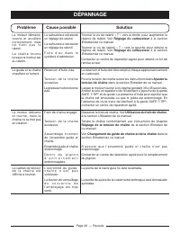
Page 75 - Problème
Page 38 — Français Problème Cause possible Solution Le moteur ne démarre pas [S’assurer que l e c o m m u t a t e u r d ’ a l l u m a g e e s t e n position de MARCHE ( l ) position.] Pas d’étincelle. Moteur noyé. Nettoyer ou remplacer la bougie. Régler l’écartement de l’électrode. Voir Remplacement...
Page 77 - GARANTIE; ÉNONCÉ DE LA GARANTIE LIMITÉE
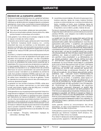
Page 40 — Français GARANTIE ÉNONCÉ DE LA GARANTIE LIMITÉE Techtronic Industries North America, Inc., garantit à l’acheteur original que ce produit RYOBI ® est exempt de tous vices de matériaux ou de fabrication et s’engage à réparer ou remplacer gratuitement, à son choix, tout produit s’avérant défe...
Page 79 - especificadas por el fabricante, o su equivalente.; REGLAS DE SEGURIDAD GENERALES
Página 3 — Español ADVERTENCIA: Lea y comprenda todas las instrucciones. El incumplimiento de las instrucciones señaladas abajo puede causar descargas eléctricas, incendios y lesiones serias. LEA TODAS LAS INSTRUCCIONES F a m i l i a r í c e s e c o n l a h e r r a m i e n t a . L e a cuidadosamen...
Page 80 - Sólo utilice la motosierra en áreas bien
Página 4 — Español Siempre traslade la motosierra con el motor apagado y el freno de la cadena puesto, la barra guía y la cadena de la sierra hacia atrás y el silenciador alejado del cuerpo. Al transportar la motosierra, use la funda correspondiente de la barra guía. No utilice la motosierra si ...
Page 81 - S i e m p re p ó n g a s e; REABASTECIMIENTO DE COMBUSTIBLE; Reglas de seguridad generales y Funcionamiento d; REGLAS DE SEGURIDAD ESPECÍFICAS
Página 5 — Español ■ Nunca permita utilizar la sierra a quien no haya recibido instrucciones adecuadas sobre la forma correcta de emplear la unidad. Esto se aplica tanto a las sierras alquiladas como a las propias. ■ Antes de arrancar el motor, asegúrese de que no esté tocando ningún objeto la c...
Page 82 - SÍMBOLO; SÍMBOLOS
Página 6 — Español Es posible que se empleen en este producto algunos de los siguientes símbolos. Le suplicamos estudiarlos y aprender su significado. Una correcta interpretación de estos símbolos le permitirá utilizar mejor y de manera más segura la producto. SÍMBOLO NOMBRE DENOMINACIÓN / EXPLICACI...
Page 83 - SERVICIO; CENTRO DE SERVICIO; GUARDE ESTAS INSTRUCCIONES; operador. Si no comprende los avisos de; (Sin el símbolo de alerta de seguridad.) Indica una situación
Página 7 — Español SERVICIO El servicio de la herramienta requiere extremo cuidado y conocimientos técnicos, por lo cual sólo debe ser efectuado por un técnico de servicio calificado. Para dar servicio a la herramienta, le sugerimos llevarla al CENTRO DE SERVICIO AUTORIZADO de su preferencia para qu...
Page 84 - al nivel de contragolpe estipulados en la norma ANSI; de la punta; GLOSARIO DE TÉRMINOS
Página 8 — Español TronzadoEs el proceso de cortar transversalmente un árbol o tronco talado en tramos.Freno de la cadenaEs un dispositivo empleado para detener la cadena de la sierra.Cabeza motriz de la motosierraEs la motosierra sin la cadena de aserrar ni la barra guía.EmbragueEs un mecanismo par...
Page 85 - ESPECIFICACIONES DEL PRODUCTO; Longitud de la barra:; CARACTERÍSTICAS
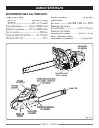
Página 9 — Español ESPECIFICACIONES DEL PRODUCTO Longitud de la barra: RY10520 ............................. 508 mm (20 pulg.) RY10518 ............................. 457 mm (18 pulg.) Paso de la cadena .............. 8,3 mm (0,325 pulg.) Calibre de la cadena......... 1,27 mm (0,050 pulg.) Tipo de cad...
Page 86 - Vea las figuras 1a y 1b.
Página 10 — Español FAMILIARÍCESE CON LA MOTOSIERRA Vea las figuras 1a y 1b. Para usar este producto con la debida seguridad se debe comprender la información indicada en la producto misma y en este manual, y se debe comprender también el trabajo que intenta realizar. Antes de usar este producto, fa...
Page 87 - No permita que su familarización con este; N O TA : L a m o t o s i e r r a h a s i d o p r o b a d a; DESEMPAQUETADO; Extraiga cuidadosamente de la caja la producto; LISTA DE EMPAQUETADO; Eliminación de raíces zancas; ARMADO
Página 11 — Español ADVERTENCIA: No permita que su familarización con este producto lo vuelva descuidado. Tenga presente que un descuido de un instante es suficiente para causar una lesión grave. ADVERTENCIA: Siempre póngase protección ocular con la marca de cumplimiento de la norma ANSI Z87.1 junto...
Page 88 - COMBUSTIBLE Y REABASTECIMIENTO; Reabastecimiento de; Reglas de seguridad; de este manual, donde encontrará; MEZCLADO DEL COMBUSTIBLE; GASOLINA; COMBUSTIBLES OXIGENADOS; NO USE COMBUSTIBLE E85. ANULARÁ SU
Página 12 — Español ADVERTENCIA: Siempre apague el motor antes de abastecer e l c o m b u s t i b l e . N u n c a re a b a s t e z c a d e combustible ninguna máquina con el motor en marcha o caliente. Aléjese por lo menos 9 metros (30 pies) del sitio de reabastecimiento de combustible antes de ence...
Page 89 - LLENADO DEL TANQUE; NOTA: Es normal la emisión de humo en los; ABASTECIMIENTO DE LUBRICANTE
Página 13 — Español LLENADO DEL TANQUE Vea la figura 2. Limpie la superficie situada alrededor de la tapa del combustible para evitar la contaminación del mismo. A f l o j e l e n t a m e n t e l a t a p a d e l t a n q u e d e combustible. Cuidadosamente vierta en el tanque la mezcla de combu...
Page 90 - FUNCIONAMIENTO DEL FRENO DE LA; Vea las figuras 4 y 5.; ARRANQUE DEL MOTOR; Vea las figuras 6 a 11.; Para arrancar con el motor frío:
Página 14 — Español FUNCIONAMIENTO DEL FRENO DE LA CADENA Vea las figuras 4 y 5. Verifique las condiciones de funcionamiento del freno de la cadena cada vez antes de usar la unidad. Accione el freno de la cadena rotando su mano izquierda alrededor del mango frontal, de manera tal que permita que l...
Page 91 - completamente hacia afuera, a la posición de; ANEGACIÓN MÁXIMA; empiece a funcionar el motor.; NOTA: Permita que la sierra funcione en esta; Presione el liberador del gatillo y oprima y suelte; Para arrancar con el motor caliente:; a l a p o s i c i ó n; A N E G A C I Ó N M Á X I M A
Página 15 — Español Asegúrese de que el freno de la cadena esté en la posición de funcionamiento; para ello, tire de la palanca (la protección de la mano) hacia atrás. Oprima hasta el fondo y suelte la bomba de cebado siete veces. Tire de la palanca del anegador del carburador completamente ha...
Page 92 - FUNCIONAMIENTO para un arranque; empiece a funcionar el motor, pero no lo haga; APAGADO DEL MOTOR; AJUSTE DE LA MARCHA LENTA; “T” hacia la derecha para aumentar; la velocidad de dicha marcha.; “T” hacia
Página 16 — Español i n m e d i a t a m e n t e d e s p u é s , e m p ú j e l a a l a posición FUNCIONAMIENTO para un arranque en frío. Tire del mango del arrancador hasta que empiece a funcionar el motor, pero no lo haga más de 5 veces. Si el motor no arranca luego de 5 intentos, recurra al proce...
Page 93 - efectúe la reparación. Si la cadena se mueve al; EMPUJÓN Y TIRÓN; por el borde superior de dicha barra.; TIRÓN; El
Página 17 — Español ADVERTENCIA: LA CADENA DE LA SIERRA NUNCA DEBE AVANZAR AL ESTAR EL MOTOR EN MARCHA LENTA. Gire el tornillo de marcha lenta “T” hacia la izquierda para reducir dicha marcha y así detener la cadena, lleve la unidad un centro de servicio autorizado para que la ajusten y suspenda el ...
Page 94 - PRECAUCIONES RELACIONADAS CON; Consulte el apartado
Página 18 — Español PRECAUCIONES RELACIONADAS CON EL CONTRAGOLPE Vea las figuras 16 y 17. El contragolpe rotatorio ocurre cuando la cadena en movimiento hace contacto con un objeto en la zona de peligro de contragolpe de la barra guía. El resultado es una reacción súbita en dirección inversa, la cua...
Page 95 - POSTURA CORRECTA PARA EL CORTE; DI S TA NCI A S E GUR A de l á re a de c or t e .; PROCEDIMIENTOS BÁSICOS DE
Página 19 — Español EL BRAZO RECTO EL PULGAR BAJO LA BARRA DEL MANGO PLANO DE LA CADENA ADVERTENCIA: NO accione el gatillo del acelerador con la mano i z q u i e rd a , s u j e t a n d o e l mango delantero con la m a n o d e r e c h a . N u n c a permita que ninguna parte del cuerpo cruce el plano ...
Page 96 - Mantenga el motor a la máxima aceleración; TALA DE ÁRBOLES; Si el árbol comienza a caer en una dirección; PROCEDIMIENTO CORRECTO PARA
Página 20 — Español al manejo de la sierra antes de comenzar una tarea de corte de mayores proporciones. Adopte una postura correcta del cuerpo frente a la madera, con la sierra en marcha lenta. Acelere el motor hasta el punto máximo justo antes de comenzar el corte; para ello, oprima el gatillo...
Page 97 - segura aproximadamente a 135o de la línea; NOTA: Al tronzar o talar un árbol con una cuña,; ELIMINACIÓN DE RAÍCES ZANCAS
Página 21 — Español CUÑA CORTE HORIZONTAL CORTE VERTICAL PARTE SUELTA de retirada. Despeje la trayectoria de retirada segura aproximadamente a 135º de la línea planeada de caída del árbol. Considere la fuerza y dirección del viento, la inclinación y equilibrio del árbol, y por último, la ubicación...
Page 98 - CUÑA; Procedimiento correcto para; TRONZADO; Tronzado es el término aplicado al corte del tronco; Contragolpe de; Reglas de seguridad específicas; TRONZADO CON CUÑA; Si el diámetro del tronco es suficientemente
Página 22 — Español CUÑA CONTRAGOLPE ARMADO raíz zanca, seguido del corte vertical. Retire del área de trabajo la parte suelta resultante. Una vez habiendo eliminado las raíces zancas grandes de la forma señalada en Procedimiento correcto para talar árboles, aplique el procedimiento adecuado para ta...
Page 99 - T R O N Z A D O D E T R O N C O S B A J O; Efectúe el primer corte de tronzado a 1/3 del; TRONZADO POR ARRIBA
Página 23 — Español TRONZADO POR ARRIBA CARGA CORTE FINAL PRIMER CORTE, 1/3 DEL DIÁM. TRONCO APOYADO POR UN EXTREMO TRONCO APOYADO POR AMBOS EXTREMOS CORTE FINAL PRIMER CORTE, 1/3 DEL DIÁM. CARGA ARMADO TRONZADO POR ABAJO T R O N Z A D O D E T R O N C O S B A J O TENSIÓN Vea la figura 28. Efectúe el...
Page 100 - DESRAMADO Y PODA
Página 24 — Español CORTE FINAL SEGUNDO CORTE CARGA PÉRTIGA CORTE UNA RAMA A LA VEZ Y DEJE RAMAS DE SOPORTE BAJO EL ÁRBOL HASTA QUE ESTÉ CORTADO EL TRONCO ARMADO DESRAMADO Y PODA Vea las figuras 31 y 32. Trabaje lentamente, manteniendo ambas manos en la sierra, sujetándola firmemente. Mantenga bie...
Page 101 - MANTENIMIENTO; MANTENIMIENTO GENERAL; Todos los cojinetes de esta herramienta están; CÓMO REEMPLAZAR LA BARRA GUÍA; tambor del embrague. Sin todas estas piezas en
Página 25 — Español POSICIÓN DE FUNCIONAMIENTO MANTENIMIENTO TUERCAS DE MONTAJE DE LA BARRA LLAVE COMBINACIÓN TAPA DEL EMBRAGUE PLACA DE LA BARRA GUÍA TUERCAS DE MONTAJE DE LA BARRA ADVERTENCIA: Al dar servicio a la unidad, sólo utilice piezas de repuesto idénticas. El empleo de piezas diferentes pu...
Page 102 - Siempre coloque; APAGADO ( ) antes de realizar cualquier; de la cadena. Si están orientados en la dirección; NOTA: Al colocar la barra en los per nos,
Página 26 — Español RANURA DE LA BARRA ESLABONES DE IMPULSIÓN DE LA CADENA MANTENIMIENTO ADVERTENCIA: Para evitar lesiones corporales serias, lea y comprenda todas las instrucciones de seguridad indicadas en esta sección. Siempre coloque el interruptor en la posición de APAGADO ( ) antes de realiz...
Page 103 - Suelte la punta de la barra guía y gire 1/2
Página 27 — Español MANTENIMIENTO PASADOR DE AJUSTE PERNOS DE MONTAJE DE LA BARRA PLACA DE LA BARRA GUÍA TAPA DEL EMBRAGUE RUEDA DENTADA TUERCAS DE MONTAJE DE LA BARRA TORNILLO DE TENSADO DE LA CADENA Vuelva a montar la placa exterior de la barra guía, asegurándose de que la ranura del pasador de ...
Page 104 - PARTES PLANAS DE LOS; AJUSTE DE LA TENSIÓN DE LA; está sumamente afilada. Siempre lleve puestos; NOTA: Durante el funcionamiento normal de la; sierra, aumenta la temperatura de la sierra. Si la; NOTA: Las cadenas nuevas tienden a estirarse; Si se tensa la cadena estando ésta caliente,
Página 28 — Español MANTENIMIENTO PARTES PLANAS DE LOS ESLABONES DE IMPULSIÓN AJUSTE DE LA TENSIÓN DE LA CADENA Vea las figuras 44 a 46. ADVERTENCIA: Nunca toque ni ajuste la cadena mientras esté funcionando el motor. La cadena de la sierra está sumamente afilada. Siempre lleve puestos guantes prote...
Page 105 - INSPECCIONE; MANTENIMIENTO DE LA CADENA; APAGADO “ O ” antes de realizar cualquier; la capacidad de corte.; NOTA: Al cambiar la cadena, inspeccione la; rueda dentada de impulsión para ver si tiene
Página 29 — Español MANTENIMIENTO ≈ 1,27 mm (0,050 pulg.) 0,6 mm (0,025 pulg.) ≈ 1,27 mm (0,050 pulg.) INSPECCIONE LA RUEDA DENTADA DE IMPULSIÓN ESPACIO LIBRE DE LOS DIENTES LIMPIADORES (CALIBRES DE PROFUNDIDAD) MANTENIMIENTO DE LA CADENA Vea las figuras 47 y 48. PRECAUCIÓN: Verifique que el interru...
Page 106 - AFILADO DE LOS DIENTES DE CORTE; Tenga cuidado de afilar todos los dientes de corte; Ajuste de la tensión de la cadena.; Mantenga la lima al nivel de la placa superior
Página 30 — Español MANTENIMIENTO ESQUINA DE CORTE PLACA LATERAL CALIBRE DE PROFUNDIDAD PUNTERA GARGANTA TALÓN ORIFICIO DEL REMACHE PLACA SUPERIOR DIENTES DE CORTE IZQUIERDOS DIENTES DE CORTE DERECHOS AFILADO DE LOS DIENTES DE CORTE Vea las figuras 49 a 52. Tenga cuidado de afilar todos los dientes ...
Page 107 - ÁNGULO DE LIMADURA DE LA PLACA
Página 31 — Español FORMA INCORRECTA MÁS DE 30° ÁNGULO DE LIMADURA DE LA PLACA SUPERIOR MENOS DE 30° FORMA CORRECTA FORMA INCORRECTA PENDIENTE HACIA ATRÁS ÁNGULO DE LIMADURA DE LA PLACA LATERAL FORMA CORRECTA GANCHO LIMA PLANA IGUALADOR DE CALIBRES DE PROFUNDIDAD RESTABLEZCA LA FORMA ORIGINAL REDOND...
Page 108 - Tenga cuidado de no dañar los eslabones de; MANTENIMIENTO DE LA BARRA GUÍA; desgaste de la misma. Tales fallas deben alisarse; MONTAJE DE LA PROTECCIÓN SAFE-
Página 32 — Español ORIFICIO DE LUBRICACIÓN TORNILLO DE MONTAJE APRIÉTELO 3/4 DE VUELTA MANTENIMIENTO de profundidad, devuélvales su forma original redondeando la parte frontal de los mismos. Tenga cuidado de no dañar los eslabones de impulsión adyacentes con el borde de la lima. ■ Cada calibre de...
Page 109 - endurecidos. Si no puede apretarse el tornillo,; LIMPIEZA DEL FILTRO DE AIRE; NOTA: Asegúrese de que la barra del anegador
Página 33 — Español TORNILLO TORNILLO DE RETENCIÓN DEL FILTRO DE AIRE FILTRO DE AIRE TAPA DEL CILINDRO PREFILTRO UNIDAD DEL ARRANCADOR DEFLECTOR DEL ALOJAMIENTO DEL VENTILADOR TORNILLOS MANTENIMIENTO ADVERTENCIA: Aunque la barra guía viene con una protección anticontragolpe SAFE-T-TIP ® ya montada, ...
Page 110 - Ajuste de marcha lenta — El ajuste de marcha; con uno nuevo después de cada 25 horas de uso.; NOTA: Un método alternativo es limpiar el; filtro con aire comprimido. Siempre póngase; L I M P I E Z A D E L A U N I D A D D E L; Antes de ajustar el carburador:; Mantenimiento
Página 34 — Español FILTRO DE AIRE RESPIRADEROS DE LA TAPA DEL ARRANCADOR TORNILLO DE MARCHA LENTA “T” MANTENIMIENTO ADVERTENCIA: Las condiciones del tiempo y la altitud pueden afectar la carburación. No permita la presencia de personas cerca de la motosierra mientras ajusta el carburador. Ajuste de...
Page 111 - “T” si desea disminuir la misma.; LA CADENA DE LA SIERRA NUNCA DEBE; LIMPIEZA DEL MOTOR; Si observa alguna pérdida de potencia en; REVISIÓN DEL FILTRO DE COMBUSTIBLE; Revise periódicamente el filtro de combustible. Si el; CAMBIO DE LA BUJÍA
Página 35 — Español LIMPIE LAS ALETAS DEL CILINDRO LIMPIE LAS ALETAS DEL VOLANTE FILTRO DE COMBUSTIBLE MANTENIMIENTO Gire a la izquierda el tornillo de marcha lenta “T” si desea disminuir la misma. ADVERTENCIA: LA CADENA DE LA SIERRA NUNCA DEBE AVANZAR AL ESTAR EL MOTOR EN MARCHA LENTA. Si la cade...
Page 112 - Tenga cuidado de no estropear la rosca; PARACHISPAS; cada 50 horas o anualmente para asegurarse; INSPECCIÓN Y LIMPIEZA DEL FRENO; Siempre mantenga el mecanismo del freno; Funcionamiento; ALMACENAMIENTO DE LA PRODUCTO; Al almacenar 1 mes o más:
Página 36 — Español BANDA DEL FRENO LIMPIE EL FRENO DE LA CADENA LUBRIQUE LA ARTICULACIÓN DEL FRENO DE LA CADENA SOSTÉN DE LA CADENA TAPA DEL EMBRAGUE MANTENIMIENTO Enrosque la nueva bujía con la mano, girándola hacia la derecha. Apriétela firmemente con una llave. NOTA: Tenga cuidado de no estrop...
Page 113 - LLÁMENOS PRIMERO; ¿NECESITA A
Página 37 — Español MANTENIMIENTO PROGRAMA DE MANTENIMIENTO PARA EL CONTROL DE EMISIONES Pieza s para el Inspeccionar cada vez Limpiar cada Reemplazar cada Limpiar cada Reemplazar cada control de antes de usar la unidad 5 horas de uso 25 horas de uso 25 horas de uso 50 Horas emisiones o cada año o c...
Page 114 - Problema; F U N C I O N A M I E N T O; SOLUCIÓN DE PROBLEMAS
Página 38 — Español Problema Causa posible Solución E l m o t o r n o a r r a n c a . [Asegúrese de que el interruptor de encendido esté en la posición de F U N C I O N A M I E N T O ( l ).] No hay chispa. Está ahogado el motor. Limpie o reemplace la bujía, según sea necesario. Reajuste la separació...
Page 116 - GARANTÍA; DECLARACIÓN DE LA GARANTÍA LIMITADA
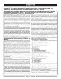
Página 40 — Español GARANTÍA DECLARACIÓN DE LA GARANTÍA LIMITADA Techtronic Industries North America, Inc. garantiza al comprador original al menudeo que este producto de la marca RYOBI ® carece de defectos en los materiales y en la mano de obra, y acuerda reparar o remplazar, a la sola discreción d...
Page 118 - OPERATOR’S MANUAL; TECHTRONIC INDUSTRIES NORTH AMERICA, INC.
RY10520 / 20 in. 46cc Chain Saw Scie à chaîne de 46 cc de 508 mm (20 po) Motosierra de 508 mm (20 pulg.), 46 cc RY10518 / 18 in. 46cc Chain Saw Scie à chaîne de 46 cc de 457 mm (18 po) Motosierra de 457 mm (18 pulg.), 46 cc (ALL VERSIONS) (TOUTES LES VERSIONS) (TODAS LAS VERSIONES) OPERATOR’S MANUAL...


 Ryobi SS630
User Manual
Ryobi SS630
User Manual
 Ryobi 18A-C06-734
User Manual
Ryobi 18A-C06-734
User Manual
 Ryobi 21AB454B734
User Manual
Ryobi 21AB454B734
User Manual
 Ryobi 41CD875A034
User Manual
Ryobi 41CD875A034
User Manual
 Ryobi 767R
User Manual
Ryobi 767R
User Manual
 Ryobi 2079R
User Manual
Ryobi 2079R
User Manual
 Ryobi 725R
User Manual
Ryobi 725R
User Manual
 Ryobi 890R
User Manual
Ryobi 890R
User Manual
 Ryobi 825R
User Manual
Ryobi 825R
User Manual
 Ryobi 96116000202
User Manual
Ryobi 96116000202
User Manual