Page 2 - GENERAL POWER TOOL SAFETY WARNINGS; Save all warnings and instructions for future reference.; WORK AREA SAFETY; Keep work area clean and well lit.; ELECTRICAL SAFETY; Do not expose power tools to rain or wet conditions.; PERSONAL SAFETY; Do not wear loose clothing or jewelry.; POWER TOOL USE AND CARE
2 - English GENERAL POWER TOOL SAFETY WARNINGS WARNING: Read all safety warnings, instructions, illustrations and specifications provided with this power tool. Failure to follow all instructions listed below may result in electric shock, fire and/or serious injury. Save all warnings and instructions...
Page 3 - have the power tool repaired before use.; BATTERY TOOL USE AND CARE; connection from one terminal to another.; SERVICE; Never service damaged battery packs.; CUTTING PROCEDURES; Do not reach underneath the workpiece.
3 - English GENERAL POWER TOOL SAFETY WARNINGS TRACK SAW SAFETY WARNINGS have the power tool repaired before use. Many ac- cidents are caused by poorly maintained power tools. Keep cutting tools sharp and clean. Properly maintained cutting tools with sharp cutting edges are less likely to bind and...
Page 4 - Do not use dull or damaged blades.; GUARD FUNCTION; Do not use abrasive wheels with this saw.; RIVING KNIFE FUNCTION; Use the appropriate saw blade for the riving knife.; TRACK SAW SAFETY WARNINGS
4 - English KICKBACK CAUSES AND RELATED WARNINGS Kickback is a sudden reaction to a pinched, jammed or misaligned saw blade, causing an uncontrolled saw to lift up and out of the workpiece toward the operator; When the blade is pinched or jammed tightly by the kerf closing down, the blade stalls...
Page 5 - NOTICE; SYMBOLS
5 - English The following signal words and meanings are intended to explain the levels of risk associated with this product. SYMBOL SIGNAL MEANING DANGER: Indicates a hazardous situation, which, if not avoided, will result in death or serious injury. WARNING: Indicates a hazardous situation, which, ...
Page 6 - INSTALLING THE BLADE; FEATURES; PRODUCT SPECIFICATIONS; ASSEMBLY; UNPACKING
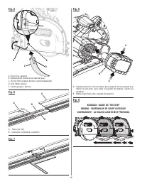
6 - English WARNING: Do not attempt to modify this product or create acces-sories not recommended for use with this product. Any such alteration or modification is misuse and could result in a hazardous condition leading to possible serious personal injury. WARNING: To prevent accidental starting th...
Page 7 - REMOVING THE BLADE; do not remove
7 - English ASSEMBLY Slowly allow the front handle to rise until the saw locks in the blade change position. In this position, the saw cannot be lowered or raised. Place the saw on its side with the spindle facing up. Depress and hold the spindle lock button and remove the blade screw and oute...
Page 8 - OPERATION; APPLICATIONS; ASSEMBLING TRACKS
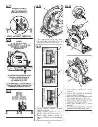
8 - English OPERATION WARNING: Do not allow familiarity with products to make you care-less. Remember that a careless fraction of a second is sufficient to inflict serious injury. WARNING: Always remove battery pack from the tool when you are assembling parts, making adjustments, cleaning, or when n...
Page 9 - KICKBACK; PLUNGE DEPTH CONTROL LEVER; Blade change position; ATTACHING THE SAW TO A VACUUM
9 - English KICKBACK See Figures 9 - 13, pages 19 - 20. Kickback occurs when the blade stalls rapidly and the saw is driven back towards you. Blade stalling is caused by any action which pinches the blade in the wood. DANGER: Release switch immediately if blade binds or saw stalls. Kickback could ca...
Page 10 - To raise the cutting blade:; USING THE DEPTH LOCK KNOB; Do not remove the saw from the; USING THE TRACK; To trim the rubber cut strip on the tracks:
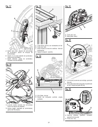
10 - English OPERATION To raise the cutting blade: Slowly allow the front handle to rise until the blade and riving knife (if installed) are completely inside of the guard and the saw is in the locked position. USING THE DEPTH LOCK KNOB See Figure 17, page 21. Always keep correct blade depth setti...
Page 11 - To make cuts along the track:; OPERATING THE SAW; NEVER; CROSS CUTTING/RIP CUTTING
11 - English right) is eliminated and the saw moves freely (forward and back). Tighten the lock knobs. Place the plunge depth control lever in the scoring posi- tion. Reinstall the battery pack. Slide the saw to the starting end track and ensure the blade is positioned to cut all the rubber. ...
Page 12 - RIP CUTTING ALONG A TRACK; BEVEL CUTTING
12 - English OPERATION Inspect the wood before making any cuts. There should be no nails or foreign objects in the workpiece.When making a cross cut or rip cut along a track, align the line of cut with the rubber cut strip on the track. RIP CUTTING ALONG A TRACK Remove the battery pack and install...
Page 13 - EXTENDED BEVEL SETTINGS
13 - English OPERATION NOTE: To remove the saw from the track, loosen the anti-tip knob and swing it outwards to retract the lock plate and pull the saw up and away from the track. Loosen the bevel lock knobs and move the saw to the desired bevel angle. Bevel angles can be set from -1° to 48°. N...
Page 14 - POCKET CUTTING; ADJUSTMENTS
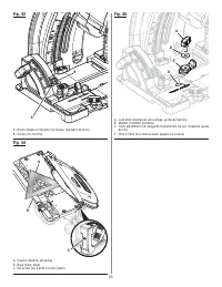
14 - English WARNING: To prevent accidental starting that could cause serious personal injury, always remove the battery pack from the product when making adjustments. ADJUSTING THE BASE PARALLEL TO THE TO THE BLADE See Figures 40 - 41, page 24. Remove battery pack. Place the saw in an upside do...
Page 15 - If the distances are different:; TO SET THE BLADE AT 0° AND 45°; If the blade is not an exact 45°:
15 - English ADJUSTMENTS If the distances are different: Remove battery pack. Remove the screw near the center of the base, washer, compression spring and cone. Place the plunge depth control lever in the plunge cut position. Lower the blade completely. Turn the saw upside down. Loosen b...
Page 16 - GENERAL MAINTENANCE; MAINTENANCE; REPLACING THE TRACK ADJUSTMENT TAB; ACCESSORIES
16 - English NOTE: ILLUSTRATIONS START ON PAGE 17 AFTER FRENCH AND SPANISH LANGUAGE SECTIONS. WARNING: When servicing, use only identical replacement parts. Use of any other parts may create a hazard or cause product damage. WARNING: Always wear eye protection with side shields marked to comply with...
Page 17 - AVERTISSEMENT; AVERTISSEMENTS DE SÉCURITÉ
2 – Français AVERTISSEMENT Lire les avertissements de sécurité, les instructions et les précisions et consulter les illustrations fournis avec cet outil électrique. Le fait de ne pas se conformer à l’ensemble des consignes présentées ci-dessous risque d’entraîner des décharges électriques, un incend...
Page 18 - MÉTHODE DE COUPE; AVERTISSEMENTS DE SÉCURITÉ GENERALES
3 – Français MÉTHODE DE COUPE DANGER : Garder les mains à l’écart de la zone de coupe et de la lame. Garder la deuxième main sur la poignée auxiliaire ou le boîtier du moteur. Lorsque les mains sont utilisées pour tenir la scie, elle ne risquent pas d’être coupées par la lame. Ne pas passer les ma...
Page 19 - FONCTION DE GARDE; FONCTION DE COUTEAU DIVISEUR
4 – Français CAUSES DES EFFETS DE REBOND ET AUTRES AVERTISSEMENTS Le rebond est une réaction soudaine, causée par une lame coincée, bloquée ou mal alignée et projetant la scie hors de la pièce coupée vers le haut, en direction de l’opérateur; Lorsque la lame est pincée ou bloquée par la fermetur...
Page 20 - SYMBOLES; SYMBOLE
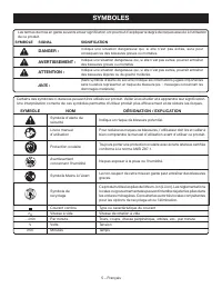
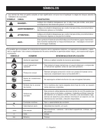
5 – Français Certains des symboles ci-dessous peuvent être utilisés sur produit. Veiller à les étudier et à apprendre leur signification. Une interprétation correcte de ces symboles permettra d’utiliser produit plus efficacement et de réduire les risques. SYMBOLE NOM DÉSIGNATION / EXPLICATION Symbol...
Page 21 - INSTALLATION DE LA LAME; CARACTÉRISTIQUES; FICHE TECHNIQUE; ASSEMBLAGE; DÉBALLAGE
6 – Français AVERTISSEMENT : Ne pas essayer de modifier cet produit ou de créer des accessoires non recommandés pour l’produit. De telles altérations ou modifications sont considérées comme un usage abusif et peuvent créer des conditions dangereuses, risquant d’entraîner des blessures graves. AVERTI...
Page 22 - RETRAIT DE LA LAME
7 – Français ASSEMBLAGE Dans cette position, la scie ne peut pas être abaissée ou levée. Placer la scie sur son côté en orientant la broche vers le haut. Appuyer et tenir sur le bouton de verrouillage de l’axe et retire le vis de lame et rondelle de lame extérieure. NOTE : Tourner le boulon de l...
Page 23 - UTILISATION; ASSEMBLAGE DES RAILS
8 – Français UTILISATION AVERTISSEMENT : Ne pas laisser la familiarité avec l’produit faire oublier la prudence. Ne pas oublier qu’une fraction de seconde d’inattention peuvant entraîner des blessures graves. AVERTISSEMENT : Toujours retirer la bloc-pile de l’outil au moment d’assembler des pièces, ...
Page 25 - LAMES DE SCIE
10 – Français UTILISATION UTILISATION DU BOUTON DE VERROUILLAGE DE LA PROFONDEUR Voir la figure 17, page 21. Toujours maintenir un réglage de profondeur de coupe correct. Quelle que soit le type de coupe, la lame ne doit pas dépasser de plus de 6,4 mm (1/4 po) au-dessous de la pièce coupée. Un dépas...
Page 26 - UTILISATION DE LA SCIE; COUPE TRANSVERSALE ET REFENTE
11 – Français Placer le levier de contrôle de la profondeur de plongée dans la position d’entaille. Réinstaller le bloc-piles. Glisser la scie jusqu’au rail d’extrémité du début et vérifier que la lame est positionnée pour couper tout le caoutchouc. Démarrer la scie et la laisser atteindre s...
Page 27 - COUPE EN BISEAU
12 – Français UTILISATION Inspecter le bois avant d’effectuer une coupe. Il ne devrait pas y avoir de clous ou d’objets étrangers dans la pièce à travailler. Il ne devrait pas y avoir de clous ou d’objets étrangers dans la pièce à travailler.Pour effectuer une coupe transversale ou longitudinale le ...
Page 28 - RÉGLAGES DU BISEAU PROLONGÉ
13 – Français UTILISATION Tenir la scie en angle et guider la plaque de verrouillage sous le rebord du rail. Placer le reste de la scie sur le rail et ajuster au besoin. NOTE : Pour retirer la scie du rail, desserrer le bouton antibascule et le basculer vers l’extérieur pour rétracter la plaque ...
Page 29 - ÉVIDEMENTS; RÉGLAGES
14 – Français AVERTISSEMENT : Pour empêcher un démarrage accidentel pouvant entraîner des blessures graves, tojours retirer le bloc de bloc-pile de l’produit avant d’assembler des pièces. AJUSTEMENT DE LA BASE PARALLÈLEMENT À LA LAME Voir les figures 40 et 41, page 24. Retirer le bloc-piles. Pla...
Page 30 - RÉGLAGE DE LA LAME À 0 ET 45°
15 – Français RÉGLAGES Si les distances mesurées sont différentes : Retirer le bloc-piles. Retirer la vis près du centre de la base, la rondelle, le ressort de compression et le cône. Placer le levier de contrôle de la profondeur de plongée dans la position de coupe en plongée. Abaisser comp...
Page 31 - ENTRETIEN GÉNÉRAL; ENTRETIEN; ACCESSOIRES
16 – Français NOTE: ILLUSTRATIONS COMMENCE À LA PAGE 17 APRÈS LES SECTION EN ESPAGNOL. AVERTISSEMENT : Utiliser exclusivement des pièces d’origine pour les répara-tions. L’usage de toute autre pièce pourrait créer une situa-tion dangereuse ou endommager l’outil. AVERTISSEMENT : Always wear eye prote...
Page 32 - SEGURIDAD EN EL ÁREA DE TRABAJO; SEGURIDAD ELÉCTRICA; ADVERTENCIAS DE SEGURIDAD; EMPLEO Y CUIDADO DE LA HERRAMIENTA
2 – Español ADVERTENCIA: Lea todas las advertencias, instrucciones, ilustraciones y especificaciones proporcionadas con esta herramienta eléctrica. No seguir las instrucciones indicadas a continuación puede provocar descargas eléctricas, incendios o lesiones graves. Guarde todas las advertencias e i...
Page 33 - ADVERTENCIAS DE SEGURIDAD SIERRA DE RIEL; PROCEDIMIENTOS DE CORTE; SERVICIO
3 – Español ADVERTENCIAS DE SEGURIDAD SIERRA DE RIEL PROCEDIMIENTOS DE CORTE PELIGRO: Mantenga las manos alejadas del área de corte y de la hoja. Mantenga la otra mano en el mango auxiliar o en el alojamiento del motor. Si ambas manos están sujetando la sierra, la hoja de corte no puede lesionarlas....
Page 34 - FUNCIÓN DE PROTECCIÓN; FUNCIÓN DE LA CUCHILLA SEPARADORA
4 – Español CAUSAS DE CONTRAGOLPE Y ADVERTENCIAS RELACIONADAS El contragolpe es una reacción súbita a un pellizcamiento, atoramiento o desalineación de la hoja de la sierra, lo cual causa el descontrol, levantamiento y salida de la misma de la pieza de trabajo, hacia el operador. Cuando el corte...
Page 35 - SÍMBOLOS; SÍMBOLO
5 – Español SÍMBOLOS Es posible que se empleen en este producto algunos de los siguientes símbolos. Le suplicamos estudiarlos y apren- der su significado. Una correcta interpretación de estos símbolos le permitirá utilizar mejor y de manera más segura el producto. SÍMBOLO NOMBRE DENOMINACIÓN/EXPLICA...
Page 36 - INSTALACIÓN DE LA HOJA; CARACTERÍSTICAS; ESPECIFICACIONES DEL PRODUCTO; ARMADO; DESEMPAQUETADO
6 – Español ADVERTENCIA: No intente modificar este producto ni hacer accesorios no recomendados para la misma. Cualquier alteración o modificación constituye maltrato el cual puede causar una condición peligrosa, y como consecuencia posibles lesiones corporales serias. ADVERTENCIA: Para evitar un ar...
Page 37 - EXTRACCIÓN DE LA HOJA
7 – Español ARMADO Recueste la sierra sobre un lado con el husillo orientado hacia arriba. Presione y mantenga el botón de seguridad del husillo y extraiga el tornillo de la hoja y arandela exterior de la hoja NOTA: Gire el tornillo de la hoja hacia la izquierda para retirarlo. AVISO: Para evita...
Page 38 - FUNCIONAMIENTO; APLICACIONES; MONTAJE DE LOS RIELES
8 – Español FUNCIONAMIENTO ADVERTENCIA: No permita que su familarización con los productos lo vuelva descuidado. Tenga presente que un descuido de un instante es suficiente para causar una lesión grave. ADVERTENCIA: Siempre retire el paquete de baterías de la herramienta cuando esté ensamblando part...
Page 39 - CONTRAGOLPE; PALANCA DE CONTROL DE PROFUNDIDAD
9 – Español CONTRAGOLPE Vea las figuras 9 a 13, páginas 19 - 20. El contragolpe sucede cuando la hoja se detiene rápidamente y la sierra sale empujada hacia el operador. El atoramiento de la hoja es causado por cualquier acción que produzca el pellizcamiento de la hoja en la madera. PELIGRO: Si la h...
Page 40 - HOJAS DE SIERRA; BOTÓN DEL SEGURO DE APAGADO
10 – Español FUNCIONAMIENTO CÓMO BAJAR Y LEVANTAR LA HOJA Y CUCHILLA SEPARADOR Vea la figura 16, página 20. Para bajar la hoja: Presione el botón de bloqueo. Agarre el mango frontal y aplique presión hacia abajo para bajar y exponer la hoja y cuchilla separador (si está instalado). NOTA: Manteng...
Page 41 - UTILIZACIÓN DE LA SIERRA
11 – Español Coloque material de desecho en una mesa de trabajo, una mesa u otro soporte adecuado. El material debe ser tanto o más largo que los rieles preparará para el uso. NOTA: Cada riel mide 69,85 cm (27,5 pulg.) de largo. Coloque el riel sobre el material de desecho. Use la abrazadera d...
Page 42 - CORTES TRANSVERSALES Y AL HILO; CORTE A BISEL
12 – Español FUNCIONAMIENTO AVISO: Todas las operaciones de corte descritas en este manual se pueden realizar con o sin riel. CORTES TRANSVERSALES Y AL HILO Vea las figuras 30 a 32, página 22. ADVERTENCIA: Asegúrese de que esté instalado y funcione adecuadamente la cuchilla separador, para evitar po...
Page 43 - AJUSTE DE BISELADO EXTENDIDO
13 – Español FUNCIONAMIENTO Coloque la palanca de control de profundidad de inmersión en la posición de corte de inmersión. Ajuste la hoja a la profundidad correcta. Instale la manguera de aspiradora (no incluida) si lo desea. Coloque el riel en la pieza de trabajo y ubique la tira de corte ...
Page 44 - CORTE EN CAVIDAD; AJUSTES
14 – Español ADVERTENCIA: Para evitar un arranque accidental que podría causar lesiones corporales serias, siempre desmonte de la herramienta el paquete de baterías al montarle piezas a aquélla. CÓMO AJUSTAR LA BASE PARALELA A LA A LA HOJA Vea las figuras 40 y 41, página 24. Retire el paquete de b...
Page 45 - Si ambas distancias medidas son diferentes:; PARA AJUSTAR LA HOJA DE; Una vez que la hoja forme un ángulo recto con la mesa; Si la hoja no forma un ángulo exacto de 45°:; Cuando todos los ajustes son completos:
15 – Español AJUSTES Marque junto a uno de los dientes de la hoja en la parte delantera de la hoja. Con una regla, mida la distancia desde el diente de la hoja hasta el borde de la base de la sierra que se indica en la figura 41. Gire la hoja para que el diente marcado quede en la parte posterio...
Page 46 - MANTENIMIENTO GENERAL; MANTENIMIENTO; REEMPLAZO DE LA SOLAPA DE AJUSTE DE; ACCESORIOS
16 – Español ADVERTENCIA: Al dar servicio a la herramienta, utilice solamente piezas de repuesto idénticas. El empleo de piezas diferentes puede implicar peligro o causar daños al producto. ADVERTENCIA: Use siempre protección ocular con protecciones laterales con la marca de cumplimiento de la norma...
Page 56 - OPERATOR’S MANUAL /
9980008671-24-22 (REV:01) OPERATOR’S MANUAL / BRUSHLESS 6-1/2 in. TRACK SAW MANUEL D’UTILISATION / SCIE À RAIL SANS BALAI DE 16,51 cm (6-1/2 po)MANUAL DEL OPERADOR / SIERRA DE RIEL SIN ESCOBILLAS DE 16,51 cm (6-1/2 pulg.) PTS01 RYOBI is a registered trademark of Ryobi Limited and is used pursuant to...


 Ryobi CSB125
User Manual
Ryobi CSB125
User Manual
 Ryobi CSB135L
User Manual
Ryobi CSB135L
User Manual
 Ryobi CSB144LZK
User Manual
Ryobi CSB144LZK
User Manual
 Ryobi EWS1150RS
User Manual
Ryobi EWS1150RS
User Manual
 Ryobi P507K1
User Manual
Ryobi P507K1
User Manual
 Ryobi P507-PSK005
User Manual
Ryobi P507-PSK005
User Manual
 Ryobi PBLCS300B
User Manual
Ryobi PBLCS300B
User Manual
 Ryobi PBLCS300B-PBP003
User Manual
Ryobi PBLCS300B-PBP003
User Manual
 Ryobi PBLCS300B-PBP004
User Manual
Ryobi PBLCS300B-PBP004
User Manual
 Ryobi PBLCS300K1
User Manual
Ryobi PBLCS300K1
User Manual
 Ryobi PBLCS300K1-A067401
User Manual
Ryobi PBLCS300K1-A067401
User Manual
 Ryobi PCL500B
User Manual
Ryobi PCL500B
User Manual
 Ryobi PCL500B-A065101
User Manual
Ryobi PCL500B-A065101
User Manual
 Ryobi PCL500K1
User Manual
Ryobi PCL500K1
User Manual
 Ryobi PSBCS01B
User Manual
Ryobi PSBCS01B
User Manual
 Ryobi PSBCS01K1
User Manual
Ryobi PSBCS01K1
User Manual
 Ryobi PSK006-PSBCS01B
User Manual
Ryobi PSK006-PSBCS01B
User Manual
 Ryobi PTS01B
User Manual
Ryobi PTS01B
User Manual
 Ryobi PTS01K
User Manual
Ryobi PTS01K
User Manual