Page 2 - GENERAL SAFETY RULES
2 — English WARNING! Read all instructions. Failure to follow all instructions listed below may result in electric shock, fire and/or serious injury. The term “power tool” in all of the warn-ings listed below refers to your mains-operated (corded) power tool or battery-operated (cordless) power tool...
Page 3 - After; BATTERY TOOL USE AND CARE; section of this manual.
3 — English SAFETY WARNINGS COMMON FOR GRINDING, SANDING AND POLISHING OPERATIONS This power tool is intended to function as a grinder, s a n d e r, o r p o l i s h e r. R e a d a l l s a f e t y w a r n i n g s , instructions, illustrations and specifications provided with this power tool. Failur...
Page 4 - SPECIFIC SAFETY RULES; stopping small abrasive or workpiece fragments.; KICKBACK AND RELATED WARNINGS; Never place your hand near the rotating accessory.
4 — English SPECIFIC SAFETY RULES stopping small abrasive or workpiece fragments. The eye protection must be capable of stopping flying debris generated by various operations. The dust mask or respirator must be capable of filtrating particles generated by your operation. Prolonged exposure to high ...
Page 5 - ADDITIONAL SAFETY RULES; Always use proper guard with grinding wheel.
5 — English SPECIFIC SAFETY RULES Wheel intended for larger power tool is not suitable for the higher speed of a smaller tool and may burst. Accessories must be rated for at least the speed recommended on the tool warning label. Wheels and other accessories running over rated speed can fly apart a...
Page 6 - SYMBOLS; NOTICE
6 — English SYMBOLS Some of the following symbols may be used on this product. Please study them and learn their meaning. Proper inter-pretation of these symbols will allow you to operate the product better and safer. SYMBOL NAME DESIGNATION/EXPLANATION Safety Alert Indicates a potential personal in...
Page 7 - FEATURES; INSTALLING/REMOVING WHEEL GUARD; Positioning the Wheel Guard; INSTALLING GRINDING WHEEL; UNPACKING; ASSEMBLY; PRODUCT SPECIFICATIONS
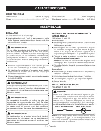
7 — English FEATURES INSTALLING/REMOVING WHEEL GUARD See Figure 1, page 13. To install: Unlock the guard clasp by pulling the clasp out, away from the grinder. Place the guard on the shoulder of the bearing cap by aligning index dots on guard and bearing cap. Press down on guard until it is full...
Page 8 - INSTALLING THE SIDE HANDLE
8 — English ASSEMBLY DANGER: Never attach a wood cutting or carving blade of any type to this grinder. It is only designed for grinding and sand-ing. Use for any other purpose is not recommended and creates a hazard, which will result in serious injury. WARNING: Thoroughly inspect a new grinding whe...
Page 9 - OPERATION; APPLICATIONS; To turn the tool OFF:; POSITIONING THE GUARD; To reposition the guard:; OPERATING THE GRINDER; To operate the grinder:
9 — English OPERATION WARNING: Always wear eye protection with side shields marked to comply with ANSI Z87.1, along with hearing protection. Failure to do so could result in objects being thrown into your eyes and other possible serious injuries. WARNING: Do not use any attachments or accessories no...
Page 10 - INSTALLING/REMOVING CUTTING WHEEL
10 — English Turn on the grinder and let the motor and grinding wheel build up to full speed. Lower the grinder gradually until the grinding wheel contacts the workpiece. WARNING: To prevent loss of control and possible serious personal injury, always operate the grinder with both hands, keep-in...
Page 11 - To make the best possible cut:
11 — English Fit the flat side of the flange nut against the outside of the wheel and finger tighten. Depress the spindle lock button and rotate the wheel clockwise until the spindle locks in position. Tighten the flange nut securely with the wrench provided. Do not overtighten. To remo...
Page 12 - REPLACING THE GUARD; To replace the guard:; Positioning; MAINTENANCE; GENERAL MAINTENANCE; NOTE: ILLUSTRATIONS START ON PAGE 13 AFTER
12 — English REPLACING THE GUARD See Figure 1, page 13. WARNING: Do not change or loosen guard screw. Failure to heed this warning may cause the guard to become loose during operation resulting in serious personal injury. After extended use, the guard may wear and need replacing. If you drop the gri...
Page 13 - RÈGLES DE SÉCURITÉ GÉNÉRALES; SÉCURITÉ ÉLECTRIQUE
2 — Français RÈGLES DE SÉCURITÉ GÉNÉRALES AVERTISSEMENT ! Lire toutes les instructions. Le non-respect de toutes les instructions ci-dessous peut entraîner un choc électrique, un incendie et/ou des blessures graves. Le terme « outil motorisé », utilisé dans tous les avertissements ci-dessous désigne...
Page 14 - UTILISATION ET ENTRETIEN DE LA PILE; les yeux consulter un médecin.; DÉPANNAGE
3 — Français UTILISATION ET ENTRETIEN DE LA PILE S’assurer que le commutateur est en position d’arrêt avant d’insérer le bloc-piles. L’insertion du bloc-piles dans un outil dont le commutateur est en position de marche peut causer un accident. Ne recharger qu’avec l’appareil spécifié par le fabr...
Page 15 - RÈGLES DE SÉCURITÉ PARTICULIÈRES; REBONDS ET AVERTISSEMENTS CONNEXES
4 — Français RÈGLES DE SÉCURITÉ PARTICULIÈRES Porter de l’équipement de protection de qualité professionnelle. Selon le type d’opération, porter un masque de protection ou des lunettes de sécurité. Au besoin, porter également un masque antipoussières, un protecteur d’oreille, des gants et un tab...
Page 16 - RÈGLES SUPPLÉMENTAIRES DE SÉCURITÉ; Toujours utiliser le garde correct avec la meule.
5 — Français RÈGLES DE SÉCURITÉ PARTICULIÈRES Par exemple, ne pas meuler avec le côté d’une meule à tronçonner. Seule la périphérie des meules à tronçonner abrasives doit être utilisée pour le meulage. Le fait d’appliquer une force latérale sur ces meules peut provoquer leur éclatement. Toujours...
Page 17 - SYMBOLES
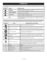
6 — Français SYMBOLES Certains des symboles ci-dessous peuvent être utilisés sur produit. Veiller à les étudier et à apprendre leur signification. Une interprétation correcte de ces symboles permettra d’utiliser produit plus efficacement et de réduire les risques. SYMBOLE NOM DÉSIGNATION / EXPLICATI...
Page 18 - CARACTÉRISTIQUES; FICHE TECHNIQUE; Positionnement du garde-meule; INSTALLATION DE LA MEULE; DÉBALLAGE; ASSEMBLAGE
7 — Français CARACTÉRISTIQUES FICHE TECHNIQUE Taille de meule ........................................115 mm (4 1/2 po) Moteur ................................................................... 18 V c.c. Vitesse nominale ..................................... 9 000 /min (RPM) Diamètre de broche .......
Page 19 - INSTALLATION DE LA POIGNÉE LATÉRALE
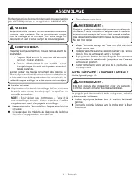
8 — Français ASSEMBLAGE Recherchez le pièce de protection de roue de coupe accessoire (p/n 204772004) en ligne ou en appelant au 1-800-525-2579. DANGER: Ne jamais installer de lame ou de ciseau à bois d’aucune sorte sur cette meuleuse. Elle est exclusivement conçue pour le meulage et le ponçage. Tou...
Page 20 - Pour mettre l’outil en MARCHE :; UTILISATION; Pour ARRÊTER l’outil; POSITIONNEMENT DU GARDE; Pour repositionner le garde :; UTILISATION DE LA MEULEUSE; Utilisation de la meuleuse :
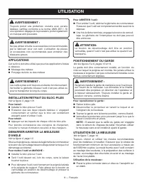
9 — Français AVERTISSEMENT : Toujours porter une protection oculaire avec écrans latéraux certifiée conforme à la norme ANSI Z87.1. Si une opération dégage de la poussière, porter également un masque anti-poussière. AVERTISSEMENT : Ne pas utiliser d’outils ou accessoires non recommandés par le fabri...
Page 21 - Pour enlever
10 — Français DANGER : Ne jamais utiliser la meuleuse sans le garde. Elle est conçue pour n’être utilisée qu’avec le garde en place. Si cette précaution n’est pas prise, de la limaille peut être en direction de l’opérateur et causer des blessures graves. Tenir la meuleuse devant soi, loin du corps...
Page 22 - Pour obtenir une qualité de coupe maximum :
11 — Français Appuyer sur le levier et tourner le garde-meule en position correcte. Voir la section Positionnement du garde- meule . NOTE : S’assurer que la nervure en saillie du garde-meule est engagée dans la rainure du chapeau de roulement. Placer la flasque de disque sur la broche. S’assur...
Page 23 - REMPLACEMENT DE LA GARDE; Pour remplacer le garde :; Positionnement du garde; ENTRETIEN; ENTRETIEN GÉNÉRAL; ILLUSTRATIONS COMMENÇANT SUR 13 DE PAGE
12 — Français REMPLACEMENT DE LA GARDE See Figure 1, page 12. AVERTISSEMENT : Ne pas remplacer ni desserrer la vis de le garde. Le non-respect de cet avertissement peut provoquer le détachement de le garde au cours du fonctionnement et blesser gravement l’opérateur. Après un certain temps, le garde ...
Page 24 - REGLAS DE SEGURIDAD GENERALES; GUARDE ESTAS INSTRUCCIONES; SEGURIDAD ELÉCTRICA
2 — Español REGLAS DE SEGURIDAD GENERALES ¡ADVERTENCIA! Lea todas las instrucciones. El incumplimiento de las instrucciones señaladas abajo puede causar descargas eléctricas, incendios y lesiones serias. El término “herramienta eléctrica” empleado en todos los avisos de advertencia enumerados abajo ...
Page 25 - ADVERTENCIAS DE SEGURIDAD GENERALES; REGLAS DE SEGURIDAD ESPECÍFICAS; EMPLEO Y CUIDADO DE LA HERRAMIENTA; No exponga el paquete de baterías o el artefacto al; SERVICIO
3 — Español REGLAS DE SEGURIDAD GENERALES ADVERTENCIAS DE SEGURIDAD GENERALES PARA LAS OPERACIONES DE ESMERILADO, LIJADO, CEPILLO DE ALAMBRE Y PULIR Esta herramienta eléctrica está diseñada para funcionar como una amoladora, una lijadora, un cepillo de alambre o una enceradora. Lea todas las adver...
Page 26 - CONTRAGOLPE Y ADVERTENCIAS
4 — Español REGLAS DE SEGURIDAD ESPECÍFICAS El diámetro exterior y el espesor del accesorio deben tener la capacidad nominal de su herramienta eléctrica. Los accesorios de un tamaño incorrecto no pueden protegerse ni controlarse de forma adecuada. El diámetro del árbol de las ruedas, las bridas,...
Page 27 - LIJADO
5 — Español ADVERTENCIAS DE SEGURIDAD ESPECÍFICAS PARA LAS OPERACIONES DE ESMERILADO Sólo utilice los tipos de discos recomendados para su herramienta eléctrica y el protector específico diseñado para el disco seleccionado. Los discos que no fueron diseñados para la herramienta eléctrica no pueden...
Page 28 - SÍMBOLOS; SÍMBOLO
6 — Español SÍMBOLOS Es posible que se empleen en este producto algunos de los siguientes símbolos. Le suplicamos estudiarlos y aprender su significado. Una correcta interpretación de estos símbolos le permitirá utilizar mejor y de manera más segura el producto. SÍMBOLO NOMBRE DENOMINACIÓN/EXPLICACI...
Page 29 - CARACTERÍSTICAS; ESPECIFICACIONES DEL PRODUCTO; Posicionamiento de la protección de la; DESEMPAQUETADO; ARMADO
7 — Español CARACTERÍSTICAS ESPECIFICACIONES DEL PRODUCTO Capacidad de la muela abrasiva ...... 114 mm (4-1/2 pulg.)Motor ......................................................... 18 V, corr. cont. Velocidad clasificada .............................. 9 000 /min (RPM)Rosca del husillo ..................
Page 30 - INSTALACIÓN DE LAS MUELAS ABRASIVAS; INSTALACIÓN DEL MANGO LATERAL
8 — Español ARMADO INSTALACIÓN DE LAS MUELAS ABRASIVAS Vea la figura 1, página 13 . PELIGRO: Utilice ÚNICAMENTE muelas abrasivas con el centro más bajo Tipo 27 (como la que acompaña a este producto). No se deben utilizar discos rectos o de corte tipo 1 sin la protección adecuada. Utilice para cualqu...
Page 31 - FUNCIONAMIENTO; APLICACIONES; POSICIONAMIENTO DE LA PROTECCIÓN; UTILIZACIÓN DE LA AMOLADORA
9 — Español FUNCIONAMIENTO ADVERTENCIA: Siempre póngase protección ocular con protección lateral con la marca de cumplimiento de la norma ANSI Z87.1. La inobservancia de esta advertencia puede permitir que los objetos lanzados hacia los ojos puedan provocarle lesiones graves. ADVERTENCIA: No utilice...
Page 34 - MANTENIMIENTO GENERAL; MANTENIMIENTO; REEMPLAZO DE LA PROTECCIÓN; Para cambiar la protección:; Posicionamiento de la protección,
12 — Español ADVERTENCIA: Al dar servicio a la herramienta, utilice solamente piezas de repuesto idénticas. El empleo de piezas diferentes puede implicar peligro o causar daños al producto. ADVERTENCIA: Siempre póngase protección ocular con protección lateral con la marca de cumplimiento de la norma...
Page 40 - OPERATOR’S MANUAL; MANUEL D’UTILISATION / MANUAL DEL OPERADOR; 8 V ANGLE GRINDER
998000812 9-23-21 (REV:02) OPERATOR’S MANUAL MANUEL D’UTILISATION / MANUAL DEL OPERADOR 18 V ANGLE GRINDER MEULEUSE D’ANGLE DE 18 V AMOLADORA ANGULAR DE 18 V PCL445 RYOBI is a registered trademark of Ryobi Limited and is used pursuant to a license granted by Ryobi Limited. TECHTRONIC INDUSTRIES POWE...