Ryobi PBLHM101B-A971001 - Manuals

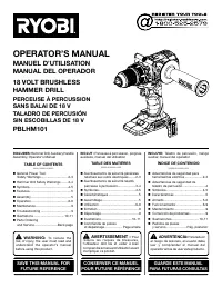
User Manual Ryobi PBLHM101B-A971001


Summary
2 — English GENERAL POWER TOOL SAFETY WARNINGS WARNING Read all safety warnings, instructions, illustrations and specifications provided with this power tool. Failure to follow all instructions listed below may result in electric shock, fire and/or serious injury. Save all warnings and instructions ...
3 — English GENERAL POWER TOOL SAFETY WARNINGS HAMMER DRILL SAFETY WARNINGS Wear ear protectors with impact drilling. Exposure to noise can cause hearing loss. Use auxiliary handle(s), if supplied with the tool. Loss of control can cause personal injury. Hold power tool by insulated gripping s...
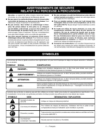
4 — English The following signal words and meanings are intended to explain the levels of risk associated with this product. SYMBOL SIGNAL MEANING DANGER: Indicates a hazardous situation, which, if not avoided, will result in death or serious injury. WARNING: Indicates a hazardous situation, which, ...
Ryobi Hammer Drills Manuals
-
 Ryobi D620H
User Manual
Ryobi D620H
User Manual
-
 Ryobi P214-PSK005
User Manual
Ryobi P214-PSK005
User Manual
-
 Ryobi P223
User Manual
Ryobi P223
User Manual
-
 Ryobi P223K1
User Manual
Ryobi P223K1
User Manual
-
 Ryobi PBLHM101B
User Manual
Ryobi PBLHM101B
User Manual
-
 Ryobi PBLHM101B-PBP003
User Manual
Ryobi PBLHM101B-PBP003
User Manual
-
 Ryobi PBLHM101K
User Manual
Ryobi PBLHM101K
User Manual
-
 Ryobi PCL220B
User Manual
Ryobi PCL220B
User Manual
-
 Ryobi PSBHM01B
User Manual
Ryobi PSBHM01B
User Manual
-
 Ryobi PSBHM01K
User Manual
Ryobi PSBHM01K
User Manual
-
 Ryobi PSBHM01K-A98401
User Manual
Ryobi PSBHM01K-A98401
User Manual
-
 Ryobi PSBHM01K-A989504
User Manual
Ryobi PSBHM01K-A989504
User Manual
-
 Ryobi PSBRH01B
User Manual
Ryobi PSBRH01B
User Manual
-
 Ryobi PSBRH01K1
User Manual
Ryobi PSBRH01K1
User Manual
-
 Ryobi SDS65
User Manual
Ryobi SDS65
User Manual