Rinnai RSEP1S25N - Manuals

User Manual Rinnai RSEP1S25N


Summary
2 SE+ Series Infrared G as Heater I nstallation and Operatio n Manual NOTICE: Rinnai reserves the right to make changes to equipment and specifications without obligation or notification. This publication, or parts thereof, may not be reproduced in any form, without prior written consent from Rinnai...
3 SE+ Series Infrared G as Heater I nstallation and Operatio n Manual TABLE OF CONTENTS TOPIC PAGE NUMBER IMPORTANT INFORMATION - READ FIRST IM PORTANT WARNINGS ........................... 4 HEATER EXPANSION ................................ 5 GAS CONNECTION .................................... 5 VEN...
4 SE+ Series Infrared G as Heater I nstallation and Operatio n Manual This heater is not for installation in a Class 1 or Class 2 explo- sive environment, nor f or any residential application. If installa- tion of this equipment is in question, consult with local authorities having jurisdiction (Fir...
Rinnai Heaters Manuals
-
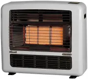
 Rinnai 151L
User Manual
Rinnai 151L
User Manual
-
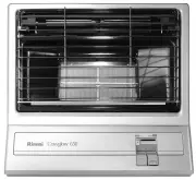
 Rinnai 151N
User Manual
Rinnai 151N
User Manual
-
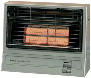
 Rinnai 151SL
User Manual
Rinnai 151SL
User Manual
-
 Rinnai 151SN
User Manual
Rinnai 151SN
User Manual
-
 Rinnai 252L
User Manual
Rinnai 252L
User Manual
-
 Rinnai 252N
User Manual
Rinnai 252N
User Manual
-
 Rinnai 252SL
User Manual
Rinnai 252SL
User Manual
-
 Rinnai 252SL2
User Manual
Rinnai 252SL2
User Manual
-
 Rinnai 252SN
User Manual
Rinnai 252SN
User Manual
-
 Rinnai 252SN2
User Manual
Rinnai 252SN2
User Manual
-
 Rinnai 252WL2
User Manual
Rinnai 252WL2
User Manual
-
Rinnai 252WN2
User Manual
-
 Rinnai 650SL
User Manual
Rinnai 650SL
User Manual
-
 Rinnai 650SN
User Manual
Rinnai 650SN
User Manual
-
 Rinnai 850SL
User Manual
Rinnai 850SL
User Manual
-
 Rinnai 850SN
User Manual
Rinnai 850SN
User Manual
-
 Rinnai AH083CP
User Manual
Rinnai AH083CP
User Manual
-
 Rinnai AH083P
User Manual
Rinnai AH083P
User Manual
-
Rinnai AH084CP
User Manual
-
Rinnai AH084P
User Manual