Rinnai RHFE-431WTA - Manuals
Rinnai RHFE-431WTA – Manual in PDF format online.
Manuals:
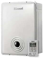
Manual Rinnai RHFE-431WTA


Summary
WARNING IMPROPER INSTALLATION, ADJUSTMENT, ALTERATION,SERVICE OR MAINTENANCE CAN CAUSE PROPERTYD A M A G E , P E R S O N A L I N J U R Y O R L O S S O F L I F E .R E F E R T O T H E O W N E R ' S I N F O R M AT I O N M A N U A LPROVIDED WITH THIS APPLIANCE. INSTALLATION ANDS E R V I C E M U S T B E ...
TECHNICAL DATA – 2 – Burner Orifices:RHFE-431WTA-P use: Orifice part #AU129-210 × 02-0.85(0.033") RHFE-431WTA-N use: Orifice part #AU129-210 × 02-1.13(0.044") GAS CONVERSION SPECIFICATIONS WEIGHT DIMENSIONS GAS RATE (BTU/h) 51 Lbs. Width: 29 1/2 " Height: 21 13/16 " Depth: 9 13/16 &#...
– 4 – DIMENSIONS 21 13/16" (554mm) 19 15/16" (506mm) 8 7/16"(214mm) Power supply cable 29 1/2" (750mm) 8 9/16" (217mm) 9 5/8" (245mm) Exhaust at rear of unit 3 7/16" (88mm) 11 " (280mm) R8.0" (R206mm) R11" (R279mm) 1" (25mm) 3" 18" Gas Inlet 3 3/...
Rinnai Manuals
-
 Rinnai RB-206GMF/207EMF
Manual
Rinnai RB-206GMF/207EMF
Manual
-
 Rinnai EX11C (RHFE-265FTA)
Manual
Rinnai EX11C (RHFE-265FTA)
Manual
-
 Rinnai FS35ETRSL
Manual
Rinnai FS35ETRSL
Manual
-
 Rinnai E110CN
Manual
Rinnai E110CN
Manual
-
 Rinnai ES38
Manual
Rinnai ES38
Manual
-
 Rinnai RC80HPI
Manual
Rinnai RC80HPI
Manual
-
Rinnai E75CN
Manual
-
 Rinnai R50LSI
Manual
Rinnai R50LSI
Manual
-
 Rinnai RHFE-750ETRA
Manual
Rinnai RHFE-750ETRA
Manual
-
 Rinnai REU - 16 FUA - E
Manual
Rinnai REU - 16 FUA - E
Manual
-
 Rinnai 37AHB
Manual
Rinnai 37AHB
Manual
-
 Rinnai RL75I
Manual
Rinnai RL75I
Manual
-
 Rinnai 26i, HD50i
Manual
Rinnai 26i, HD50i
Manual
-
 Rinnai Q175CP
Manual
Rinnai Q175CP
Manual
-
 Rinnai EX22
Manual
Rinnai EX22
Manual
-
 Rinnai MC-100V-1-S
Manual
Rinnai MC-100V-1-S
Manual
-
Rinnai R98LSI-ASME
Manual
-
Rinnai Q130SN
Manual
-
 Rinnai R94LSe
Manual
Rinnai R94LSe
Manual
-
 Rinnai EX17C
Manual
Rinnai EX17C
Manual