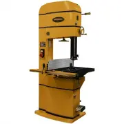
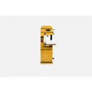
Powermatic PM1-1791258BT-4 - Manuals

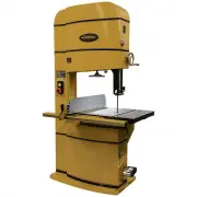
User Manual Powermatic PM1-1791258BT-4


Summary
2 Warranty and Service Walter M eier (M anufacturing) Inc., w arrants every product it sells. If one of our tools needs service or repair, one of our Authorized Service Centers located throughout the United States can give you quick service. In m ost cases, any of these Walter M eier Authorized Serv...
3 Table of Contents W arranty and Service ................................................................................................................................................... 2 Table of Contents .............................................................................................
5 Warni ng 1. Read and understand t he entire owner’s manual before attempting assembly or operation. 2. Read and understand t he war nings posted on t he mac hine and in this manual. Failure to comply wit h all of these warnings may caus e serious injury. 3. Replace t he warning labels if they beco...
Powermatic Band Saws Manuals
-
 Powermatic 1791216K
User Manual
Powermatic 1791216K
User Manual
-
 Powermatic 1791257B
User Manual
Powermatic 1791257B
User Manual
-
 Powermatic 1791257BT
User Manual
Powermatic 1791257BT
User Manual
-
 Powermatic 1791258B
User Manual
Powermatic 1791258B
User Manual
-
Powermatic 1791258BT
User Manual
-
Powermatic 1791258BT-4
User Manual
-
 Powermatic 1791259B
User Manual
Powermatic 1791259B
User Manual
-
Powermatic 1791259BT
User Manual
-
 Powermatic 1791260B
User Manual
Powermatic 1791260B
User Manual
-
Powermatic 1791260BT
User Manual
-
Powermatic 1791260BT-4
User Manual
-
Powermatic 1791500T
User Manual
-
 Powermatic 1791800B
User Manual
Powermatic 1791800B
User Manual
-
Powermatic 1791800BT
User Manual
-
 Powermatic 1791801B
User Manual
Powermatic 1791801B
User Manual
-
Powermatic 1791801BT
User Manual
-
 Powermatic 1791801BT-4
User Manual
Powermatic 1791801BT-4
User Manual
-
 Powermatic PM1-1791257BT
User Manual
Powermatic PM1-1791257BT
User Manual
-
 Powermatic PM1-1791258BT
User Manual
Powermatic PM1-1791258BT
User Manual
-
 Powermatic PM1-1791259BT
User Manual
Powermatic PM1-1791259BT
User Manual