Page 2 - Warranty and service
2 1.0 Warranty and service Powermatic warrants every product it sells against manufacturers’ defects. If one of our tools needs service or repair, please contact Technical Service by calling 1-800-274-6846, 8AM to 5PM CST, Monday through Friday. Warranty Period The general warranty lasts for the tim...
Page 3 - Table of contents; Section
3 2.0 Table of contents Section Page 1.0 Warranty and service ..................................................................................................................................... 2 2.0 Table of contents ...................................................................................
Page 7 - About this manual; operation! Failure to comply may cause serious injury!; Features and Terminology
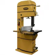
7 4.0 About this manual This manual is provided by Powermatic covering the safe operation and maintenance procedures for a Powermatic Model PM1800B, PM2013B and PM2415B Band Saw. This manual contains instructions on installation, safety precautions, general operating procedures, maintenance instruct...
Page 8 - Specifications
8 6.0 Specifications Model number ....................................................................................................... PM1800B .............. PM1800B-3 Stock number ........................................................................................................ 1791800B .....
Page 11 - Base hole centers
11 7.0 Base hole centers PM1800B PM2013B PM2415B Figure 2
Page 12 - Setup and assembly; Shipping contents; Read and understand all; Unpacking; Exercise care when removing
12 8.0 Setup and assembly 8.1 Shipping contents Carton contents (see Figure 3) 1 Band saw 1 Fence plate – A 1 Fence body – B 1 Resaw pin – C 1 Fence lever knob – D 1 Resaw pin lock knob – E 2 Eye bolts – F 1 Miter gauge – G 1 Front rail – H 1 Rear rail – J 1 Guide rail – K Figure 3: contents (items ...
Page 13 - Front rail and guide rail; Fence assembly
13 Exposed metal surfaces, such as table surface and blade guides, have been given a protective coating at the factory. This coating should be removed with a soft cloth moistened with solvent. Do not get solvents near plastic or rubber parts; and do not use an abrasive pad as it may scratch the expo...
Page 14 - Resaw fence; Fence to table clearance; Setting table parallel to blade
14 8.7 Resaw fence Refer to Figures 8 and 9. Loosen lock bar using the knobs, until lock bar protrudes enough to slide aluminum resaw fence on from either end, as shown in Figure 8. Re-tighten knobs. NOTE: The aluminum resaw fence can be installed in one of two positions; vertically (resaw position)...
Page 15 - Setting fence parallel to blade
15 at both front and back of table – these should be the same. 5. If miter slot is not parallel to blade, loosen the four hex cap screws (17mm wrench) that secure the table to the trunnion (Figure 14 shows three of them), and shift table as needed until miter slot is parallel to blade. 6. Tighten th...
Page 16 - Fence locking tightness; Dust collection; Electrical connections; Electrical connections must be; Single phase connections; Local codes take precedence over; Local codes take precedence over; Voltage conversion; Grounding instructions
16 8.12 Fence locking tightness Tightness of the fence against the guide rail can be adjusted by rotating the two back screws (B, Figure 16). Rotate the two screws equally (clockwise to tighten) with the hex wrench. Because these screws are also used to align the fence to the blade, after adjusting ...
Page 17 - Extension cords; Adjustments; Table tilt; right tilt; 0° table stop
17 9.4 Extension cords Use of extension cords is discouraged; try to position machines within reach of the power source. If an extension cord becomes necessary, be sure to use one heavy enough to carry the current your product will draw. An undersized cord will cause a drop in line voltage resulting...
Page 18 - Installing/changing blades; Always wear gloves when; Blade tension
18 Figure 21: setting table stop 10.3 Installing/changing blades Always wear gloves when handling blades. New blades are usually packaged in a coiled position; to prevent injury uncoil them slowly and carefully, while wearing work gloves and safety glasses. Refer to sect. 6.0, Specifications , for m...
Page 19 - Blade tracking; Blade guides; Upper blade guides
19 4. Rotate tension handwheel (C, Figure 24) until scale pointer (Figure 25) reaches appropriate measurement for blade width. Figure 25: blade tension scale TIP: Use the band saw’s gauge setting initially. As you become familiar with the machine and with the different properties of band saw blades,...
Page 20 - Upper thrust bearing
20 Figure 27: upper blade guide adjustment Figure 28: upper blade guide adjustment 5. Move entire guide bracket by rotating knurled knob (B) until front of guide bearings are about 0.015” (1/64”) behind blade gullet (curved area at base of tooth). See Figure 29. Figure 29: guide bearing position 6. ...
Page 21 - Guide post; Guide post parallelism
21 4. Make sure all screws, knobs and lever are tightened when adjustments are complete. Figure 31: lower blade guides NOTE: The locking lever (G, Figure 31) can be re-positioned for convenience. Simply pull out on lever, rotate it on hub, and release it. Make sure it re-seats itself on hub. 10.9 Gu...
Page 22 - Miter gauge; Blade speed adjustment
22 10.12 Miter gauge Refer to Figures 34 and 35. A miter gauge is provided for crosscutting operations. Install miter gauge by sliding the end of miter gauge bar into table’s T-slot. The miter gauge should fit snugly within miter slot while still sliding easily. The bar of the miter gauge has two sl...
Page 23 - Drive belt tension and
23 Figure 36: belt detension Figure 37: belt position Figure 38: belt deflection 10.14 Drive belt tension and replacement The drive belt and pulleys are properly adjusted at the factory. However, belt tension should be occasionally checked when the band saw is new, as a new belt may stretch slightly...
Page 24 - Operating controls; Safety key
24 10.15 Wheel brush Refer to Figure 39. The brush (A) must contact tire to clear it of dust and debris before it touches the blade. Loosen screw to make adjustments to brush position. Retighten after positioning. 10.16 Insert block Refer to Figure 39. The insert block (B) should remain in position ...
Page 25 - Operation; General procedure; Whenever possible, use a push; When cutting, do not overfeed; Ripping; Using the fence in conjunction; Resawing
25 12.0 Operation The following section contains basic information, and is not intended to cover all possible applications or techniques using the Band Saw. Consult published sources of information, acquire formal training, and/or talk to experienced Band Saw users to gain proficiency and knowledge ...
Page 26 - Blade Lead
26 The ideal blade for resawing is the widest one the machine can handle, as the wider the blade the better it can hold a straight line. Resawing can be performed using the aluminum resaw fence or the resaw pin. When using the resaw fence, use a push block, push stick, or similar device to keep your...
Page 27 - Maintenance; Before doing maintenance on; Lubrication Points
27 13.0 Maintenance Before doing maintenance on the machine, disconnect it from the electrical supply by pulling out the plug or switching off the main switch! Failure to comply may cause serious injury. Clean the band saw regularly to remove any resinous deposits and sawdust. Keep the miter slot, a...
Page 28 - Blade Selection; Width; Shape
28 14.0 Blade Selection Using the proper blade for the job will increase the operating efficiency of your band saw, help reduce necessary saw maintenance, and improve your productivity. Thus, it is important to follow certain guidelines when selecting a saw blade. Here are factors to consider when s...
Page 29 - Set; Material
29 Figure 52 – Blade Set 14.4 Set The term “set” refers to the way in which the saw teeth are bent or positioned. Bending the teeth creates a kerf that is wider than the back of the blade. This helps the operator more easily pivot a workpiece through curve cuts, and decreases friction between blade ...
Page 30 - Blade Selection Guide
30 15.0 Blade Selection Guide Identify the material and thickness of your workpiece. The chart will show the recommended PITCH, blade TYPE, and FEED RATE. Key: H – Hook L – Low S – Skip M – Medium R – Regular H – High Example: 10/H/M means 10 teeth per inch / Hook Type Blade / Medium Feed For Radius...
Page 31 - Operational Problems; Symptom Possible
31 16.0 Troubleshooting PM1800B/2013B/2415B Band Saws 16.1 Operational Problems Table 3 Symptom Possible Cause Correction Table tilt does not hold position under load. Locking lever is not tight. Tighten locking lever (A, Figure 19). Trunnion locking mechanism is broken or worn. Replace trunnion loc...
Page 33 - Mechanical and Electrical Problems; Trouble Probable
33 16.2 Mechanical and Electrical Problems Table 4 Trouble Probable Cause Remedy Machine will not start/restart or repeatedly trips circuit breaker or blows fuses. No incoming power. Verify machine is connected to power source, and that the safety key is installed on the switch. Cord damaged. Replac...
Page 34 - Replacement Parts
34 Trouble Probable Cause Remedy Machine will not start/restart or repeatedly trips circuit breaker or blows fuses. (continued) Switch failure. If the start/stop switch is suspect, you have two options: Have a qualified electrician test the switch for function, or purchase a new start/stop switch an...
Page 39 - Parts List; Index No Part No
39 17.1.5 Complete Machine with Accessories – PM1800B, PM2013B and PM2415B – Parts List Index No Part No Description Size Qty 1 ................ PM2000-105 .............. Powermatic Nameplate, Large ................................ ...................................... 1 2 ................ PM1800B-...
Page 44 - Description
44 17.3.1 Lower Wheel Assembly – Exploded View Part Assembly No.: PM1800B-022 (#1~8) / PM2013B-022 (#1~7) / PM2415B-022 (#1~7) 17.3.2 Lower Wheel Assembly – Parts List Index No. Part No. Description Size Qty 1 ................ PM1800B-022-01 ...... Lower Wheel ..........................................
Page 55 - Electrical Connections; Electrical Connections – 5HP 1PH 230V
55 18.0 Electrical Connections 18.1 Electrical Connections – 5HP 1PH 230V MOTOR at 230V 1PH 5HP CONTROL PANEL FOOT BRAKE RUN CAPACITOR 45uF 450VAC START CAPACITOR 300MFD 250VAC 230V WHITE BLACK G R O UND U V S R V U S et a t 2 2A MAGNETIC SWITCH ASSEMBLY LIMIT SWITCH 11 12 24 23 NO C NC RED YELLOW B...
Page 56 - Electrical Connections – 5HP 3PH 230V
56 18.2 Electrical Connections – 5HP 3PH 230V MOTOR at 230V 3PH 5HP CONTROL PANEL FOOT BRAKE 230V WHITE BLACK GR OUND U W T R W V S et at 15A MAGNETIC SWITCH ASSEMBLY LIMIT SWITCH 11 12 24 23 NO C NC RED YELLOW BL A C K WH IT E WH IT E WH IT E WH IT E BLACK BLACK BL AC K RE D GREEN RED BLACK G R EEN...
Page 57 - Electrical Connections – 5HP 3PH 460V
57 18.3 Electrical Connections – 5HP 3PH 460V MOTOR at 460V 3PH 5HP CONTROL PANEL FOOT BRAKE 230V WHITE BLACK GR OUN D U W T R W V S et at 7 .5A MAGNETIC SWITCH ASSEMBLY LIMIT SWITCH 11 12 24 23 NO C NC RED YELLOW BL AC K WH ITE WH ITE WHITE WHITE BLACK BLACK BL A C K RED GREEN RED BLACK GR E E N GR...
Page 60 - 27 New Sanford Road
60 427 New Sanford Road LaVergne, Tennessee 37086 Phone: 800-274-6848 www.powermatic.com