Page 2 - – A POTENTIAL HAZARD THAT WILL CAUSE SERIOUS INJURY OR LOSS OF LIFE.; RISK OF FIRE OR EXPLOSION.; it immediately with a new tank or replace the entire compressor.; RISK OF ELECTRICAL SHOCK.
2 - ENG 200-2824 SAFETY GUIDELINES .......................................................... 2-4 GLOSSARY OF TERMS .......................................................... 4 OVERVIEW ........................................................................... 4-5 ASSEMBLY ............................
Page 3 - in a well ventilated area when using tools that generate dust.; IMPORTANT SAFETY INSTRUCTIONS
3 - ENG 200-2824 RISK TO BREATHING/ INHALATION HAZARD. Always wear MSHA/NIOSH approved, properly fitting face mask or respirator and work in a well ventilated area when using tools that generate dust. Some dust created by power sanding, grinding, drilling and other construction activities contains c...
Page 4 - OVERVIEW; BASIC AIR COMPRESSOR COMPONENTS
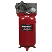
4 - ENG 200-2824 The basic components of the air compressor are the electric motor, pump, pressure switch and tank (see Fig. 1 ). The electric motor (see A ) powers the pump. The pump (see B ) compresses the air and discharges it into the tank. The tank (see C ) stores the compressed air. The pressu...
Page 5 - ASSEMBLY; ASSEMBLING THE COMPRESSOR
5 - ENG 200-2824 This compressor was shipped with oil in the pump crankcase. Check oil before operating the air compressor, see Check Oil under Maintenance. 1. Unpack the air compressor. Inspect the unit for damage. If the unit has been damaged in transit, contact the carrier and complete a damage c...
Page 6 - TYPICAL INSTALLATION; Air dryers and after coolers; inside the tank, not pressure in the air line; Air lubrication; Do not use a lubricator for paint spraying or similar; Shut–off valves; Compressor may vary from one shown.
6 - ENG 200-2824 TYPICAL INSTALLATION Risk of bursting, resulting in injury. Never use plastic pipe for compressed air. Never use lubricator for paint spraying or similar applications. WARNING: CAUTION: Air dryers and after coolers An air dryer or aftercooler is installed directly in the air line. M...
Page 7 - not; COMPRESSOR CONTROLS; NEVER force
7 - ENG 200-2824 Main Power Disconnect Install a main power disconnect switch in the power line to the compressor, near the compressor’s location. It is operated manually, but when it is in the ON position, the compressor will start up or shut down automatically based on air demand. ALWAYS operate t...
Page 8 - DO NOT; return the unit to the; OPERATING INSTRUCTIONS; SHUTDOWN
8 - ENG 200-2824 NOTE: The pump is shipped with break-in oil which should be changed after the first 8 hours of operation. 1. Make sure the power is connected at the power panel. 2. Check the oil level in the pump (see “Checking the Oil” in the maintenance section). 3. Open the petcock (see C ). Esc...
Page 9 - MAINTENANCE
9 - ENG 200-2824 MAINTENANCE This unit starts automatically. ALWAYS shut off the main power disconnect, and bleed all pressure from the system before servicing the compressor, and when the compressor is not in use. Do not use the unit with the shrouds or belt guard removed. Serious injury could occu...
Page 10 - TO REPLACE OR CLEAN CHECK VALVE
10 - ENG 200-2824 MAINTENANCE NOTE: Once the motor pulley has been moved from its factory set location, the grooves of the flywheel and pulley must be aligned to within 1/16” to prevent excessive belt wear. To check pulley alignment, remove the belt guard and place a straightedge (see A ) against th...
Page 11 - CHECKING THE RELIEF VALVE
11 - ENG 200-2824 MAINTENANCE SERVICE INTERVAL 9. Replace the transfer tube and tighten compression nuts. 10. Perform the “Break-in of the pump” procedure in the Operating Instructions to make sure there are no leaks and the check valve is working properly. A dirty air filter will reduce the compres...
Page 12 - TROUBLESHOOTING
12 - ENG 200-2824 Note: Troubleshooting problems may have similar causes and solutions. TROUBLESHOOTING PROBLEM POSSIBLE CAUSE SOLUTION Excessive current draw trips circuit breaker or motor reset switch Low voltage/motor overload Check that power supply is adequate and that compressor is on a dedica...
Page 13 - SPÉCIFICATIONS DE L’ALIMENTATION; TABLE DES MATIÈRES
200-2824 13 - FR 200-2824 CONSIGNES DE SÉCURITÉ ..................................... 13-15 GLOSSAIRE DES TERMES ........................................... 15 VUE D’ENSEMBLE .................................................... 15-16 ASSEMBLAGE ..........................................................
Page 14 - produits chimiques comprennent :; DIRECTIVES DE SÉCURITÉ IMPORTANTES
200-2824 14 - FR 200-2824 RISQUE RESPIRATOIRE. Toujours porter un masque recouvrant le visage qui est conforme aux normes MSHA/NIOSH et travailler dans un endroit bien ventilé lors de l’utilisation d’outils générant de la poussière. Certaines poussières provenant du sablage, de l’affilage, du perçag...
Page 15 - Pression de conjonction :; GLOSSAIRE DES TERMES; moteur électrique; VUE D’ENSEMBLE; ÉLÉMENTS DE BASE DU COMPRESSEUR D’AIR
200-2824 15 - FR 200-2824 DIRECTIVES DE SÉCURITÉ IMPORTANTES ATTENTION: Vidangez tous les jours l’humidité accumulée dans le réservoir. Pour éviter la corrosion, le réservoir doit être propre et sec.Tirer sur la bague de la soupape de sûreté du réservoir afin d’assurer que la soupape fonctionne corr...
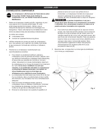
Page 16 - ASSEMBLAGE; ASSEMBLAGE DU COMPRESSEUR
200-2824 16 - FR 200-2824 Ce compresseur a été livré avec de l’huile dans le carter de la pompe. Vérifier l’huile avant d’utiliser le compresseur à air, voir Vérifier l’huile dans la section Maintenance. 1. Sortez le compresseur d’airde sa boîte. Inspectez–le pour vous assurer qu’il n’est pas endomm...
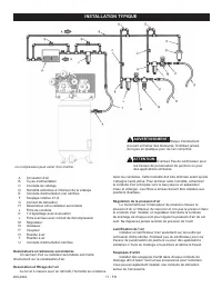
Page 17 - INSTALLATION TYPIQUE; Dessicateurs et radiateurs secondaires; à l’intérieur du réservoir et non pas la pression dans; Lubrification de l’air; N’utilisez pas de lubrificateur pour les; Soupapes d’arrêt; Le compresseur peut varier d’un montré.
200-2824 17 - FR 200-2824 INSTALLATION TYPIQUE Risque d’éclatement pouvant entraîner des blessures. N’utilisez jamais de tuyau en plastique pour de l’air comprimé. N’utilisez Pas de lubrificateur pour les travaux de pulvérisation de peinture ou pour des applications similaires. ADVERTISSEMENT: ATTEN...
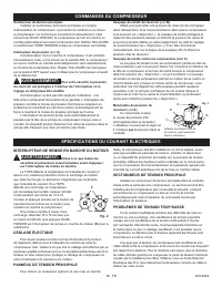
Page 18 - COMMANDES DU COMPRESSEUR; INTERRUPTEUR DE REMISE EN MARCHE DU MOTEUR; SPÉCIFICATIONS DU COURANT ÉLECTRIQUES; CÂBLAGE ÉLECTIQUE
200-2824 18 - FR 200-2824 Sectionneur de tension principale Installez un sectionneur de tension principale sur la ligne d’alimentation du compresseur, à proximité de l’endroit où se trouve le compresseur. Ce sectionneur est actionné manuellement, mais lorsqu’il est SOUS TENSION, le compresseur se me...
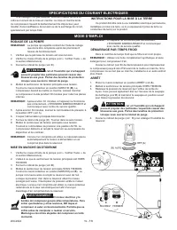
Page 19 - DÉMARRAGE PAR TEMPS FROID; MODE D’EMPLOI; RODAGE DE LA POMPE; INSTRUCTIONS POUR LA MISE À LA TERRE
200-2824 19 - FR 200-2824 REMARQUE : Le pompe qui expédié contient de l’huile de rodage que devra être remplacée après les premières 8 heures de fonctionnement. 1. Vérifiez que le panneau de tension est sous tension. 2. Vérifier le niveau d’huile de la pompe (voir « Vérifier l’huile » de la section ...
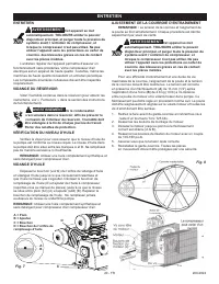
Page 20 - ENTRETIEN; D = Bouchon de l’orifice de
200-2824 20 - FR 200-2824 ENTRETIEN Cet appareil se met automatiquement. TOUJOURS arrêter le pouvoir disjoncteur principal, et purger toute la pression du système avant l ‘entretien du compresseur, et lorsque le compresseur n’est pas utilisé. Ne pas utiliser l’appareil sans les protections ou carter...
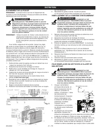
Page 21 - ALIGNEMENT DE LA POULIE
200-2824 21 - FR 200-2824 ENTRETIEN REMARQUE : La tension de la courroie et l’alignement de la poulie se font simultanément. Chaque procédure est décrite séparément par souci de clarté. Cet appareil se met automatiquement. TOUJOURS arrêter le pouvoir disjoncteur principal, et purger toute la pressio...
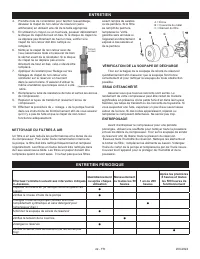
Page 22 - NETTOYAGE DU FILTRES À AIR; ENTRETIEN PÉRIODIQUE; Utilisez une huile
200-2824 22 - FR 200-2824 ENTRETIEN 4. Prendre note de l’orientation pour faciliter l’assemblage, dévisser le clapet de non-retour du réservoir (sens antihoraire) en utilisant une clé de la taille appropriée. 5. En utilisant un crayon ou un tournevis, pousser délicatement le disque du clapet de haut...
Page 23 - DÉPANNAGE
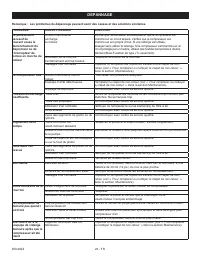
200-2824 23 - FR 200-2824 Remarque : Les problémes de dépannage peuvent avoir des causes et des solutions similaires. DÉPANNAGE PROBLÈME CAUSE POSSIBLE SOLUTION Le prélèvement excessif de courant cause le déclenchement du disjoncteur ou de l’interrupteur de remise en marche du moteur Tension insuffi...
Page 24 - - RIESGO POTENCIAL DE LESIONES GRAVES O PÉRDIDA DE LA VIDA.; INDICE; RIESGO DE INCENDIO O; RIESGO DE
200-2824 24 - SP 200-2824 PAUTAS DE SEGURIDAD INSTRUCCIONES IMPORTANTES DE SEGURIDAD La información que sigue se refiere a la protección de SU SEGURIDAD y la PREVENCIÓN DE PROBLEMAS DEL EQUIPO. Como ayuda para reconocer esta información, usamos los siguientes símbolos. Lea por favor el manual y pres...
Page 25 - INSTRUCCIONES IMPORTANTES DE SEGURIDAD
200-2824 25 - SP 200-2824 INSTRUCCIONES IMPORTANTES DE SEGURIDAD RIESGO Y PELIGRO POR INHALACIÓN. Cuando utilice herramientas que generen polvo, use siempre máscaras o respiradores ajustados y aprobados por la Administración de Minas, Seguridad y Salud (Mine Safety and Health Administration, MSHA) o...
Page 26 - motor eléctrico; RESUMEN GENERAL; COMPONENTES BÁSICOS DEL COMPRESOR DE AIRE; Presión de encendido:; GLOSARIO DE TÉRMINOS
200-2824 26 - SP 200-2824 Los componentes básicos del compresor de aire son el motor eléctrico, la bomba, el interruptor de presión y el depósito ( Fig. 1 ). El motor eléctrico (vea A ) acciona la bomba. La bomba (vea B ) comprime el aire y lo descarga hacia el depósito. El depósito (vea C ) almacen...
Page 27 - MONTAJE; MONTAJE DEL COMPRESOR
200-2824 27 - SP 200-2824 Este compresor viene con aceite en el cárter de la bomba. Compruebe el nivel de aceite antes de poner en funcionamiento el compresor de aire; consulte “Verificación del nivel de aceite”, en la sección de Mantenimiento. 1. Desembale el compresor de aire. Inspeccione la unida...
Page 28 - INSTALACIÓN TIPICA; Secadores de aire y post–enfriadores; en el interior del receptor y no la presión en la línea; Lubricación de aire; No utilice un lubricador para rociar; Válvulas de apagado; El compresor puede variar a partir del uno demostrado.
200-2824 28 - SP 200-2824 INSTALACIÓN TIPICA Existe el riesgo de lesiones pour quemaduras. Nunca use tubería de plástico para aire comprimido. Nunca use lubricador para rociar pintura o aplicaciones similares. ADVERTENCIA: PRECAUCIÓN: Secadores de aire y post–enfriadores El secador de aire o post-en...
Page 29 - INTERRUPTOR DE RESTABLECIMIENTO DEL MOTOR
200-2824 29 - SP 200-2824 Interruptor principal de alimentación Instale un interruptor principal de desconexión en la línea de alimentación hacia el compresor, cerca de la ubicación de éste. Este interruptor apaga el compresor. Se opera manualmente, pero cuando está en la posición de encendido ON, e...
Page 30 - INSTRUCCIONES OPERATIVAS; Si después de 30 minutos la unidad no funciona; PUESTA EN MARCHA INICIAL DE LA BOMBA; REQUISITOS DE ALIMENTACION ELECTRICA; INSTRUCCIONES DE PUESTA A TIERRA
200-2824 30 - SP 200-2824 INSTRUCCIONES OPERATIVAS NOTA: La bomba se envía con aceite para la puesta en marcha inicial, la cual debe cambiarse después de las primeras 8 horas de operación. 1. Asegúrese de que la energía esté conectada en el panel de alimentación. 2. Compruebe el nivel de aceite de l...
Page 31 - MANTENIMIENTO
200-2824 31 - SP 200-2824 MANTENIMIENTO Esta unidad arranca automáticamente. Apague SIEMPRE la unidad de alimentación principal y purgue toda la presión del sistema antes de realizar cualquier operación de mantenimiento en compresor y cuando el compresor no esté en uso. No utilice la unidad sin las ...
Page 32 - ALINEACIÓN DE LA POLEA
200-2824 32 - SP 200-2824 MANTENIMIENTO NOTA: El ajuste de la tensión de la correa de transmisión y la alineación de la polea se realizan al mismo tiempo. Se explican por separado para mayor claridad. Esta unidad arranca automáticamente. SIEMPRE apague el compresor, quite el enchufe de la toma de co...
Page 33 - REVISIÓN DE LA VÁLVULA DE DESCARGA; INTERVALOS DE SERVICIO; LIMPIEZA DEL FILTROS DE AIRE
200-2824 33 - SP 200-2824 MANTENIMIENTO válvula de retención. Retire el tubo de purga (E). 4. Tomando nota de la orientación para el montaje, desenroscar la válvula de retención del tanque (en sentido antihorario) utilizando la llave del tamaño apropiado. 5. Con un lápiz o destornillador, empuje con...
Page 34 - CUADRO DE DETECCIÓN DE FALLOS
200-2824 34 - SP 200-2824 Nota: Los problemas de detección de fallos pueden tener causas y soluciones similares. CUADRO DE DETECCIÓN DE FALLOS PROBLEMA CAUSA POSIBLE SOLUCION Consumo excesivo de la corriente hace saltar el cortacircuito o el interruptor de restablecimiento del motor Voltaje bajo/sob...
Page 35 - NOTES
Page 36 - PARTS AND SERVICE
Replacement parts and service are available from your nearest authorized Service Center. If the need arises, contact Product Service as listed at right. When consulting with a Service Center or Product Ser- vice, refer to the model number and serial number located on the serial label of the compress...