Omron LCM100- Manuals
Omron LCM100– User Manual in PDF format online.
Manuals:
User Manual Omron LCM100
1

2

3

4

5

6

7

8

9

10

Summary
Page 2 - FCC Information
DATA-LINC GROUP PN 161-xxxxx-001A Product User Guide FCC Information Appropriate FCC info
Page 3 - Line Carrier Modem; Introduction
DATA-LINC GROUP p LCM100 User’s Guide LCM100 Line Carrier Modem Introduction In the line carrier system, the hot line supplies current to connected loads and is also used as a carrier for data communication between modules. The Data-Linc LCM100 can communicate over the same line in a 240 volt single...
Page 4 - Initial Operation; Fuses
DATA-LINC GROUP p LCM100 User’s Guide Note: If a three-to-two-wire adapter is used to connect to a two-wire AC outlet, the ground lead of the adapter must be connected to earth ground to complete the ground system. An open ground connection may cause a communications defect and/or shock hazard. Line...
Omron Manuals
-
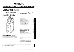 Omron VIBRATING MESH NEBULIZER NE-U22V
User Manual
Omron VIBRATING MESH NEBULIZER NE-U22V
User Manual
-
 Omron STRAPLESS HR-210
User Manual
Omron STRAPLESS HR-210
User Manual
-
 Omron sc100
User Manual
Omron sc100
User Manual
-
 Omron RS8
User Manual
Omron RS8
User Manual
-
Omron RS8
Manual
-
 Omron RS2
User Manual
Omron RS2
User Manual
-
Omron RS2
Manual
-
 Omron RS1
User Manual
Omron RS1
User Manual
-
Omron RS1
Manual
-
 Omron R6
User Manual
Omron R6
User Manual
-
Omron R6
Manual
-
 Omron RS6
User Manual
Omron RS6
User Manual
-
Omron RS6
Manual
-
 Omron R3
User Manual
Omron R3
User Manual
-
Omron R3
Manual
-
 Omron R2
User Manual
Omron R2
User Manual
-
Omron R2
Manual
-
 Omron Pedometer HJ-321
User Manual
Omron Pedometer HJ-321
User Manual
-
 Omron NE- C801KD
Manual
Omron NE- C801KD
Manual
-
 Omron NE-C801
User Manual
Omron NE-C801
User Manual