Omron E7- Manuals
Omron E7– User Manual, Manual in PDF format online.
Manuals:
User Manual Omron E7


Summary
366 3G3RV-P10ST @ -E PLC inverter Specifications by product General specifications Type designation Specifications Item 3G3RV-P10ST8-E 3G3RV-P10ST8-DRT-E PLC core CPM2C-S CPM2C-S Inputs 6 24 VDC inputs 6 24 VDC inputs Outputs 4 sourcing/PNP transistor outputs 4 sourcing/PNP transistor outputs Periph...
G7/F7/L7/E7 inverter PLC 369 The minimum pulse widths for inputs IN00000 (A-phase input) and IN00001 (B-phase input) are as follows: The minimum pulse width for input IN00002 (Z-phase input) is as follows: Interrupt inputs 3G3RV-P10ST is equipped with inputs that can be used as interrupt inputs (int...
370 3G3RV-P10ST @ -E CPU unit component descriptions 1. DIP switch • RS-232C and peripheral port settings • Operating mode at startup Pin 2 determines the operating mode at startup only if there isn't a programming device connected to the peripheral port. 2. Input indicators (yellow) The input indic...
Manual Omron E7


Summary
366 3G3RV-P10ST @ -E PLC inverter Specifications by product General specifications Type designation Specifications Item 3G3RV-P10ST8-E 3G3RV-P10ST8-DRT-E PLC core CPM2C-S CPM2C-S Inputs 6 24 VDC inputs 6 24 VDC inputs Outputs 4 sourcing/PNP transistor outputs 4 sourcing/PNP transistor outputs Periph...
G7/F7/L7/E7 inverter PLC 369 The minimum pulse widths for inputs IN00000 (A-phase input) and IN00001 (B-phase input) are as follows: The minimum pulse width for input IN00002 (Z-phase input) is as follows: Interrupt inputs 3G3RV-P10ST is equipped with inputs that can be used as interrupt inputs (int...
370 3G3RV-P10ST @ -E CPU unit component descriptions 1. DIP switch • RS-232C and peripheral port settings • Operating mode at startup Pin 2 determines the operating mode at startup only if there isn't a programming device connected to the peripheral port. 2. Input indicators (yellow) The input indic...
Omron Manuals
-
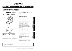 Omron VIBRATING MESH NEBULIZER NE-U22V
User Manual
Omron VIBRATING MESH NEBULIZER NE-U22V
User Manual
-
 Omron STRAPLESS HR-210
User Manual
Omron STRAPLESS HR-210
User Manual
-
 Omron sc100
User Manual
Omron sc100
User Manual
-
 Omron RS8
User Manual
Omron RS8
User Manual
-
Omron RS8
Manual
-
 Omron RS2
User Manual
Omron RS2
User Manual
-
Omron RS2
Manual
-
 Omron RS1
User Manual
Omron RS1
User Manual
-
Omron RS1
Manual
-
 Omron R6
User Manual
Omron R6
User Manual
-
Omron R6
Manual
-
 Omron RS6
User Manual
Omron RS6
User Manual
-
Omron RS6
Manual
-
 Omron R3
User Manual
Omron R3
User Manual
-
Omron R3
Manual
-
 Omron R2
User Manual
Omron R2
User Manual
-
Omron R2
Manual
-
 Omron Pedometer HJ-321
User Manual
Omron Pedometer HJ-321
User Manual
-
 Omron NE- C801KD
Manual
Omron NE- C801KD
Manual
-
 Omron NE-C801
User Manual
Omron NE-C801
User Manual