Page 2 - Support; Conformity; Compliance; Trademarks
2 S3300 Smart Managed Pro Switch Support Thank you for purchasing this NETGEAR product. You can visit www.netgear.com/support to register your product, get help, access the latest downloads and user manuals, and join our community. We recommend that you use only official NETGEAR support resources. C...
Page 3 - Contents; Chapter 1 Getting Started
3 Contents Chapter 1 Getting Started Getting Started with the NETGEAR Switch . . . . . . . . . . . . . . . . . . . . . . . . . . . . . . 11Switch Management Interface . . . . . . . . . . . . . . . . . . . . . . . . . . . . . . . . . . . . . . . . 12Connect the Switch to the Network . . . . . . . . ....
Page 4 - Chapter 3 Configuring Switching
4 S3300 Smart Managed Pro Switch Advanced Stack-Port Diagnostics . . . . . . . . . . . . . . . . . . . . . . . . . . . . . . . . . . . 86 Multiple Stack Links . . . . . . . . . . . . . . . . . . . . . . . . . . . . . . . . . . . . . . . . . . . . . . . . . 88PoE. . . . . . . . . . . . . . . . . . . ...
Page 5 - Chapter 4 Configuring Routing
5 S3300 Smart Managed Pro Switch Configure OUI-Based Auto-VoIP . . . . . . . . . . . . . . . . . . . . . . . . . . . . . . . . . . . 155Display Auto-VoIP Status . . . . . . . . . . . . . . . . . . . . . . . . . . . . . . . . . . . . . . . . . 156 Spanning Tree Protocol . . . . . . . . . . . . . . . ...
Page 6 - Chapter 5 Configuring Quality of Service
6 S3300 Smart Managed Pro Switch VLAN Routing Configuration . . . . . . . . . . . . . . . . . . . . . . . . . . . . . . . . . . . . . . . 215 Configure Router Discovery . . . . . . . . . . . . . . . . . . . . . . . . . . . . . . . . . . . . . . . . . 216 Configure and View Routes . . . . . . . . . ....
Page 7 - Chapter 7 Maintenance
7 S3300 Smart Managed Pro Switch Storm Control . . . . . . . . . . . . . . . . . . . . . . . . . . . . . . . . . . . . . . . . . . . . . . . . . . . 266Port Security Configuration . . . . . . . . . . . . . . . . . . . . . . . . . . . . . . . . . . . . . . . 267Port Security Interface Configuration ....
Page 8 - Appendix A Configuration Examples
8 S3300 Smart Managed Pro Switch Port Statistics . . . . . . . . . . . . . . . . . . . . . . . . . . . . . . . . . . . . . . . . . . . . . . . . . . . 318Port Detailed Statistics . . . . . . . . . . . . . . . . . . . . . . . . . . . . . . . . . . . . . . . . . . . 319EAP Statistics. . . . . . . . . ...
Page 9 - Getting Started; This manual describes how to configure and operate the ProSAFE
9 1 1. Getting Started This manual describes how to configure and operate the ProSAFE ® S3300 Smart Switch family by using the web-based graphical user interface (GUI). The manual describes the software configuration procedures and explains the options available within those procedures. The S3300 sw...
Page 11 - Getting Started with the NETGEAR Switch; This chapter contains the following sections:
Getting Started 11 S3300 Smart Managed Pro Switch Getting Started with the NETGEAR Switch This chapter provides an overview of starting your NETGEAR switch and accessing the user interface. It also leads you through the steps to use the Smart Control Center (SCC) application, which can be downloaded...
Page 12 - Switch Management Interface; Smart Control Center User Guide at
Getting Started 12 S3300 Smart Managed Pro Switch Switch Management Interface The NETGEAR switch contains an embedded web server and management software for managing and monitoring switch functions. The NETGEAR switch functions as a simple switch without the management software. However, you can use...
Page 13 - Connect the Switch to the Network; Dynamic assignment through DHCP; . DHCP is enabled by default on the switch. If you; Static assignment through the Smart Control Center; . If you connect the switch to a; Static assignment by connecting from a local host; . If you do not want to use the
Getting Started 13 S3300 Smart Managed Pro Switch Connect the Switch to the Network To enable remote management of the switch through a web browser or SNMP, you must connect the switch to the network and configure it with network information (an IP address, subnet mask, and default gateway). The swi...
Page 14 - Discover a Switch in a Network with a DHCP Server; To install the switch in a network with a DHCP server:
Getting Started 14 S3300 Smart Managed Pro Switch Discover a Switch in a Network with a DHCP Server This section describes how to set up your switch in a network that has a DHCP server. The DHCP client on the switch is enabled by default. When you connect it to your network, the DHCP server will aut...
Page 15 - Web Browser Access; Use your web browser to manage your switch. The default password is
Getting Started 15 S3300 Smart Managed Pro Switch Figure 2. Smart Control Center - Device List 7. Select your switch by clicking the line that displays the switch, then click the Web Browser Access button. The Smart Control Center launches a browser that displays the login screen of the selected dev...
Page 16 - Discover a Switch in a Network without a DHCP Server; To assign a static IP address:
Getting Started 16 S3300 Smart Managed Pro Switch Discover a Switch in a Network without a DHCP Server This section describes how to use the Smart Control Center to set up your switch in a network without a DHCP server. If your network has no DHCP service, you must assign a static IP address to your...
Page 17 - Type your password to continue with the configuration change.; Apply; button to configure the switch with the network settings.
Getting Started 17 S3300 Smart Managed Pro Switch Figure 3. Smart Control Center - Configure Device 9. Type your password to continue with the configuration change. Tip: You must enter the current password every time you use the Smart Control Center to update the switch setting. The default password...
Page 18 - To modify the network settings on your administrative system:; Open the Control Panel and click the; Network and Sharing Center; Click the; Local Area Connection; In the Local Area Connection Status window, click the; Properties; The Local Area Connection Properties window displays.
Getting Started 18 S3300 Smart Managed Pro Switch The method to change the IP address on an administrative system varies depending on the operating system version. You need Windows Administrator privileges to change these settings. The following procedures show how to change the static IP address on...
Page 19 - Select the; Use the following IP address; option and set the IP address of the administrative
Getting Started 19 S3300 Smart Managed Pro Switch Figure 5. Local Area Connection Properties Window 4. Select the Internet Protocol Version 4 (TCP/IPv4) option, and then click the Properties button. The Internet Protocol Version 4 (TCP/IPv4) Properties window appears. 5. Select the Use the following...
Page 20 - OK; For more information, see
Getting Started 20 S3300 Smart Managed Pro Switch WARNING: When you change the IP address of your administrative system, you lose your connection to the rest of the network. Be sure to write down your current network address settings before you change them. Figure 6. IP Address Settings 6. Click the...
Page 21 - Access the Management Interface from a Web Browser; Understand the User Interfaces; Use the Web Interface; Supported web browsers:
Getting Started 21 S3300 Smart Managed Pro Switch Access the Management Interface from a Web Browser To access the switch management interface, use one of the following methods: • From the Smart Control Center, select the switch and click the Web Browser Access button. For more information, see the ...
Page 22 - To log on to the web interface:
Getting Started 22 S3300 Smart Managed Pro Switch • Microsoft Edge • Mozilla Firefox versions 40, 46.0.1 • Chrome version 45 • Safari on Windows OS 5.1, 6.0 • Safari on Mac OS 8.0 To log on to the web interface: 1. Open a web browser and enter the IP address of the switch in the web browser addres...
Page 23 - Navigation Tabs, Configuration Menus, and Screen Menu; Configuration and Status Options
Getting Started 23 S3300 Smart Managed Pro Switch Navigation Tabs, Configuration Menus, and Screen Menu The navigation tabs along the top of the web interface give you quick access to the various switch functions. The tabs are always available and remain constant, regardless of which feature you con...
Page 24 - Device View; The Device View is a Java; System; The following image shows the Device View of the S3300-28X.
Getting Started 24 S3300 Smart Managed Pro Switch Device View The Device View is a Java ® applet that displays the ports on the switch. This graphic provides an alternate way to navigate to configuration and monitoring options. The graphic also provides information about device ports, current config...
Page 26 - Device View Main Menu; The System LEDs are located on the left side of the front panel.
Getting Started 26 S3300 Smart Managed Pro Switch Figure 13. Device View S3300-52X Port Menu If you click the graphic but do not click a specific port, the main menu appears, as Figure 14, Device View Main Menu shows. This menu contains the same option as the navigation menu at the top of the screen...
Page 27 - FAN Status LED; Help Access; Figure 7, Smart Switch Web Interface
Getting Started 27 S3300 Smart Managed Pro Switch Power/Status LED The Power LED is a bicolor LED that serves as an indicator of power and diagnostic status. The following indications are given by the following LED states: • A solid green LED indicates that the power is supplied to the switch and op...
Page 29 - Use SNMPv3; SNMP; Change
Getting Started 29 S3300 Smart Managed Pro Switch Use SNMPv3 The switch software supports the configuration of SNMP groups and users that can manage traps that the SNMP agent generates. The switch uses both standard public MIBs for standard functionality and private MIBs that support additional swit...
Page 30 - Interface Naming Convention
Getting Started 30 S3300 Smart Managed Pro Switch Interface Naming Convention The switch supports physical and logical interfaces. Interfaces are identified by their type and the interface number. All the physical ports are as follows: • S3300-28X. The ProSafe S3300-28X Smart switch is a stackable s...
Page 32 - Configuring Interface Settings; LAGS
Getting Started 32 S3300 Smart Managed Pro Switch Configuring Interface Settings For some features that allow you to configure interface settings, you can apply the same settings simultaneously to any of the following: • A single port • Multiple ports • All ports • A single LAG • Multiple LAGs • All...
Page 36 - Online Help; S3300 Smart Managed Pro Switch User Guide
Getting Started 36 S3300 Smart Managed Pro Switch 4. Click the Apply button. The settings you configure in the heading row are applied to all ports and LAGs. Online Help The Help main navigation tab of the web management interface provides access to the menus that are described in the following sect...
Page 37 - Registration; To register the switch with NETGEAR:; Select; Register
Getting Started 37 S3300 Smart Managed Pro Switch Registration To qualify for product updates and product warranty, NETGEAR encourages you to register your product. The first time that you connect to the switch while it is connected to the Internet, you have the option to register your product. At a...
Page 38 - Configure System Information; Use the features you access from the; navigation tab to define the switch’s relationship to; navigation tab provides access to the configuration menus
38 2 2. Configure System Information Use the features you access from the System navigation tab to define the switch’s relationship to its environment. The System navigation tab provides access to the configuration menus described in the following sections: • Management on page 39 • Device View on p...
Page 39 - Management; The; System Information
Configure System Information 39 S3300 Smart Managed Pro Switch Management This section describes how to display the switch status and specify some basic switch information, such as the management interface IP address, system clock settings, and DNS information. From the Management configuration menu...
Page 40 - System Name; Temperature Sensors; Update
Configure System Information 40 S3300 Smart Managed Pro Switch 2. Define the following fields: • System Name . Enter the name you want to use to identify this switch. You can use up to 255 alphanumeric characters. The factory default is blank. • System Location . Enter the location of this switch. Y...
Page 41 - Fans
Configure System Information 41 S3300 Smart Managed Pro Switch Figure 21. System Information - Temperature Sensors Status The following table describes the status information displayed in the Temperature Sensors section of the System Information screen. Table 5. System Information - Temperature Sens...
Page 42 - Power Supplies; This screen shows the power supplies status.; Versions; This screen displays the software version of each device.
Configure System Information 42 S3300 Smart Managed Pro Switch Power Supplies This screen shows the power supplies status. Figure 23. System Information - Power Supplies Status The following table describes the status information displayed in the Power Supplies section of the System Information scre...
Page 43 - System CPU Status
Configure System Information 43 S3300 Smart Managed Pro Switch The following table describes the information displayed in the Versions section of the System Information screen. Table 8. System Information - Versions Information Fields Field Description Unit No. The unit number of the switch. Model N...
Page 44 - Table 9; Click; to update the page with the latest information on the switch.; To configure the CPU Threshold information:
Configure System Information 44 S3300 Smart Managed Pro Switch Figure 25. System CPU Status - Unit CPU Utilization Table 9 describes the information that the System CPU Status screen displays. Table 9. System CPU Status > CPU Memory Status Field Description CPU Memory Status Total System Memory T...
Page 45 - USB Device Information
Configure System Information 45 S3300 Smart Managed Pro Switch Figure 26. CPU Threshold The CPU Threshold screen allows you to configure thresholds that, when crossed, trigger a notification. The notification is done via SNMP trap and SYSLOG messages. 1. Define the CPU Threshold fields listed in Tab...
Page 46 - To display the USB Device Information page:; USB Device Information.; screen displays as shown in; The write/read speed is about 1 Mbps due to a hardware limitation.
Configure System Information 46 S3300 Smart Managed Pro Switch To display the USB Device Information page: 1. Select System > Management > USB Device Information. 2. The USB Device Information screen displays as shown in Figure 27, USB Device Information . 3. Click Update to update the infor...
Page 47 - Slot Information; To display the Slot Information:
Configure System Information 47 S3300 Smart Managed Pro Switch Slot Information Use the Slot Information screen to display details about the different slots in the different units in the switch stack. To display the Slot Information: Select System > Management > Slot Information. Table 12 de...
Page 48 - IP Configuration
Configure System Information 48 S3300 Smart Managed Pro Switch Click Update to update the page with the latest information on the switch. IP Configuration Use the IP Configuration screen to configure network information for the management interface, which is the logical interface used for in-band co...
Page 49 - Static IP Address; VLANs
Configure System Information 49 S3300 Smart Managed Pro Switch • Static IP Address . Specifies that the IP address, subnet mask, and default gateway must be manually configured. Enter this information in the fields below this radio button. 3. If you selected the Static IP Address option, configure t...
Page 50 - IPv6 Network Configuration
Configure System Information 50 S3300 Smart Managed Pro Switch IPv6 Network Configuration Use the IPv6 Network Configuration screen to configure the IPv6 network interface, which is the logical interface used for in-band connectivity with the switch through all of the switch’s front-panel ports. The...
Page 51 - True
Configure System Information 51 S3300 Smart Managed Pro Switch features to acquire an IPv6 address. Auto configuration can be enabled only when DHCPv6 is not enabled on any of the management interfaces. • DHCPv6 . Next to Current Network Configuration Protocol, select DHCPv6 to enable the DHCPv6 cli...
Page 52 - IPv6 Network Neighbor; To display the IPv6 Network Neighbor screen:; IPv6 neighbor that the switch has discovered.
Configure System Information 52 S3300 Smart Managed Pro Switch IPv6 Network Neighbor Use the IPv6 Network Neighbor screen to view information about the IPv6 neighbors the device has discovered through the network interface by using the Neighbor Discovery Protocol (NDP). To display the IPv6 Network...
Page 53 - Time; Time Configuration
Configure System Information 53 S3300 Smart Managed Pro Switch Time The switch supports the Simple Network Time Protocol (SNTP). You can also set the system time manually. SNTP assures accurate network device clock time synchronization up to the millisecond. Time synchronization is performed by a ne...
Page 55 - SNTP Server Configuration
Configure System Information 55 S3300 Smart Managed Pro Switch 4. If the SNTP client mode is Unicast , use the SNTP Server Configuration screen to add the IP address or DNS name of one or more SNTP servers for the switch to poll. For more information, see SNTP Server Configuration on page 57. 5. In ...
Page 56 - The following table describes the SNTP Global Status fields.
Configure System Information 56 S3300 Smart Managed Pro Switch Figure 33. Time > SNTP Global Status The following table describes the SNTP Global Status fields. Table 14. Time Configuration status fields Field Description Version Specifies the SNTP version the client supports. Supported Mode Spec...
Page 58 - In the Version field, specify the NTP version running on the server.; Repeat the previous steps to add additional SNTP servers.
Configure System Information 58 S3300 Smart Managed Pro Switch Figure 34. SNTP Server Configuration 2. From the Server Type list, select the type of SNTP address to enter in the Address field, which is either an IP address (IPv4) or hostname (DNS). 3. In the Address field, specify the IP address or ...
Page 59 - Daylight Saving Configuration
Configure System Information 59 S3300 Smart Managed Pro Switch To remove an SNTP server: 1. Select the check box next to the configured server to remove. 2. Click the Delete button. To change the settings for an existing SNTP server: 1. Select the check box next to the configured server. 2. Spec...
Page 61 - Denial of Service
Configure System Information 61 S3300 Smart Managed Pro Switch - Day . Use this field to configure the end day. - Month . Use this field to configure the end month. - Hours . Use this field to configure the end hours. - Minutes . Use this field to configure the end minutes. 4. In the Offset field, s...
Page 62 - Configure Denial of Service
Configure System Information 62 S3300 Smart Managed Pro Switch Configure Auto-DoS The Auto- DoS Configuration screen lets you automatically enable all the DoS features available on the switch, except for the L4 Port attack. For information about the types of DoS attacks the switch can monitor and bl...
Page 63 - Denial of Service Min TCP Header Size; . Specify the minimum TCP header size; Denial of Service ICMPv4; . Enabling ICMPv4 DoS prevention causes the switch to; Denial of Service Max ICMPv4 Packet Size; . Specify the maximum ICMPv4 packet; Denial of Service ICMPv6; . Enabling ICMPv6 DoS prevention causes the switch to
Configure System Information 63 S3300 Smart Managed Pro Switch Figure 37. Denial of Service Configuration 2. Select the types of DoS attacks for the switch to monitor and block and configure any associated values: • Denial of Service Min TCP Header Size . Specify the minimum TCP header size allowed....
Page 64 - DNS
Configure System Information 64 S3300 Smart Managed Pro Switch • Denial of Service Max ICMPv6 Packet Size . Specify the maximum IPv6 ICMP packet size allowed. If ICMPv6 DoS prevention is enabled, the switch will drop IPv6 ICMP ping packets that have a size greater than this configured maximum ICMPv6...
Page 65 - Configure DNS
Configure System Information 65 S3300 Smart Managed Pro Switch Configure DNS Use this screen to configure global DNS settings and DNS server information. To configure the global DNS settings: 1. Select System > Management > DNS > DNS Configuration . Figure 38. DNS Configuration 2. Specify...
Page 66 - Configure and View Host Name-to-IP Address Information
Configure System Information 66 S3300 Smart Managed Pro Switch The Dynamic Host Configuration table shows host name-to-IP address entries that the switch has learned. The following table describes the dynamic host fields: Table 16. Dynamically learned host name mapping information Field Description ...
Page 67 - Green Ethernet; Green Ethernet Interface Configuration
Configure System Information 67 S3300 Smart Managed Pro Switch To change the host name or IP address in an entry: 1. Select the check box next to the entry to update. 2. Enter the new information in the appropriate field. 3. Click the Apply button. Green Ethernet Use this screen to configure Green...
Page 68 - Green Ethernet Detail
Configure System Information 68 S3300 Smart Managed Pro Switch Figure 41. Green Ethernet Interface Configuration 2. Select one or more ports to configure. • To configure a single port, select the check box associated with it, or type the port number in the Go To Interface field and click the Go butt...
Page 72 - From the; Green Ethernet Summary; To access the Green Ethernet Summary screen, select
Configure System Information 72 S3300 Smart Managed Pro Switch To display Green Ethernet mode settings for a Remote Device Figure 43. Remote Device Information 1. From the Interface list, select the interface. Table 18, Green Ethernet Local Device Information displays the following non-configurabl...
Page 73 - Table 19, Green Ethernet statistics summary
Configure System Information 73 S3300 Smart Managed Pro Switch Figure 44. Green Ethernet Summary Table 19, Green Ethernet statistics summary describes the information the Green Ethernet Statistics Summary table displays. Table 19. Green Ethernet statistics summary Field Description Current Power Con...
Page 74 - Table 20, Green Ethernet feature summary; View and Configure Green Ethernet LPI History
Table 20. Green Ethernet feature summary Field Description Unit The unit ID number, which is always 1. Green Features supported on this unit The Green Ethernet features the switch supports. Configure System Information 74 S3300 Smart Managed Pro Switch Table 20, Green Ethernet feature summary descri...
Page 75 - The following table describes the status fields on the screen.
Configure System Information 75 S3300 Smart Managed Pro Switch Figure 45. Green Ethernet LPI History 2. In the Sampling Interval field, specify the frequency, in seconds, at which EEE LPI history. 3. In the Max Samples to keep field, specify the maximum number of LPI samples to keep in the history b...
Page 76 - For Device View information, see; License; To view information about the license key, click
Configure System Information 76 S3300 Smart Managed Pro Switch Device View For Device View information, see Device View on page 24. License Some switch features require a special license in order to be active. If a license is not active, the feature associated with the license is not available and c...
Page 77 - Switch Stack Configuration; Stacking Overview; System-level (global) features that apply to all stack members
Configure System Information 77 S3300 Smart Managed Pro Switch Switch Stack Configuration Stacking Overview A stackable switch is a switch that is a fully functional operating standalone, but can also be set-up to operate together with up to six switches, with this group of switches showing the char...
Page 78 - Stack Firmware Synchronization; Stack Features
Configure System Information 78 S3300 Smart Managed Pro Switch the ability to synchronize the software on the stack unit with the software that is running on the stack manager. Normally, the software is automatically distributed to all units in the stack after downloading new code, but there can be ...
Page 79 - Firmware Upgrade Procedure
Configure System Information 79 S3300 Smart Managed Pro Switch Note: NETGEAR recommends assigning the highest priority value to the switch that you prefer to be the stack manager. This ensures that the switch is re-elected as stack manager if a re-election occurs. • The switch with the higher MAC ad...
Page 80 - Basic Stack Configuration; Management Unit Selection
Configure System Information 80 S3300 Smart Managed Pro Switch b. All stacking functionalities of the S3300 extend to these two M4300 platforms. However, Non-Stop Forwarding (NSF) is not supported. c. Either S3300 or M4300 can be stack master or standby. d. CLI under the console port is not supporte...
Page 81 - Stack Sample Mode; Stack Configuration
Configure System Information 81 S3300 Smart Managed Pro Switch Stack Sample Mode To configure the stack sampling parameters: 1. Select the Stack Sample Mode . The global status management mode which can be: • Cumulative. This tracks the sum of received time stamp offsets cumulatively. • History . ...
Page 82 - Basic Stack Status
Configure System Information 82 S3300 Smart Managed Pro Switch highest priority value will be chosen to become primary unit. If the value is set to 0, then that switch unit never participates in Manager Election. 5. Select the Management Status. Indicates whether the selected switch is the managemen...
Page 83 - Status; Advanced Stack Configuration
Configure System Information 83 S3300 Smart Managed Pro Switch Table 25. Basic Stack Table 26. Field Description Unit ID The Unit ID of the specific switch. Switch Description The description for the unit that can be configured by the user. Serial Number The unique box serial number for this switch....
Page 84 - Clear Sampling Information
Configure System Information 84 S3300 Smart Managed Pro Switch Figure 47. Advanced Stack Status The following table describes the non-configurable Advanced Stack Status data that is displayed. Click Refresh to update the page with the latest information on the switch. Table 27. Advanced Stack Status...
Page 85 - Advanced Stack-Port Configuration
Configure System Information 85 S3300 Smart Managed Pro Switch Advanced Stack-Port Configuration To configure a Stack-port: 1. Click System > Stacking > Advanced > Stack-port Configuration. Figure 48. Stack-Port Configuration 2. Select either the Unit ID or All . • Select the Unit ID fiel...
Page 86 - Advanced Stack-Port Diagnostics
Configure System Information 86 S3300 Smart Managed Pro Switch Advanced Stack-Port Diagnostics To display Stack-port diagnostics: Use the Stack-port Diagnostics page to display the diagnostics for all the stack-ports in the given stack. 1. Click System > Stacking > Advanced > Stack-port D...
Page 88 - mismatched stack; Multiple Stack Links
Configure System Information 88 S3300 Smart Managed Pro Switch The behavior of Firmware Synchronization is the same whether the system is powered on after connecting all the new members or if a new member is adding during the running operation of the stack. Stack Firmware Synchronization starts only...
Page 90 - PoE
Configure System Information 90 S3300 Smart Managed Pro Switch PoE Use this screen to configure a few system-level PoE parameters per unit. In other words, the parameters are specific to the whole unit, not specific to any port(s). 1. Select System > PoE > Basic > PoE Configuration . Figure...
Page 91 - Advanced PoE Configuration
Configure System Information 91 S3300 Smart Managed Pro Switch Advanced PoE Configuration The Advanced > PoE Configuration screen displays the same table as the Basic > PoE Configuration screen described above. However the Advanced screen allows you to configure a host of PoE parameters specif...
Page 93 - Legacy; Timer Schedule
Configure System Information 93 S3300 Smart Managed Pro Switch • 4pt 802.3af + legacy . 4-Point Resistive Detection in 802.3af mode, followed by Legacy Detection, is done. • Legacy . Only Legacy Detection is done. The factory default is IEEE 802. 9. Assign a Timer Schedule to the port. Select None t...
Page 95 - Configure the SNMPv1/v2 Community; Use this screen when you are using the SNMPv1 and SNMPv2 protocol.; To add an SNMP community:; In the Community String field, specify a community name.
Configure System Information 95 S3300 Smart Managed Pro Switch SNMP This section describes how to configure the Simple Network Management Protocol (SNMP) version 1 and SNMP version 2 information on the switch. For information about configuring the SNMPv3 administrative profile, see Use SNMPv3 on pag...
Page 96 - Trap Configuration
Configure System Information 96 S3300 Smart Managed Pro Switch If you select Enable, the community name must be unique among all valid community names or the set request will be rejected. If you select Disable, the community name will become invalid. 7. Click the Add button. To modify an existing ...
Page 97 - Trap Flags
Configure System Information 97 S3300 Smart Managed Pro Switch 3. Click the Apply button. To delete an SNMP trap recipient: 1. Select the check box next to the recipient to remove. 2. Click the Delete button. Trap Flags Use the Trap Flags screen to enable or disable traps the switch can send to an...
Page 98 - SNMP Supported MIBS; This screen displays a list of all MIBs supported by the switch.; The following table describes the fields on the screen.; LLDP; Device location discovery for creation of location databases.
Configure System Information 98 S3300 Smart Managed Pro Switch SNMP Supported MIBS This screen displays a list of all MIBs supported by the switch. To view the supported MIBs, select System > SNMP > SNMP V1/V2 > Supported MIBs. The following table describes the fields on the screen. Table 3...
Page 99 - LLDP Configuration
Configure System Information 99 S3300 Smart Managed Pro Switch • Inventory management, enabling network administrators to track their network devices and determine their characteristics (manufacturer, software and hardware versions, serial or asset number). LLDP Configuration Use the LLDP Configurat...
Page 100 - LLDP Port Settings
Configure System Information 100 S3300 Smart Managed Pro Switch LLDP Port Settings Use the LLDP Port Settings screen to specify per-interface LLDP settings. To configure LLDP port settings: 1. Select System > LLDP > Advanced > LLDP Port Settings . Figure 57. LLDP Port Settings 2. Select o...
Page 101 - LLDP-MED Network Policy
Configure System Information 101 S3300 Smart Managed Pro Switch information includes the system name, system description, system capabilities, and port description. For information about how to configure the system name, see Management on page 39. For information about how to configure the port desc...
Page 102 - LLDP-MED Port Settings; To configure LLDP-MED settings for a port:
Table 34. LLDP-MED network policy information Field Description Network Policy Number The policy number. Application The media application type associated with the policy, which can be one of the following: • Unknown • Voice • Guest Voice • Guest Voice Signaling • Softphone Voice • Video Conferencin...
Page 103 - LLDP-MED Neighbors Information
Configure System Information 103 S3300 Smart Managed Pro Switch Figure 59. LLDP-MED Port Settings 2. From the Port list, select the port to configure. 3. Use the lists to enable or disable the following LLDP-MED settings for the selected port: • LLDP-MED Status . The administrative status of LLDP-ME...
Page 104 - LLDP-MED Interface Selection
Configure System Information 104 S3300 Smart Managed Pro Switch Figure 60. LLDP-MED Neighbors Information 2. In the LLDP-MED Interface Selection section of the window, the Interface field lists all the ports on which LLDP-MED is enabled. Select the interface from the Interface list to display inform...
Page 106 - Local Information; The screen includes only the interfaces on which LLDP is enabled.
Configure System Information 106 S3300 Smart Managed Pro Switch Local Information Use the LLDP Local Information screen to view the data that each port advertises through LLDP. To view local LLDP information, select System > Advanced > LLDP > Local Information . Note: The screen includes on...
Page 110 - Neighbors Information; To view LLDP information received from a neighbor device, select
Configure System Information 110 S3300 Smart Managed Pro Switch Neighbors Information Use the LLDP Neighbors Information screen to view the data that a specified interface has received from other LLDP-enabled systems. To view LLDP information received from a neighbor device, select System > Advan...
Page 113 - Services; DHCP L2 Relay; DHCP L2 Relay Global Configuration
Configure System Information 113 S3300 Smart Managed Pro Switch Services This section describes how to configure the DHCP L2 Relay, DHCP snooping, DHCPv6 snooping, and Dynamic ARP Inspection (DAI) features on the switch. DHCP snooping and DAI are layer 2 security features that examine traffic to hel...
Page 114 - DHCP L2 Relay VLAN Configuration; Basic
Configure System Information 114 S3300 Smart Managed Pro Switch 4. Click the Cancel button to cancel the configuration on the screen, and reset the data displayed on the screen to the latest value of the switch. DHCP L2 Relay VLAN Configuration Use this screen to configure the DHCP L2 Relay VLAN. Fi...
Page 115 - DHCP L2 Relay Interface Configuration; DHCP L2 Relay Interface Statistics
Configure System Information 115 S3300 Smart Managed Pro Switch DHCP L2 Relay Interface Configuration Use this screen to view and configure the DHCP L2 Relay Interface. Figure 65. DHCP L2 Relay Interface Configuration To configure DHCP L2 Relay Interface settings: 1. Select System > Services ...
Page 116 - Clear; DHCP Snooping
Configure System Information 116 S3300 Smart Managed Pro Switch Figure 66. DHCP L2 Relay Interface Statistics Table 40 describes the non-configurable data that is displayed. Table 40. DHCP L2 Relay Interface Statistics Field Description Interface The interface from which the DHCP message is received...
Page 117 - Global Configuration
Configure System Information 117 S3300 Smart Managed Pro Switch trusted interface is an interface that is configured to receive only messages from within the network. DHCP snooping acts like a firewall between untrusted hosts and DHCP servers. It also provides way to differentiate between untrusted ...
Page 118 - Interface Configuration
Configure System Information 118 S3300 Smart Managed Pro Switch Interface Configuration Use the DHCP Snooping Interface Configuration screen to view and configure each port as a trusted or untrusted port. Any DHCP responses received on a trusted port are forwarded. If a port is configured as untrust...
Page 119 - Binding Configuration
Configure System Information 119 S3300 Smart Managed Pro Switch If the incoming rate of DHCP packets exceeds the value of this object for consecutively burst interval seconds, the port will be shut down. If this value is N/A, then the burst interval has no meaning, and rate limiting is disabled. 6. ...
Page 120 - Persistent Configuration
Configure System Information 120 S3300 Smart Managed Pro Switch The DHCP Snooping Dynamic Binding Configuration table shows information about the DHCP bindings that have been learned on each interface on which DHCP snooping is enabled. Table 41 describes the dynamic bindings information. Table 41. D...
Page 121 - DHCP Snooping Statistics
Configure System Information 121 S3300 Smart Managed Pro Switch 3. In the Write Delay field, specify the amount of time to wait between writing bindings information to persistent storage. The delay allows the device to collect as many entries as possible (new and removed) before writing them to the ...
Page 122 - DHCPv6 Snooping
Configure System Information 122 S3300 Smart Managed Pro Switch DHCPv6 Snooping DHCPv6 snooping is a useful feature that provides security by filtering untrusted DHCP messages and by building and maintaining a DHCP snooping binding table. An untrusted message is a message that is received from outsi...
Page 125 - DHCPv6 Snooping Statistics
Configure System Information 125 S3300 Smart Managed Pro Switch a. Specify the Remote IP Address of the TFTP server on which the snooping database is stored when Remote is selected. b. Specify the Remote File Name of the DHCPv6 snooping bindings database in which the bindings are stored when Remote ...
Page 126 - Dynamic ARP Inspection; Configure DAI on a VLAN and an Interface; Enable DAI on VLAN 1.
Configure System Information 126 S3300 Smart Managed Pro Switch Dynamic ARP Inspection Dynamic ARP Inspection (DAI) is a security feature that rejects invalid and malicious ARP packets. DAI prevents a class of man-in-the-middle attacks where an unfriendly station intercepts traffic for other station...
Page 128 - Configure a DAI ACL
Configure System Information 128 S3300 Smart Managed Pro Switch d. Click the Apply button. Configure a DAI ACL DAI relies on the information in the DHCP snooping bindings database to validate ARP packets. For networks that use static IP addresses and do not use DHCP, DAI access control lists (ACLs) ...
Page 129 - Configure Optional DAI Features
Configure System Information 129 S3300 Smart Managed Pro Switch 8. Click the Add button. 9. Repeat Step 6 through Step 8 to add the second rule. You can add up to 20 static IP address-MAC address mappings to a DAI ACL. Figure 76. DAI Rule Table 10. Select System > Services > Dynamic ARP Insp...
Page 130 - Display DAI Statistics
Configure System Information 130 S3300 Smart Managed Pro Switch since the target MAC address is unspecified in ARP requests. You can also enable IP address checking. When this option is enabled, DAI drops ARP packets with an invalid IP address. The following IP addresses are considered invalid: • 0....
Page 131 - to clear all DAI statistics.; Refresh; describes the Dynamic ARP Inspection
Configure System Information 131 S3300 Smart Managed Pro Switch Figure 79. Dynamic ARP Inspection Statistics 2. Click Clear to clear all DAI statistics. 3. Click Refresh to refresh the data on the page with the latest information on the switch. Table 45, Dynamic ARP Inspection (DAI) statistics descr...
Page 132 - Define a Timer Schedule Name
Configure System Information 132 S3300 Smart Managed Pro Switch Timer Schedule The NETGEAR Smart Switch provides timer schedules for use with PoE/PoE+. To use Timer Schedules with PoE/PoE+, you first define a timer schedule on the System > Timer Schedule screen. Then you associate the timer sched...
Page 133 - Configure Timer Schedule
Configure System Information 133 S3300 Smart Managed Pro Switch The following table describes the non-configurable fields on the Timer Schedule Global Configuration page. Table 46. Timer Schedule Information Field Description Time Schedule Status Specifies if the current status of the timer schedule...
Page 135 - Configuring Switching
135 3 3. Configuring Switching Use the features you access from the Switching tab to define Layer 2 features. The Switching tab contains links to the features described in the following sections. • Ports on page 136 • Link Aggregation Groups on page 139 • VLANs on page 144 • Auto-VoIP Configuration ...
Page 136 - Port Configuration
Configuring Switching 136 S3300 Smart Managed Pro Switch Ports The screens you access from the Ports menu allow you to view and monitor the physical port information for the ports available on the switch. The Ports menu contains links described in the following sections. • Port Configuration Port Co...
Page 138 - Disabled; blank; Symmetric; — The port or device can send as well as honor the PAUSE frames.; Asymmetric; — The port or device can honor the received PAUSE frames, but the
Configuring Switching 138 S3300 Smart Managed Pro Switch elapses, or the utilization returns to a specified low threshold, the switch enables the port to again transmit frames. The factory default is Disabled . When flow control is disabled, the switch does not generate PAUSE frames. The switch also...
Page 139 - Link Aggregation Groups; LAG Configuration; To configure LAG settings:; Switching; Select the check box next to the LAG to configure.
Configuring Switching 139 S3300 Smart Managed Pro Switch Link Aggregation Groups Link aggregation groups (LAGs), which are also known as port channels, allow you to combine multiple full-duplex Ethernet links into a single logical link. Network devices treat the aggregation as if it were a single li...
Page 141 - changes take effect immediately.
Configuring Switching 141 S3300 Smart Managed Pro Switch across the units. In such a scenario, when this feature is enabled, any known unicast traffic sent to the LAG uses only the LAG interface on the local unit. This ensures that the known unicast traffic, destined to the LAG, does not cross the e...
Page 142 - LAG Membership
Configuring Switching 142 S3300 Smart Managed Pro Switch LAG Membership Use the LAG Membership screen to select two or more full-duplex Ethernet links to be aggregated together to form a link aggregation group (LAG), which is also known as a port channel. The switch can treat the port channel as if ...
Page 143 - LACP Configuration
Configuring Switching 143 S3300 Smart Managed Pro Switch LACP Configuration The LACP configuration screen is used to set the LACP system priority. To configure LACP: 1. Select Switching > LAG > Advanced > LACP Configuration . 2. In the LACP System Priority field, specify the device’s li...
Page 144 - For more information about configuring VLANs, see
Configuring Switching 144 S3300 Smart Managed Pro Switch VLANs Adding virtual LAN (VLAN) support to a Layer 2 switch offers some of the benefits of both bridging and routing. Like a bridge, a VLAN switch forwards traffic based on the Layer 2 header, which is fast, and like a router, it partitions th...
Page 145 - Basic VLAN Configuration
Configuring Switching 145 S3300 Smart Managed Pro Switch Basic VLAN Configuration Use the VLAN Configuration screen to define VLAN groups stored in the VLAN membership table. The switch supports up to 256 VLANs. The default VLAN (1), voice VLAN (2) and auto-video VLAN (3) are created by default, and...
Page 146 - VLAN Membership Configuration
Configuring Switching 146 S3300 Smart Managed Pro Switch VLAN Membership Configuration Use this screen to configure VLAN port membership for a particular VLAN. You can select the Group operation through this screen. To configure VLAN membership for individual ports and LAGs: 1. Select Switching ...
Page 147 - VLAN Status
Configuring Switching 147 S3300 Smart Managed Pro Switch To configure the same VLAN membership settings for all ports and LAGs: 1. Select Switching > VLAN > Advanced > VLAN Membership . 2. In the VLAN ID list, select the VLAN to which you want to add ports. 3. In the Group Operations li...
Page 148 - Port VLAN ID Configuration
Configuring Switching 148 S3300 Smart Managed Pro Switch Port VLAN ID Configuration The Port PVID Configuration screen lets you assign a port VLAN ID (PVID) to an interface. There are certain requirements for a PVID: • All ports must have a defined PVID. • If no other value is specified, the default...
Page 150 - Protocol-Based VLAN Group Configuration
Configuring Switching 150 S3300 Smart Managed Pro Switch Protocol-Based VLAN Group Configuration Protocol-based VLAN can be used to define filtering criteria for untagged packets. By default, if you do not configure any port (IEEE 802.1Q) or protocol-based VLANs, untagged packets are assigned to VLA...
Page 151 - Protocol-Based VLAN Group Membership; Configuring
Configuring Switching 151 S3300 Smart Managed Pro Switch 2. Click the Delete button. Protocol-Based VLAN Group Membership The Protocol-Based VLAN Group Membership screen is used to define a protocol-based VLAN group. To set up protocol-based VLAN group membership: 1. Select Switching > VLAN &...
Page 152 - GARP Switch Configuration
Configuring Switching 152 S3300 Smart Managed Pro Switch 5. If the interface mode is VLAN ID or Dot1p, specify the VLAN ID or 802.1p priority value in the Value field. This field is valid only when VLAN ID or dot1p is selected as the interface mode. 6. From the CoS Override Mode list, specify the Co...
Page 153 - GARP Port Configuration
Configuring Switching 153 S3300 Smart Managed Pro Switch GARP Port Configuration To configure a GARP port: 1. Select Switching > VLAN > Advanced > GARP Port Configuration . The GARP Port Configuration table is displayed. 2. To navigate the page, select one of the following links. For mo...
Page 154 - Auto-VoIP Configuration; Configure Protocol-Based Auto VoIP Settings
Configuring Switching 154 S3300 Smart Managed Pro Switch Auto-VoIP Configuration Voice over Internet Protocol (VoIP) enables telephone calls over a data network. Because voice traffic is typically more time-sensitive than data traffic, the Auto VoIP feature helps provide a classification mechanism f...
Page 155 - OUI-Based Properties; OUI-Based Port Settings
Configuring Switching 155 S3300 Smart Managed Pro Switch Configure OUI-Based Auto-VoIP With Organizationally Unique Identifier (OUI)-based Auto VoIP, voice prioritization is provided based on OUI bits. From the OUI-based link, you can access the following pages: • OUI-Based Properties on page 155 • ...
Page 156 - Display Auto-VoIP Status
Configuring Switching 156 S3300 Smart Managed Pro Switch authority. The switch comes preconfigured with the following OUIs that identify the IP phone manufacturer: • 00:01:E3: SIEMENS • 00:03:6B: CISCO1 • 00:12:43: CISCO2 • 00:0F:E2: H3C • 00:60:B9: NITSUKO • 00:D0:1E: PINTEL • 00:E0:75: VERILINK • ...
Page 158 - Spanning Tree Protocol; The Spanning Tree
Configuring Switching 158 S3300 Smart Managed Pro Switch Spanning Tree Protocol The Spanning Tree Protocol (STP) provides a tree topology for any arrangement of bridges. STP also provides one path between end stations on a network, eliminating loops. Spanning tree versions supported include Common S...
Page 159 - STP Configuration
Configuring Switching 159 S3300 Smart Managed Pro Switch STP Configuration The STP Configuration screen contains fields for enabling STP on the switch. To configure STP settings on the switch: 1. Select Switching > STP > Basic > STP Configuration . 2. Next to Spanning Tree State, specify ...
Page 160 - CST Configuration
Configuring Switching 160 S3300 Smart Managed Pro Switch CST Configuration Use the CST Configuration screen to configure Common Spanning Tree (CST) and Internal Spanning Tree on the switch. To configure CST settings: 1. Select Switching > STP > Advanced > CST Configuration . 2. Specify va...
Page 161 - CST Port Configuration; A port can become; button
Configuring Switching 161 S3300 Smart Managed Pro Switch The following MSTP status information is displayed on the Spanning Tree CST Configuration screen. Table 51. MSTP status information Field Description MST ID Table consisting of the MST instances (including the CST) and the corresponding VLAN I...
Page 162 - Table 52, Advanced CST Port Configuration; CST Port Status
Configuring Switching 162 S3300 Smart Managed Pro Switch • STP Status . Enable or disable the Spanning Tree Protocol Administrative Mode associated with the port or port channel. • Fast Link . Specifies if the specified port is an Edge Port with the CST. Possible values are Enable or Disable. The de...
Page 163 - Rapid STP; To display the Rapid STP screen, click
Table 53. CST port status information Field Description Interface The port associated with the VLAN(s) associated with the CST. Port Role Each MST bridge port that is enabled is assigned a port role for each spanning tree. The port role will be one of the following values: Root Port, Designated Port...
Page 165 - MST Configuration
Configuring Switching 165 S3300 Smart Managed Pro Switch MST Configuration Use the Spanning Tree MST Configuration screen to configure Multiple Spanning Tree (MST) on the switch. To configure an MST instance: 1. Select Switching > STP > Advanced > MST Configuration . 2. Configure the MST ...
Page 166 - MST Port Configuration
Configuring Switching 166 S3300 Smart Managed Pro Switch MST Port Configuration Use the MST Port Configuration screen to configure and display Multiple Spanning Tree (MST) settings on a specific port on the switch. A port can become Diagnostically Disabled (D-Disable) when DOT1S experiences a severe...
Page 168 - STP Statistics; To display the Spanning Tree Statistics screen, select
Configuring Switching 168 S3300 Smart Managed Pro Switch STP Statistics Use the Spanning Tree Statistics screen to view information about the number and type of bridge protocol data units (BPDUs) transmitted and received on each port. To display the Spanning Tree Statistics screen, select Switching ...
Page 169 - Multicast; From the Multicast link, you can access the following screens:; MFDB Table
Configuring Switching 169 S3300 Smart Managed Pro Switch Multicast Multicast IP traffic is traffic that is destined to a host group. Host groups for IPv4 multicast are identified by class D addresses, which range from 224.0.0.0 to 239.255.255.255. Host groups for IPv6 multicast are identified by the...
Page 170 - MFDB Statistics; This screen displays the MFDB statistics for the system.; To view the MFDB statistics:
Configuring Switching 170 S3300 Smart Managed Pro Switch MFDB Statistics This screen displays the MFDB statistics for the system. To view the MFDB statistics: Select Switching > Multicast > MFDB > MFDB Statistics . The MFDB Statistics screen displays the information shown in the followi...
Page 171 - IGMP Snooping
Configuring Switching 171 S3300 Smart Managed Pro Switch Auto-Video Use this screen to configure the Auto-Video parameters. To configure Auto-Video: 1. Select Switching > Multicast > Auto-Video . 2. Select one of the following radio buttons: • Select the Disable radio button to globally di...
Page 172 - IGMP Snooping Configuration; IGMP Snooping Interface Configuration
Configuring Switching 172 S3300 Smart Managed Pro Switch IGMP Snooping Configuration Use the IGMP Snooping Configuration screen to configure the parameters for IGMP snooping. These parameters are used to build forwarding lists for multicast traffic. To configure IGMP snooping: 1. Select Switching ...
Page 173 - IGMP Snooping Table
Configuring Switching 173 S3300 Smart Managed Pro Switch 3. Configure the IGMP snooping values for the selected ports or LAGs: • Admin Mode . Select the interface mode for the selected interface for IGMP snooping for the switch from the menu. The default is Disable. • Host Timeout . Specify the amou...
Page 174 - IGMP Snooping VLAN Configuration
Configuring Switching 174 S3300 Smart Managed Pro Switch IGMP Snooping VLAN Configuration Use the IGMP Snooping VLAN Configuration screen to configure IGMP snooping settings for VLANs on the system. To configure IGMP snooping settings for VLANs: 1. Select Switching > Multicast > IGMP Snoop...
Page 175 - Multicast Router Configuration; Multicast Router VLAN Configuration
Configuring Switching 175 S3300 Smart Managed Pro Switch Multicast Router Configuration If a multicast router is attached to the switch, its existence can be learned dynamically. You can also statically configure an interface as a multicast router interface, which is an interface that faces a multic...
Page 176 - IGMP Snooping Querier; IGMP Snooping Querier Configuration
Configuring Switching 176 S3300 Smart Managed Pro Switch IGMP Snooping Querier IGMP snooping requires that one central switch or router periodically query all end-devices on the network to announce their multicast memberships. This central device is the IGMP querier. The IGMP query responses, known ...
Page 177 - IGMP Snooping Querier VLAN Configuration
Configuring Switching 177 S3300 Smart Managed Pro Switch IGMP Snooping Querier VLAN Configuration To create a new VLAN ID for IGMP snooping: 1. Select Switching > Multicast > IGMP Snooping Querier > Querier VLAN Configuration . 2. From the VLAN ID list, select New Entry and complete the...
Page 178 - MLD Snooping; MLD Snooping Configuration
Configuring Switching 178 S3300 Smart Managed Pro Switch MLD Snooping MLD is a protocol used by IPv6 multicast routers to discover the presence of multicast listeners (nodes wishing to receive IPv6 multicast packets) on its directly attached links and to discover which multicast packets are of inter...
Page 179 - MLD Interface Configuration
Configuring Switching 179 S3300 Smart Managed Pro Switch MLD Interface Configuration For MLD snooping to be active on an interface, it must be enabled both globally and on the interface (physical or LAG). To configure an interface for MLD snooping: 1. Select Switching > Multicast > MLD Sno...
Page 180 - MLD VLAN Configuration
Configuring Switching 180 S3300 Smart Managed Pro Switch MLD VLAN Configuration MLD snooping can be enabled on a per VLAN basis. It is necessary to keep track of the interfaces that are participating in a VLAN in order to apply or remove configurations. To configure the MLD VLAN: 1. Select Switchi...
Page 182 - Querier VLAN Configuration
Configuring Switching 182 S3300 Smart Managed Pro Switch 5. In the Query Interval field, specify the time interval in seconds between periodic queries sent by the snooping querier. The Query Interval must be a value in the range of 1–1800 seconds. The default value is 60. 6. In the Querier Expiry In...
Page 183 - To remove an MLD snooping querier configuration:; Select the check box next to each entry to remove.; Delete
Configuring Switching 183 S3300 Smart Managed Pro Switch The following table describes the MLD snooping querier status information on the screen. Table 64. Field Description Operational State Specifies the operational state of the IGMP snooping querier on a VLAN: • Querier. The snooping switch is th...
Page 184 - MVR Configuration
Configuring Switching 184 S3300 Smart Managed Pro Switch MVR Configuration IGMP snooping helps limit multicast traffic when member ports are in the same VLAN; however, when ports belong to different VLANs, a copy of the multicast stream is sent to each VLAN that has member ports in the multicast gro...
Page 186 - MVR Group Configuration; In the
Configuring Switching 186 S3300 Smart Managed Pro Switch MVR Group Configuration Use the MVR Group Configuration screen to create and manage MVR groups on the switch. In this example, five MVR groups are created. To create multiple MVR groups in the same step, the groups must have contiguous IP addr...
Page 187 - MVR Interface Configuration; MVR Group Membership
Configuring Switching 187 S3300 Smart Managed Pro Switch MVR Interface Configuration Use the MVR Interface Configuration screen to configure the ports that belong to the MVR groups and their roles within the groups. To configure the MVR interfaces: 1. Select Switching > MVR > Advanced > M...
Page 188 - MVR Statistics; To view MVR statistics, select; The following table describes the MVR statistics.
Configuring Switching 188 S3300 Smart Managed Pro Switch MVR Statistics Use the MVR Statistics screen to view information about the IGMP messages and IGMP packages the switch has transmitted. To view MVR statistics, select Switching > MVR > Advanced > MVR Statistics . The following table de...
Page 189 - Address Table; MAC Address Table
Configuring Switching 189 S3300 Smart Managed Pro Switch Address Table The address table maintains a list of MAC addresses after having received a packet from this MAC address. The transparent bridging function uses the forwarding database entries to determine how to forward a received frame. The Ad...
Page 190 - Dynamic Address Configuration
Configuring Switching 190 S3300 Smart Managed Pro Switch Dynamic Address Configuration Use the Dynamic Addresses screen to set the amount of time to keep a learned MAC address entry in the forwarding database. The forwarding database contains static entries, which are never aged out, and dynamically...
Page 191 - Static MAC Address
Configuring Switching 191 S3300 Smart Managed Pro Switch Static MAC Address Use the Static MAC Address Configuration screen to configure and view static MAC addresses on an interface. To add a static MAC address: 1. Select Switching > Address Table > Advanced > Static MAC Address . 2. F...
Page 192 - Multiple Registration Protocol Configuration; Multiple Stream Reservation Protocol (MSRP); MMRP
Configuring Switching 192 S3300 Smart Managed Pro Switch Multiple Registration Protocol Configuration 1 Note: The Multiple Registration Protocol (MRP) feature is only supported on a standalone S3300 switch. Standalone here means that all four stack ports are running in Ethernet mode. Multiple Regist...
Page 193 - From the MRP link, you can access the following screens:
Configuring Switching 193 S3300 Smart Managed Pro Switch With MRP, network attributes are declared, registered, withdrawn, and removed completely dynamically without any user intervention. This dynamic nature is especially useful in networks where: • Network attributes are likely to change frequentl...
Page 194 - MRP Configuration
Configuring Switching 194 S3300 Smart Managed Pro Switch MRP Configuration Use the MRP Configuration screen to configure global MRP settings for the switch. To configure global MRP settings: 1. Select Switching > MRP > Basic > MRP Configuration . 2. Next to MVRP Mode, select Enable to ena...
Page 195 - MRP Port Settings; To configure the MRP port parameters:
Configuring Switching 195 S3300 Smart Managed Pro Switch MRP Port Settings Use the MRP Port Settings screen to configure the per-port MRP mode and timer settings. The timers control when and how often various messages are transmitted on each interface. To configure the MRP port parameters: 1. Sele...
Page 196 - MMRP Statistics; To view the MMRP Statistics screen, select; Advanced
Configuring Switching 196 S3300 Smart Managed Pro Switch MMRP Statistics The MMRP Statistics screen displays information regarding the MMRP frames transmitted and received by the switch and by each interface. To view the MMRP Statistics screen, select Switching > MRP > Advanced > MMRP Stati...
Page 197 - MVRP Statistics; To view the MVRP Statistics screen, select
Configuring Switching 197 S3300 Smart Managed Pro Switch MVRP Statistics The MVRP Statistics screen displays information regarding the MVRP frames transmitted and received by the switch and by each interface. To view the MVRP Statistics screen, select Switching > MRP > Advanced > MVRP Stati...
Page 198 - MSRP Statistics
Configuring Switching 198 S3300 Smart Managed Pro Switch MSRP Statistics The MSRP Statistics screen displays information about the MSRP frames transmitted and received by the switch and by each interface. To view the MMRP Statistics screen, select Switching > MRP > Advanced > MSRP Statistic...
Page 199 - MSRP Reservation Parameters; To view the MSRP Reservation Parameters screen, select
Configuring Switching 199 S3300 Smart Managed Pro Switch MSRP Reservation Parameters Use the MSRP Reservation Parameters screen to view information about the talker, listener, and intermediate device status for the devices involved in each MSRP stream flowing through the switch. To view the MSRP Res...
Page 200 - Qav Parameters; MSRP Streams Information
Configuring Switching 200 S3300 Smart Managed Pro Switch Qav Parameters Use the Qav Parameters screen to configure and view the per-port IEEE 802.1Qav settings. The IEEE 802.1Qav standard supports time-sensitive traffic streams by pacing all switch traffic, including legacy asynchronous Ethernet tra...
Page 202 - To configure the global 802.1AS settings on the switch:
Configuring Switching 202 S3300 Smart Managed Pro Switch 802.1AS 1 Note: The 802.1AS feature is only supported on a standalone S3300 switch. Standalone here means that all four stack ports are running in Ethernet mode. The IEEE 802.1AS standard specifies the protocol and procedures used to ensure th...
Page 203 - On the
Configuring Switching 203 S3300 Smart Managed Pro Switch The following table shows the non-configurable information on the 802.1AS Configuration screen. 802.1AS (EAV) in a Stacking Environment If all the four Uplink ports are configured in Stacking mode, then the EAV pages are disabled and the 802.1...
Page 204 - screen as shown in
Configuring Switching 204 S3300 Smart Managed Pro Switch In a similar manner, if EAV is enabled, then the stack port pages are disabled. When stack ports are not configured (in other words, the 10G ports are configured as Ethernet) and EAV is enabled globally: 1. Configure the Uplink ports in Ethern...
Page 205 - Select the ports to configure.; Enable
Configuring Switching 205 S3300 Smart Managed Pro Switch Figure 93. Stack Configuration is Unavailable 802.1AS Port Settings Use the 802.1AS Port Settings screen to configure and view per-port 802.1AS settings. To configure the 802.1AS port settings: 1. Select Switching > 802.1AS > Advanced ...
Page 206 - Configure the SyncRx Timeout.
Configuring Switching 206 S3300 Smart Managed Pro Switch 8. In the Announce Interval field, specify the desired transmission rate of ANNOUNCE messages. This value is the logarithm to the base 2 of the mean time interval between successive ANNOUNCE messages sent on this interface. The configured init...
Page 207 - To display the 802.1AS Statistics screen, select
Configuring Switching 207 S3300 Smart Managed Pro Switch The following table describes the non-configurable information on the 802.1AS Port Settings screen. 802.1AS Statistics The 802.1AS Statistics screen displays information regarding the 802.1AS messages transmitted and received by each interface...
Page 209 - Configuring Routing; This chapter contains the following sections.
209 4 4. Configuring Routing The switch supports IP routing. Use the menus under the Routing tab to manage routing on the system. When a packet enters the switch, the destination MAC address is checked to see if it matches any of the configured routing interfaces. If it does, then the switch searche...
Page 210 - Configure IP Settings
Configuring Routing 210 S3300 Smart Managed Pro Switch Configure IP Settings For information about how to configure and display IP routing data, see the following sections: • IP Configuration on page 210 • VLAN Routing Wizard on page 214 • IP Statistics on page 211 IP Configuration Use the IP Config...
Page 211 - IP Statistics; To display the IP statistics screen, select; Routing
Configuring Routing 211 S3300 Smart Managed Pro Switch IP Statistics The statistics reported on the IP Statistics screen are as specified in RFC 1213. To display the IP statistics screen, select Routing > IP > Statistics . The following table describes the IP statistics information displayed o...
Page 214 - Configure VLAN Routing; VLAN Routing Wizard; Exclude ports not selected from the VLAN.; To configure VLAN routing using the VLAN routing wizard:; In the IP Address field, define the IP address of the VLAN interface.
Configuring Routing 214 S3300 Smart Managed Pro Switch Configure VLAN Routing You can configure the switch software with some ports supporting VLANs and some supporting routing. You can also configure the software to allow traffic on a VLAN to be treated as if the VLAN were a router port. When a por...
Page 215 - VLAN Routing Configuration
Configuring Routing 215 S3300 Smart Managed Pro Switch 6. Click the box under each port or LAG to add to the VLAN as a VLAN member. Each port or LAG has three modes: • T(Tagged) . Select the ports on which all frames transmitted for this VLAN will be tagged. The ports that are selected will be inclu...
Page 216 - Configure Router Discovery; To configure the router discovery parameters:; Select the router interface for which data is to be configured.
Configuring Routing 216 S3300 Smart Managed Pro Switch Configure Router Discovery The Router Discovery protocol is used by hosts to identify operational routers on the subnet. Router discovery messages are of two types: router advertisements and router solicitations. The protocol mandates that every...
Page 217 - Configure and View Routes; To configure a static route:; From the Route Type field, select; Static; In the Subnet Mask field, specify the subnet mask.
Configuring Routing 217 S3300 Smart Managed Pro Switch Configure and View Routes From the Route Configuration screen, you can configure static and default routes and view the routes that the switch has already learned. To configure a static route: 1. Select Routing > Route Configuration . 2. Fr...
Page 218 - To delete one or more static routes:; Select the check box next to each route to remove.
Configuring Routing 218 S3300 Smart Managed Pro Switch The Route Status table provides information about the static routes configured on the switch and the dynamic routes the switch has learned. To delete one or more static routes: 1. Select the check box next to each route to remove. 2. Click the...
Page 219 - Configure ARP; To configure and display ARP details, see the following sections:
Configuring Routing 219 S3300 Smart Managed Pro Switch Configure ARP The address resolution protocol (ARP) associates a layer 2 MAC address with a layer 3 IPv4 address. Switch software features both dynamic and manual ARP configuration. With manual ARP configuration, you can statically add entries i...
Page 220 - ARP Cache; To display entries in the ARP table, select
Configuring Routing 220 S3300 Smart Managed Pro Switch ARP Cache Use the ARP Cache screen to view entries in the ARP table, a table of the remote connections most recently seen by this switch. To display entries in the ARP table, select Routing > ARP > Basic > ARP Cache . The following tabl...
Page 221 - Create a Static ARP Entry; ARP cache information for routing VLANs; Configure Global ARP Settings
Configuring Routing 221 S3300 Smart Managed Pro Switch Create a Static ARP Entry Use this screen to add a static entry to the ARP table. To add an entry to the ARP table: 1. Select Routing > ARP > Advanced > ARP Create . 2. In the IP Address field, specify the IP address to add. It must b...
Page 222 - Remove an ARP Entry From the ARP Cache
Configuring Routing 222 S3300 Smart Managed Pro Switch Remove an ARP Entry From the ARP Cache Use this screen to remove certain entries from the ARP Table. To remove entries from the ARP table: 1. Select Routing > ARP > Advanced > ARP Entry Management . 2. From the Remove From Table list,...
Page 223 - Configuring Quality of Service; Class of Service
223 5 5. Configuring Quality of Service In a typical switch, each physical port consists of one or more queues for transmitting packets on the attached network. Multiple queues per port are often provided to give preference to certain packets over others based on user-defined criteria. When a packet...
Page 224 - Eight queues per port are supported.; CoS Configuration; To configure CoS trust mode settings on all interfaces:; QoS; Global; radio button to configure the same CoS trust mode settings to all
Configuring Quality of Service 224 S3300 Smart Managed Pro Switch Class of Service The Class of Service (CoS) queueing feature lets you directly configure certain aspects of switch queueing. This provides the desired QoS behavior for different types of network traffic when the complexities of DiffSe...
Page 226 - CoS Interface Configuration
Configuring Quality of Service 226 S3300 Smart Managed Pro Switch CoS Interface Configuration Use the CoS Interface Configuration screen to configure the trust mode for one or more interfaces and to apply an interface shaping rate to all interfaces or to a specific interface. To configure CoS sett...
Page 227 - Interface Queue Configuration
Configuring Quality of Service 227 S3300 Smart Managed Pro Switch Interface Queue Configuration Use the Interface Queue Configuration screen to define what a particular queue does by configuring switch egress queues. User-configurable parameters control the amount of bandwidth used by the queue, the...
Page 228 - DSCP to Queue Mapping
Configuring Quality of Service 228 S3300 Smart Managed Pro Switch 802.1p to Queue Mapping Use this screen to view or change which internal traffic classes are mapped to the 802.1p priority class values in Ethernet frames the device receives. The priority-to-traffic class mappings can be applied glob...
Page 229 - Differentiated Services; Defining DiffServ; Class: Create classes and define class criteria.
Configuring Quality of Service 229 S3300 Smart Managed Pro Switch Differentiated Services The QoS feature contains Differentiated Services (DiffServ) support that allows traffic to be classified into streams and given certain QoS treatment in accordance with defined per-hop behaviors. Standard IP-ba...
Page 230 - Diffserv Configuration
Configuring Quality of Service 230 S3300 Smart Managed Pro Switch Diffserv Configuration Use the DiffServ Configuration screen to display DiffServ general status group information, which includes the current administrative mode setting as well as the current and maximum number of rows in each of the...
Page 231 - Class Configuration
Configuring Quality of Service 231 S3300 Smart Managed Pro Switch Class Configuration Use the Class Configuration screen to add a new DiffServ class name, or to rename or delete an existing class. The screen also allows you to define the criteria to associate with a DiffServ class. As packets are re...
Page 234 - IPv6 Class Configuration
Configuring Quality of Service 234 S3300 Smart Managed Pro Switch IPv6 Class Configuration The IPv6 Class Configuration feature extends the existing QoS ACL and DiffServ functionality by providing support for IPv6 packet classification. An Ethernet IPv6 packet is distinguished from an IPv4 packet by...
Page 235 - Policy Configuration
Configuring Quality of Service 235 S3300 Smart Managed Pro Switch The same set of fields described for IPv6 ACL classification are also supported as match criteria for DiffServ classes. Prior to the introduction of IPv6 class rule fields, any layer 3 or layer 4 item was interpreted as a field in an ...
Page 238 - Service Configuration; Service Statistics
Configuring Quality of Service 238 S3300 Smart Managed Pro Switch Service Configuration Use the Service Configuration screen to activate a policy on an interface. To attach a DiffServ policy to an interface: 1. Select QoS > DiffServ > Advanced > Service Configuration . 2. Select the inter...
Page 240 - Managing Device Security; Management Security Settings
240 6 6. Managing Device Security Use the features available from the Security navigation tab to configure management security settings for port, user, and server security. The Security tab contains links to the features described in the following sections. • Management Security Settings on page 241...
Page 241 - Change Password
Managing Device Security 241 S3300 Smart Managed Pro Switch Management Security Settings From the Management Security menu, you can configure the login password, Remote Authorization Dial-In User Service (RADIUS) settings, Terminal Access Controller Access Control System (TACACS+) settings, and auth...
Page 242 - Factory Defaults; button on
Managing Device Security 242 S3300 Smart Managed Pro Switch Note: In you have forgotten the password and are unable to log in to the switch management interface, press the Factory Defaults button on the front panel of the switch for more than 1 second. The device reboots, and all switch settings, in...
Page 243 - RADIUS Configuration; Web access
Managing Device Security 243 S3300 Smart Managed Pro Switch RADIUS Configuration RADIUS servers provide additional security for networks. The RADIUS server maintains a user database, which contains per-user authentication information. The switch passes information to the configured RADIUS server, wh...
Page 244 - RADIUS Server Configuration
Managing Device Security 244 S3300 Smart Managed Pro Switch RADIUS Server Configuration Use the RADIUS Server Configuration screen to view and configure various settings for the current RADIUS server configured on the system. To add a primary RADIUS server with a shared secret: 1. Select Security ...
Page 245 - Accounting Server Configuration
Managing Device Security 245 S3300 Smart Managed Pro Switch To modify settings for a RADIUS server that is already configured on the switch: 1. Select the check box next to the server IP address. 2. Update the desired fields for the selected server. 3. Click the Apply button. To delete a configu...
Page 246 - Yes; Clear Counters
Managing Device Security 246 S3300 Smart Managed Pro Switch You must select Yes before you can configure the RADIUS secret. After you add the RADIUS accounting server, this field indicates whether the shared secret for this server has been configured. 5. In the Secret field, type the shared secret t...
Page 247 - TACACS+ Server Configuration; TACACS+ Configuration
Managing Device Security 247 S3300 Smart Managed Pro Switch Configure TACACS+ TACACS+ provides a centralized user management system, while still retaining consistency with RADIUS and other authentication processes. TACACS+ provides the following services: • Authentication . Provides authentication d...
Page 248 - If you do not specify a value, the switch uses a default value of 5.
Managing Device Security 248 S3300 Smart Managed Pro Switch The priority determines the order in which the TACACS+ servers are contacted when attempting to authenticate a user. A value of 0 is the highest priority. 4. (Optionally) In the Port field, specify the authentication port value for TACAS+ s...
Page 249 - Authentication List Configuration; HTTP Authentication List
Managing Device Security 249 S3300 Smart Managed Pro Switch Authentication List Configuration Use the Authentication List screen to configure the default login list. A login list specifies one or more authentication methods to validate switch or port access for the admin user. Note: Admin is the onl...
Page 250 - HTTPS Authentication List
Managing Device Security 250 S3300 Smart Managed Pro Switch 7. Click the Apply button. HTTPS Authentication List Use the HTTPS Authentication List to configure the default login list for secure HTTP (HTTPS). To configure the HTTPS authentication method for the defaultList: 1. Select Security > ...
Page 251 - Smart Control Center Utility
Managing Device Security 251 S3300 Smart Managed Pro Switch To change the Dot1x authentication method for the defaultList: 1. Select Security > Management Security > Authentication List > Dot1x Authentication List . 2. Select the check box next to the dot1xList name. 3. From the list in t...
Page 252 - Configuring Management Access; HTTP Configuration; To configure the HTTP server settings:; Security; Enable or disable the Web Java mode.
Managing Device Security 252 S3300 Smart Managed Pro Switch Configuring Management Access From the Access menu, you can configure HTTP and secure HTTP access to the switch management interface. You can also configure access control profiles and access rules. The Access menu contains links to the fea...
Page 253 - Secure HTTP Configuration
Managing Device Security 253 S3300 Smart Managed Pro Switch Secure HTTP Configuration Secure HTTP enables the transmission of HTTP over an encrypted Secure Sockets Layer (SSL) or Transport Layer Security (TLS) connection. When you manage the switch by using the web management interface, secure HTTP ...
Page 254 - Certificate Management
Managing Device Security 254 S3300 Smart Managed Pro Switch Certificate Management Use this screen to generate or delete certificates. To generate an SSL certificate: 1. Select Security > Access > HTTPS > Certificate Management . From the Certificate Present field, a Yes or No status disp...
Page 255 - In the TFTP Server IP field, specify the address of the TFTP server.
Managing Device Security 255 S3300 Smart Managed Pro Switch The default is IPv4. 4. In the TFTP Server IP field, specify the address of the TFTP server. The address can be an IP address in standard x.x.x.x format or a hostname. The hostname must start with a letter of the alphabet. Make sure that th...
Page 256 - Access Control; Access Profile Configuration; Access Rule Configuration
Managing Device Security 256 S3300 Smart Managed Pro Switch Access Control Access control allows you to configure a profile and set access rules. Access Profile Configuration Use the Access Profile Configuration screen to set up a security access profile. To configure an access profile: 1. Select ...
Page 257 - permit
Managing Device Security 257 S3300 Smart Managed Pro Switch 2. From the Rule Type field, select the action to be performed when the rules selected are matched. A permit rule allows access by traffic that matches the rule criteria. A deny rule blocks traffic that matches the rule criteria. 3. From th...
Page 258 - Port Authentication
Managing Device Security 258 S3300 Smart Managed Pro Switch Port Authentication In port-based authentication mode, when 802.1X is enabled globally and on the port, successful authentication of any one supplicant attached to the port results in all users being able to use the port without restriction...
Page 261 - To initialize the 802.1X state machine on a port; Select the check box associated with the port to initialize.; Initialize; auto; To restart the 802.1X authentication process on a port:; Select the check box associated with the port to reauthenticate.
Managing Device Security 261 S3300 Smart Managed Pro Switch The following table describes the 802.1X status information available on the screen. To initialize the 802.1X state machine on a port : 1. Select the check box associated with the port to initialize. 2. Click the Initialize button. The 80...
Page 262 - Reauthenticate; Port Summary; To access the port Summary screen, select
Managing Device Security 262 S3300 Smart Managed Pro Switch 2. Click the Reauthenticate button. The selected port is forced to restart the authentication process.This button is available only if the control mode is auto . If the button is not selectable, it will be grayed out. When this button is pr...
Page 263 - Client Summary; To access the Client Summary screen, select
Managing Device Security 263 S3300 Smart Managed Pro Switch Client Summary This screen displays information about supplicant devices that are connected to the local authenticator ports. If there are no active 802.1X sessions, the table is empty. To access the Client Summary screen, select Security &...
Page 264 - Traffic Control; MAC Filter Configuration; To configure MAC filter settings:; From the MAC Filter list, select Create Filter
Managing Device Security 264 S3300 Smart Managed Pro Switch Traffic Control From the Traffic Control menu, you can configure MAC Filters, Storm Control, Port Security, and Protected Port settings. The Traffic Control menu contains links to the features described in the following sections. • MAC Filt...
Page 265 - MAC Filter Summary; To display the MAC filter summary screen, select
Managing Device Security 265 S3300 Smart Managed Pro Switch If a packet with the MAC address and VLAN ID you specify is received on a port that is not in the list, it will be dropped. 6. From the list of Destination Port Members, select the ports to include in the outbound filter. Packets with the M...
Page 266 - Storm Control
Managing Device Security 266 S3300 Smart Managed Pro Switch Storm Control A broadcast storm is the result of an excessive number of broadcast messages simultaneously transmitted across a network by a single port. Forwarded message responses can overload network resources and/or cause the network to ...
Page 267 - Port Security Configuration; Port Security Interface Configuration
Managing Device Security 267 S3300 Smart Managed Pro Switch Port Security Configuration Use the Port Security feature to lock one or more ports on the system. When a port is locked, only packets with an allowable source MAC addresses can be forwarded. All other packets are discarded. To configure ...
Page 268 - Security MAC Address
Managing Device Security 268 S3300 Smart Managed Pro Switch • Port Security . Enable or Disable the port security feature for the selected port. The default is Disable. • Max Allowed Dynamically Learned MAC . Specify the maximum number of dynamically learned MAC addresses on the selected interface. ...
Page 269 - Protected Ports Membership; To configure protected ports:; Click the box to display the available ports.
Managing Device Security 269 S3300 Smart Managed Pro Switch Protected Ports Membership If a port is configured as protected, it does not forward traffic to any other protected port on the switch, but it will forward traffic to unprotected ports. Use the Protected Ports Membership screen to configure...
Page 270 - Configure Access Control Lists; To view ACL configuration examples, see; ACL
Managing Device Security 270 S3300 Smart Managed Pro Switch Configure Access Control Lists Access control lists (ACLs) ensure that only authorized users have access to specific resources while blocking off any unwarranted attempts to reach network resources. ACLs are used to provide traffic flow con...
Page 271 - ACL Wizard; Access
Managing Device Security 271 S3300 Smart Managed Pro Switch ACL Wizard The ACL Wizard helps you to create a simple ACL and apply it to the selected ports easily and quickly. First, you can select an ACL type. Then, you can add an ACL rule to this ACL, and a rule can be applied this ACL on the select...
Page 272 - Specify the additional match criteria for the selected ACL type.; Only the inbound direction is valid for the switches.
Managing Device Security 272 S3300 Smart Managed Pro Switch 6. Specify the additional match criteria for the selected ACL type. The rest of the rule match criteria fields available for configuration depend on the selected ACL type. For information about the possible match criteria fields, see Table ...
Page 273 - deny all
Managing Device Security 273 S3300 Smart Managed Pro Switch In Figure 99 on page 273, the ACL rule is configured to check for packet matches on ports 8, 9, 13, and LAG 1. Packets that have a source address in the 192.168.3.0/24 network are permitted to be forwarded by the interfaces. All other packe...
Page 274 - MAC ACL; MAC Rules
Managing Device Security 274 S3300 Smart Managed Pro Switch MAC ACL A MAC ACL consists of a set of rules which are matched sequentially against a packet. When a packet meets the match criteria of a rule, the specified rule action (Permit/Deny) is taken and the additional rules are not checked for a ...
Page 277 - MAC Binding Configuration
Managing Device Security 277 S3300 Smart Managed Pro Switch MAC Binding Configuration When an ACL is bound to an interface, all the rules that have been defined are applied to the selected interface. Use the MAC Binding Configuration screen to assign MAC ACL lists to ACL priorities and interfaces. ...
Page 278 - MAC Binding Table
Managing Device Security 278 S3300 Smart Managed Pro Switch MAC Binding Table Use the MAC Binding Table screen to view or delete the MAC ACL bindings. The following table describes the information displayed in the MAC Binding Table. Table 96. MAC binding table information Field Description Interface...
Page 279 - IP ACL
Managing Device Security 279 S3300 Smart Managed Pro Switch IP ACL IP ACLs allow network managers to define classification actions and rules for specific ingress ports. Packets can be filtered on ingress (inbound) ports only. If the filter rules match, then some actions can be taken, including dropp...
Page 280 - IP Rules; From the ACL ID list, select the IP ACL for which to create a rule.; The screen refreshes, and additional fields appear.
Managing Device Security 280 S3300 Smart Managed Pro Switch IP Rules Use the IP Rules screen to define rules for IP-based standard ACLs. The access list definition includes rules that specify whether traffic matching the criteria is forwarded normally or discarded. Note: There is an implicit deny al...
Page 282 - IP Extended Rules
Managing Device Security 282 S3300 Smart Managed Pro Switch subnet mask. A wildcard mask is in essence the inverse of a subnet mask. For example, to apply the rule to all hosts in the 192.168.1.0/24 subnet, enter 0.0.0.255 in the Source IP Mask field. This field is required when you configure a sour...
Page 285 - In the Extended ACL Rule Table, click the rule.
Managing Device Security 285 S3300 Smart Managed Pro Switch example, to check for an IP TOS value having bits 7 and 5 set and bit 1 clear, where bit 7 is most significant, use a TOS Bits value of a0 and a TOS Mask of 00. 6. Click the Apply button. To modify the match criteria for an ACL rule: 1. F...
Page 286 - IPv6 ACL
Managing Device Security 286 S3300 Smart Managed Pro Switch IPv6 ACL An IPv6 ACL consists of a set of rules which are matched sequentially against a packet. When a packet meets the match criteria of a rule, the specified rule action (Permit/Deny) is taken and the additional rules are not checked for...
Page 287 - IPv6 Rules
Managing Device Security 287 S3300 Smart Managed Pro Switch IPv6 Rules Use the IPv6 Rules screen to configure the rules for the IPv6 Access Control Lists. The IPv6 Access Control Lists are created using the IPv6 Access Control List Configuration screen. By default, no specific value is in effect for...
Page 288 - . There are two ways to configure IPv6 protocol:
Managing Device Security 288 S3300 Smart Managed Pro Switch • Assign Queue ID . Specifies the hardware egress queue identifier used to handle all packets matching this IPv6 ACL rule. The valid range of Queue IDs is from 0 to 6. This field is visible for a Permit Action. • Mirror Interface . Specifie...
Page 289 - IP Binding Configuration
Managing Device Security 289 S3300 Smart Managed Pro Switch • Flow Label . Flow label is 20-bit number that is unique to an IPv6 packet, used by end stations to signify quality-of-service handling in routers. Flow label can be specified within the range (0 to 1048575). • IPv6 DSCP Service . Specify ...
Page 290 - IP Binding Table; VLAN Binding Table
Managing Device Security 290 S3300 Smart Managed Pro Switch • To remove the selected ACL from a port or LAG, click the box directly below the port or LAG number to clear the selection. A check mark in the box indicates that the ACL is applied to the interface. 5. Click the Apply button. IP Binding T...
Page 292 - Maintenance; Reset
292 7 7. Maintenance Use the features available from the Maintenance tab to help you manage the switch. The Maintenance tab contains links to the features described in the following sections. • Reset on page 293 • Export (Upload) a File From the Switch on page 294 • Download on page 297 • File Manag...
Page 293 - Device Reboot
Maintenance 293 S3300 Smart Managed Pro Switch Reset The Reset menu contains links to the features described in the following sections. • Device Reboot on page 293 • Factory Default on page 293 Device Reboot Use the Device Reboot screen to reboot the switch. To reboot the switch: 1. Select Mainten...
Page 294 - Export a File to the TFTP Server; . Retrieve the stored text configuration.
Maintenance 294 S3300 Smart Managed Pro Switch Export (Upload) a File From the Switch The switch supports system file exports (uploads) from the switch to a remote system by using either TFTP or HTTP. The Export menu contains links to the features described in the following sections. • Export a File...
Page 295 - HTTP File Export
Maintenance 295 S3300 Smart Managed Pro Switch 3. From the Server Address Type list, select the format to use for the address you type in the TFTP Server Address field. The default is IPv4 . • IPv4 . Indicates that the TFTP server address is an IP address in dotted-decimal format. • DNS . Indicates ...
Page 296 - USB File Export
Maintenance 296 S3300 Smart Managed Pro Switch 2. From the File Type list, specify what type of file you want to export from the switch. The factory default is Text Configuration . • Text Configuration . A text-based configuration file enables you to edit a configured text file (startup-config) offl...
Page 297 - Download; TFTP File Download; HTTP File Download
Maintenance 297 S3300 Smart Managed Pro Switch 3. In the File Path field, enter the path for the file to export. You may enter up to 139 characters. The factory default is blank. 4. In the USB File field, specify a destination filename for the file to export. You can enter up to 32 characters. The f...
Page 299 - File Management
Maintenance 299 S3300 Smart Managed Pro Switch Note: To download SSH key files, SSH must be administratively disabled, and there can be no active SSH sessions. Note: To download SSL PEM files, SSL must be administratively disabled, and there can be no active SSH sessions. 3. The Image Name field is ...
Page 301 - USB File Download
Maintenance 301 S3300 Smart Managed Pro Switch Note: To download SSL PEM files, SSL must be administratively disabled, and there can be no active SSH sessions. 3. The Image Name field is visible only when File Type - Software is selected. From the Image Name field, select one of the images from the ...
Page 303 - Copy; Dual Image Configuration; not
Maintenance 303 S3300 Smart Managed Pro Switch File Management The system maintains two versions of the switch software in permanent storage. One image is the active image, and the second image is the backup image. The active image is loaded during subsequent switch restarts. This feature reduces sw...
Page 304 - Dual Image Status
Maintenance 304 S3300 Smart Managed Pro Switch The Current-active field displays the name of the active image. 3. From the Unit Number list, select the specific unit number or All units to configure. 4. (Optionally) In the Image Description field, specify a name for the selected image. 5. Next to Ac...
Page 305 - Troubleshooting Configuration Menu; Ping IPv4; button, the switch will send a specified number of ping; To send a ping to an IPv4 address:
Maintenance 305 S3300 Smart Managed Pro Switch Troubleshooting Configuration Menu The Maintenance main navigation tab gives access to the Troubleshooting configuration menu. From this menu, you can perform basic troubleshooting functions such as pinging an IPv4 or IPv6 address to check if the switch...
Page 307 - Ping IPv6
Maintenance 307 S3300 Smart Managed Pro Switch 5. Click Apply to send the ping to the specified address. The switch sends the number of pings specified in the Count field, and the results are displayed below the configurable data in the Results area. • If the ping is successful, you see “Reply From ...
Page 308 - Traceroute IPv4
Maintenance 308 S3300 Smart Managed Pro Switch 4. Use Count to enter the number of echo requests you want to send. The range is 1 to 15. The default value is 3. 5. In the Interval field, specify the number of seconds between pings sent. The range is 1 to 60. The default value is 3. 6. In the Datagra...
Page 310 - Traceroute IPv6
Maintenance 310 S3300 Smart Managed Pro Switch • IP Address — The source is an IP address that you specify using when sending the Echo request packets. This field is shown when IP Address is selected as the source option. • Interface — The interface to use when sending the Echo request packets. This...
Page 312 - latest value of the switch.
Maintenance 312 S3300 Smart Managed Pro Switch - Interface . The probe packet is sent from a specified interface. If you select this option, the Interface field appears. Use the menu to select the interface from which to send the probe packet. Note: Values configured in the fields above are not save...
Page 313 - Troubleshooting Chart; Remote Diagnostics; To enable remote diagnostics:; Maintenance > Troubleshooting > Remote Diagnostics; The Remote Diagnostics page displays.
Maintenance 313 S3300 Smart Managed Pro Switch Troubleshooting Chart The following table lists symptoms, causes, and solutions of possible problems. Table 99. Troubleshooting chart Symptom Cause Solution Power LED is off. No power is received. Check the power cord connections for the switch at the s...
Page 314 - Full Memory Dump
Maintenance 314 S3300 Smart Managed Pro Switch 3. Click the Apply button. The updated configuration is sent to the switch. Configuration changes take effect immediately. Full Memory Dump Use this screen to tell the switch to do a full memory dump to help with troubleshooting. To display the Full Mem...
Page 315 - Monitoring the System
315 8 8. Monitoring the System Use the features available from the Monitoring navigation tab to view a variety of information about the switch and its ports and to configure how the switch monitors events. The Monitoring tab contains configuration menus described in the following sections. • Ports o...
Page 316 - Switch Statistics; To view the switch statistics, select; Monitoring
Monitoring the System 316 S3300 Smart Managed Pro Switch Ports The screens available from the Ports menu contain a variety of information about the number and type of traffic transmitted from and received on the switch. From the Ports menu, you can access links to the features described following se...
Page 318 - Port Statistics; Select the check box in the heading of the table.
Monitoring the System 318 S3300 Smart Managed Pro Switch Port Statistics The Port Statistics screen displays a summary of per-port traffic statistics on the switch. To access the port summary screen: 1. Select Monitoring > Ports > Port Statistics . 2. Select whether to display physical inter...
Page 319 - Port Detailed Statistics
Monitoring the System 319 S3300 Smart Managed Pro Switch You can also type the interface number (for example, g7) in the Go To Interface field at the top or bottom of the table and click the Go button. 2. Click the Clear button. Port Detailed Statistics The Port Detailed Statistics screen displays a...
Page 325 - EAP Statistics; To display the EAP statistics screen, select; button. The button resets all statistics for all ports to
Monitoring the System 325 S3300 Smart Managed Pro Switch EAP Statistics Use the EAP Statistics screen to display information about EAP packets received on a specific port. To display the EAP statistics screen, select Monitoring > Ports > EAP Statistics . The following table describes the EAP s...
Page 326 - Cable Test; To perform the cable test:; Select the check box next to each port on which to run the cable test.; Logs
Monitoring the System 326 S3300 Smart Managed Pro Switch Cable Test Use the Cable Test screen to display information about the cables connected to switch ports. To perform the cable test: 1. Select Monitoring > Ports > Cable Test . 2. Select the check box next to each port on which to run th...
Page 327 - Memory Logs
Monitoring the System 327 S3300 Smart Managed Pro Switch logging capability includes filtering of messages logged or forwarded based on severity and generating component. The Logs menu contains links to the features described in the following sections. • Memory Logs on page 327 • FLASH Log on page 3...
Page 328 - Server Log; FLASH Log
Monitoring the System 328 S3300 Smart Managed Pro Switch • Critical (2): Critical conditions. • Error (3): Error conditions. • Warning (4): Warning conditions. • Notice (5): Normal but significant conditions. • Informational (6): Informational messages. • Debug (7): Debug-level messages. 5. Click th...
Page 332 - Trap Logs; To view trap log information, select; . The Trap Logs screen
Monitoring the System 332 S3300 Smart Managed Pro Switch Trap Logs Use the Trap Logs screen to view information about the SNMP traps generated on the switch. To view trap log information, select Monitoring > Logs > Trap Logs . The Trap Logs screen displays. The following table describes the Tr...
Page 333 - Event Logs; To view the event logs, select; Use the Port Mirroring screen to define port mirroring sessions.
Monitoring the System 333 S3300 Smart Managed Pro Switch Event Logs Use the Event Logs screen to display the event log, which is used to hold error messages for catastrophic events. After the event is logged and the updated log is saved in flash memory, the switch will be reset. The log can hold at ...
Page 336 - Configuration Examples; This appendix contains information about:
336 A A. Configuration Examples This appendix contains information about: • Virtual Local Area Network Configuration Example on page 337 • Differentiated Services on page 343 • 802.1X Configuration Example on page 347 • MSTP on page 349 • VLAN Routing Interface Configuration Example on page 354 • Sm...
Page 337 - Virtual Local Area Network Configuration Example; VLANs have a number of advantages:
Configuration Examples 337 S3300 Smart Managed Pro Switch Virtual Local Area Network Configuration Example A local area network (LAN) can generally be defined as a broadcast domain. Hubs, bridges, or switches in the same physical segment or segments connect all end node devices. End nodes can commun...
Page 338 - A VLAN with VLAN ID 10.; For more information about how to perform this step, see
Configuration Examples 338 S3300 Smart Managed Pro Switch • Packets leaving the switch are either tagged or untagged, depending on the setting for that port’s VLAN membership properties. A U for a given port means that packets leaving the switch from that port are untagged. Inversely, a T for a give...
Page 340 - Access Control Lists; To filter traffic by using an ACL:; Create an access list.; MAC ACL Configuration Example; Action
Configuration Examples 340 S3300 Smart Managed Pro Switch Access Control Lists Access Control Lists (ACLs) ensure that only authorized users have access to specific resources while blocking off any unwarranted attempts to reach network resources. ACLs are used to provide traffic flow control, restri...
Page 342 - Standard IP ACL Configuration Example
Configuration Examples 342 S3300 Smart Managed Pro Switch ports, you must add a new permit rule with the desired match criteria and bind the rule to interfaces 6, 7, and 8. Standard IP ACL Configuration Example The following example shows how to create an IP-based ACL that prevents any IP traffic fr...
Page 343 - best effort; Integrated Services; Class
Configuration Examples 343 S3300 Smart Managed Pro Switch Differentiated Services Standard IP-based networks are designed to provide best effort data delivery service. Best effort service implies that the network deliver the data in a timely fashion, although there is no guarantee that it will. Duri...
Page 344 - DiffServ Traffic Classes; all; Creating Policies; Traffic Conditioning Policy; Dropping
Configuration Examples 344 S3300 Smart Managed Pro Switch • Layer 4 protocol (such as TCP or UDP) • Layer 4 source/destination ports • Source/destination IP address From a DiffServ point of view, there are two types of classes: • DiffServ traffic classes • DiffServ service levels/forwarding classes ...
Page 345 - The packet is dropped; DiffServ Configuration Example
Configuration Examples 345 S3300 Smart Managed Pro Switch • Mark IP DSCP or IP Precedence . Marking/re-marking the DiffServ code point in a packet with the DSCP value representing the service level associated with a particular DiffServ traffic class. Alternatively, the IP Precedence value of the pac...
Page 347 - Also the; X Configuration Example
Configuration Examples 347 S3300 Smart Managed Pro Switch On this network, traffic from streaming applications uses UDP port 4567 as the source and 4568 as the destination. This real-time traffic is time sensitive, so it is assigned to a high-priority hardware queue. By default, data traffic uses ha...
Page 348 - Authenticator; available via that Port.; . Performs the authentication function necessary to check the; From the Port Authentication screen, select ports g1 through g8.
Configuration Examples 348 S3300 Smart Managed Pro Switch is connected can be desirable in order to restrict access to publicly accessible bridge ports or to restrict access to departmental LANs. Access control is achieved by enforcing authentication of supplicants that are attached to an authentica...
Page 349 - MSTP
Configuration Examples 349 S3300 Smart Managed Pro Switch The Port Control setting for all other ports where authentication is not needed should Authorized. When the Port Control setting is Authorized, the port is unconditionally put in a force-Authorized state and does not require any authenticatio...
Page 350 - pointtopoint
Configuration Examples 350 S3300 Smart Managed Pro Switch The difference between the RSTP and the traditional STP (IEEE 802.1D) is the ability to configure and recognize full duplex connectivity and ports that are connected to end stations, resulting in rapid transitioning of the port to the Forward...
Page 351 - Ensuring that the allocation of VIDs to FIDs is unambiguous.
Configuration Examples 351 S3300 Smart Managed Pro Switch As there are Multiple Instances of Spanning Tree, there is a MSTP state maintained on a per-port, per-instance basis (or on a per port per VLAN basis: as any VLAN can be in one and only one MSTI or CIST). For example, port A can be forwarding...
Page 352 - MSTP Configuration Example; Use the VLAN Configuration screen to create VLANs 300 and 500.; Switch 1
Configuration Examples 352 S3300 Smart Managed Pro Switch MSTP Configuration Example This example shows how to create an MSTP instance on the switch. The example network has three different switches that serve different locations in the network. In this example, ports g1–g5 are connected to host sta...
Page 353 - CST
Configuration Examples 353 S3300 Smart Managed Pro Switch Note: Bridge priority values are multiples of 4096. If you do not specify a root bridge and all switches have the same Bridge Priority value, the switch with the lowest MAC address is elected as the root bridge (see CST Configuration on page ...
Page 354 - VLAN Routing Interface Configuration Example; Use the IP Configuration screen to enable routing on the switch.
Configuration Examples 354 S3300 Smart Managed Pro Switch VLAN Routing Interface Configuration Example VLANs divide broadcast domains in a LAN environment. Whenever hosts in one VLAN need to communicate with hosts in another VLAN, the traffic must be routed between them. This is known as inter-VLAN ...
Page 356 - Converting the M4300 Units Back Into Fully Managed M4300 Mode
Configuration Examples 356 S3300 Smart Managed Pro Switch Smart M4300/S3300 Firmware Upgrade Procedure This section describes the firmware upgrade procedures in the following typical scenarios: • Bringing Up M4300 and S3300 to Form Mixed Stacking on page 356 • Regular Image Upgrade After Mixed Stack...
Page 358 - will; Forming Mixed Stacking; exact same; Management > Dual Image > Dual Image Configuration
Configuration Examples 358 S3300 Smart Managed Pro Switch Note: The 6.6.4.x release will accept configuration from the 6.6.0 or 6.6.1 release. Thus configuration from those previous releases will be accepted on 6.6.4.x. 2. Once the switch is running with 6.6.4.x, configure (if not done already) a ma...
Page 359 - Download any released 12.0.2 image via the Web UI and activate it.
Configuration Examples 359 S3300 Smart Managed Pro Switch The stack should come up with the new 6.6.4 image (such as, 6.6.4.2). Converting the M4300 Units Back Into Fully Managed M4300 Mode The two M4300 units that are part of mixed stacking with S3300 can be brought back to regular M4300 mode (in F...
Page 360 - Switch Specifications
360 B B. Hardware Specifications and Default Values Switch Specifications The switch conforms to the TCP/IP, UDP, HTTP, ICMP, TFTP, DHCP, IEEE 802.1D, IEEE 802.1p, and IEEE 802.1Q standards. Table 108. S3300 Switch Specifications and Performance Feature Value S3300-28X 24 10/100/1000Mbps 2 10G/1G SF...
Page 361 - Switch Features and Defaults
Table 109. M4300 Switch Specifications Feature Value M4300-12X12F (XSM4324S) A stackable, fully-managed L2+ Gigabit switch. 24-port Gigabit Ethernet Layer 2 switch. 12 10G Copper ports. 12 10G Fiber ports. These are the existing M4300 series switches that have been reconfigured to act as S3300 switc...


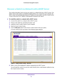
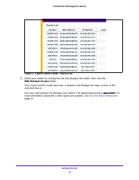
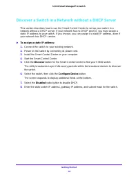
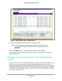
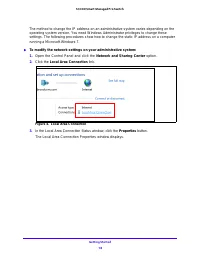
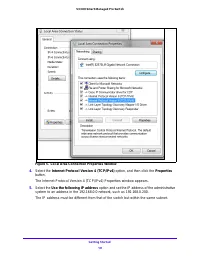
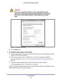
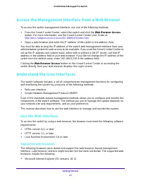
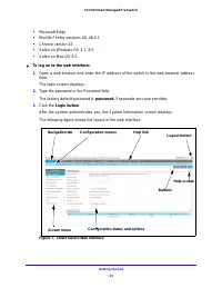
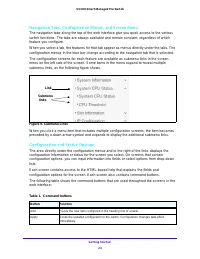
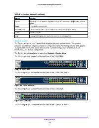
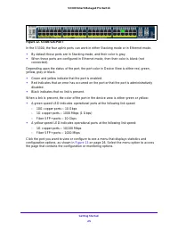
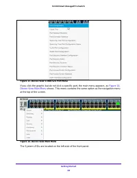
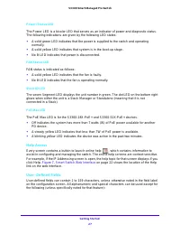
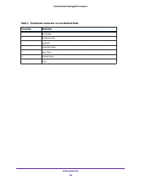
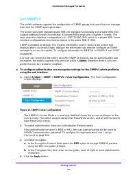
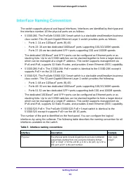
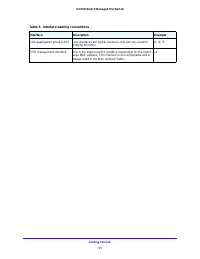
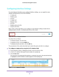
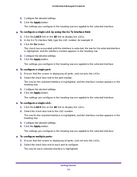
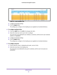
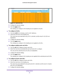
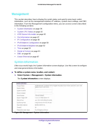
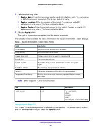
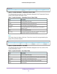
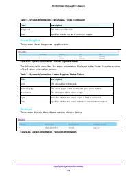
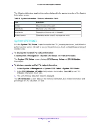
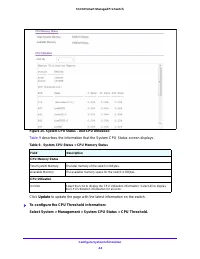
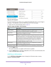
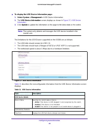
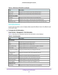
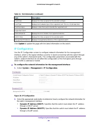
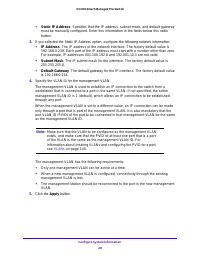
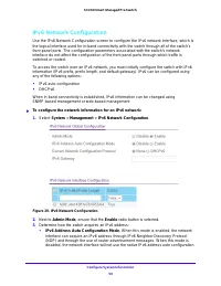
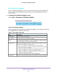
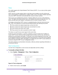
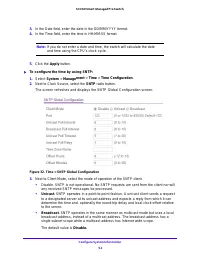
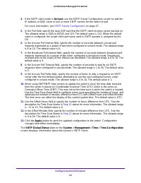
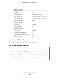
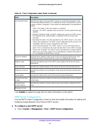
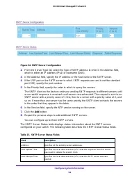
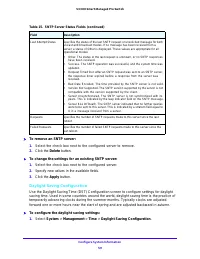
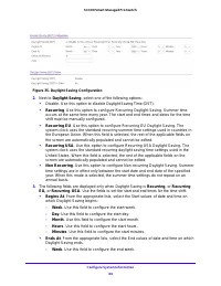

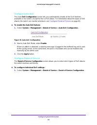

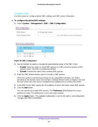
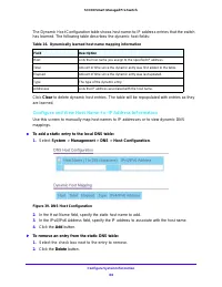
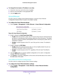
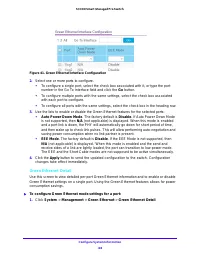
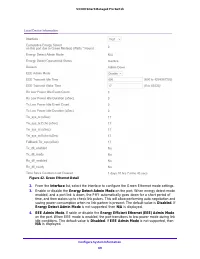
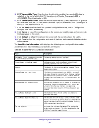
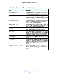
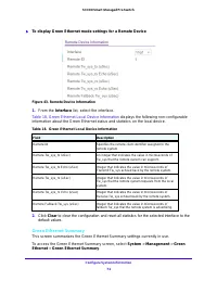
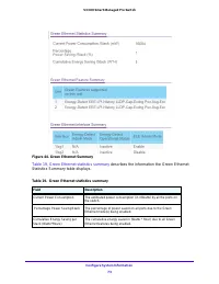
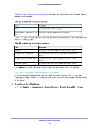
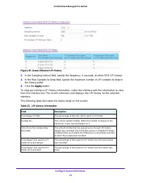
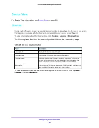
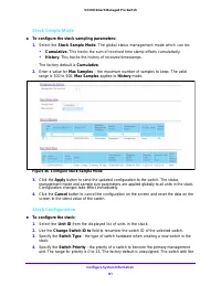
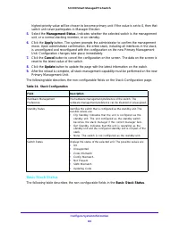
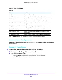
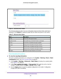
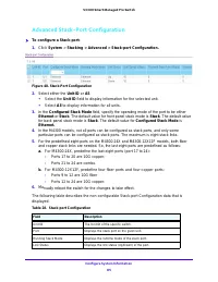
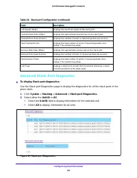
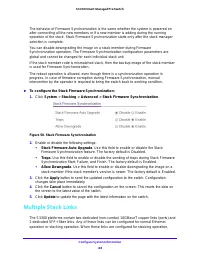

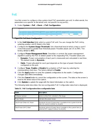
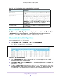

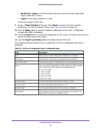
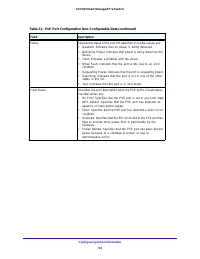
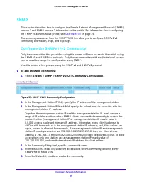
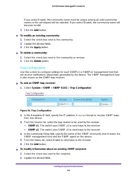
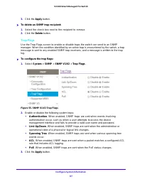
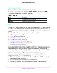
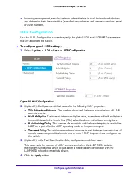
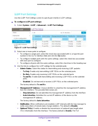
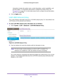
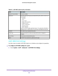
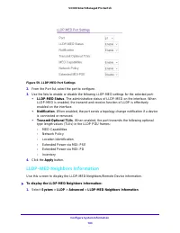
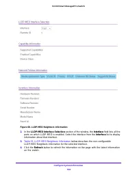
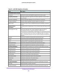
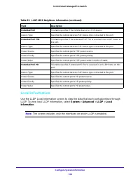
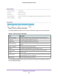
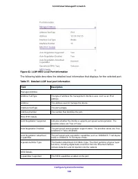
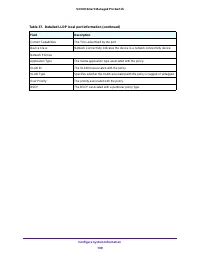
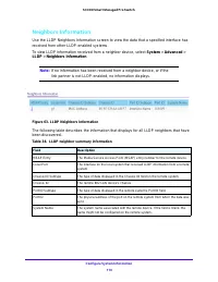
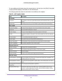
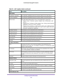
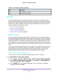
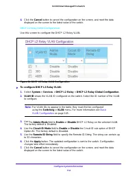
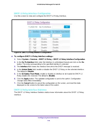
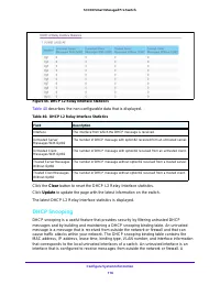
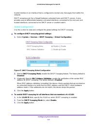
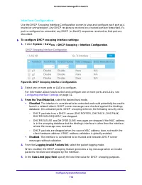
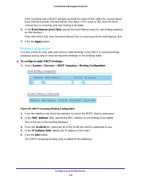
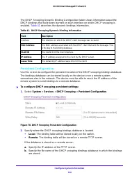
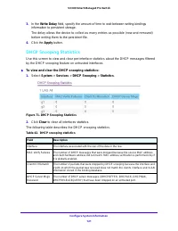
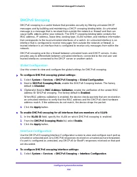
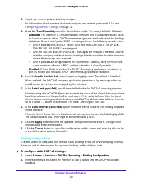
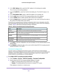
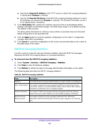
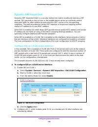
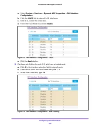
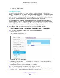
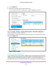
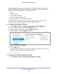
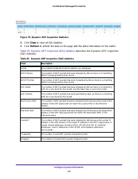
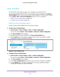
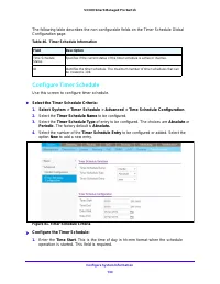

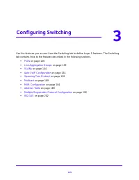
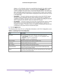
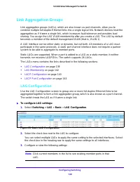
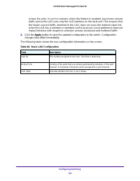
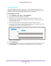
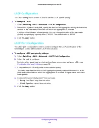
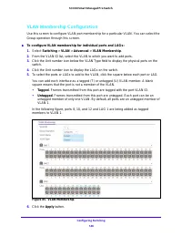

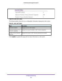
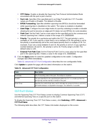
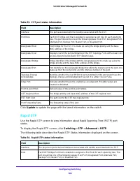

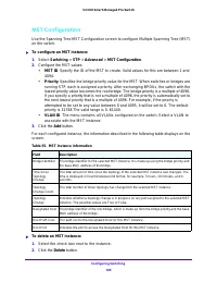
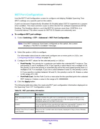
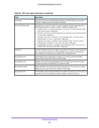
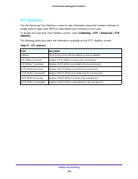
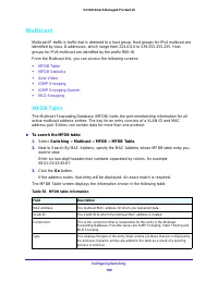
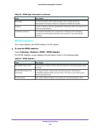
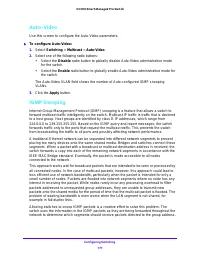
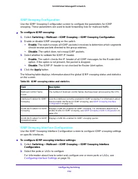
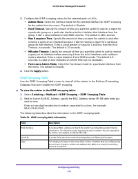
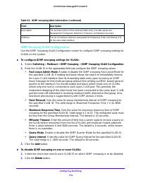
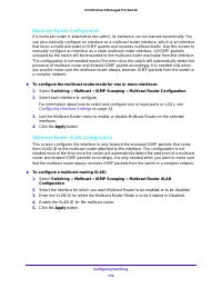
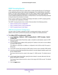
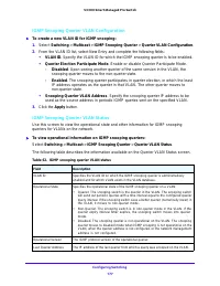
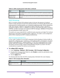
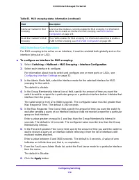
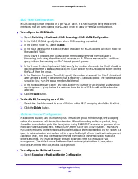
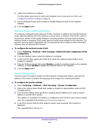
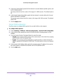
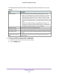
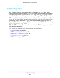
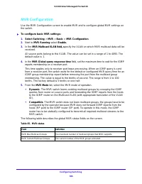
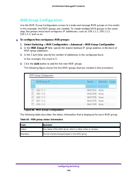
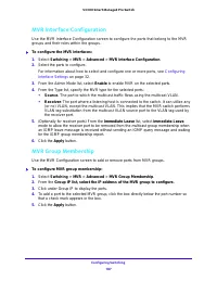
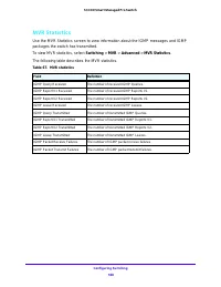
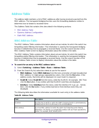
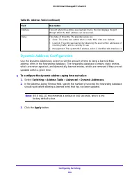
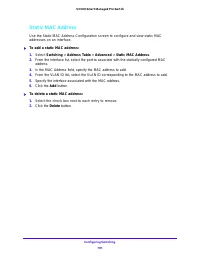
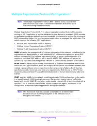
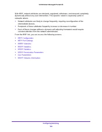
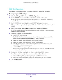
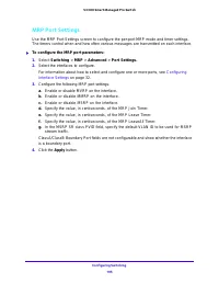
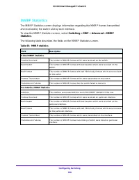
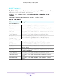
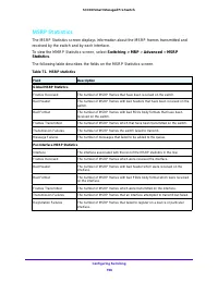
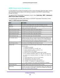
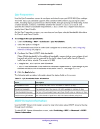
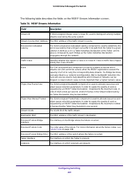
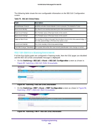
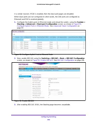
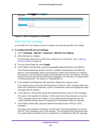
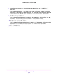
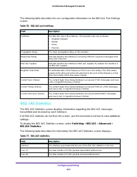
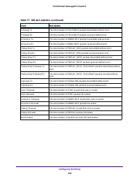
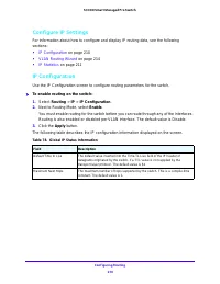
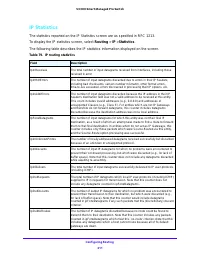
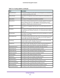
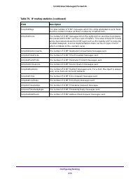
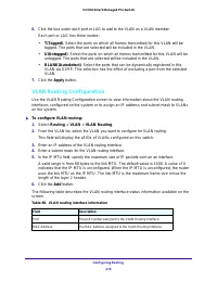
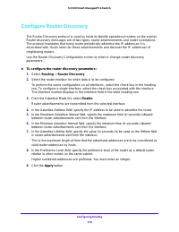
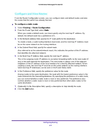
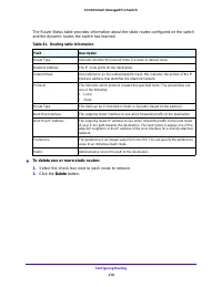
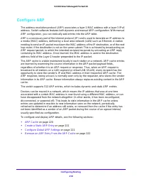
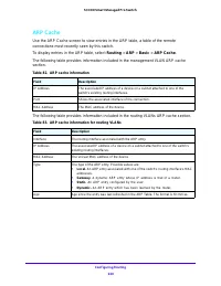
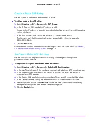
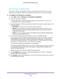
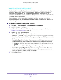

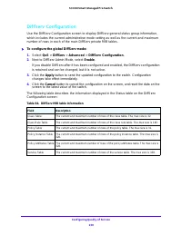
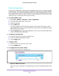
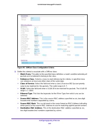
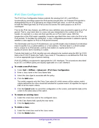
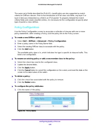
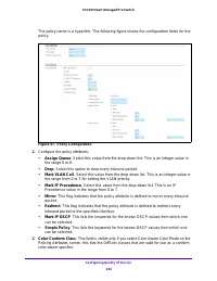
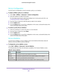

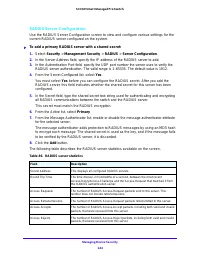
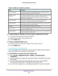
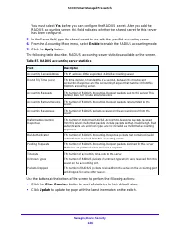
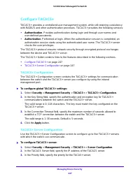
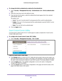
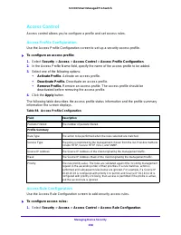
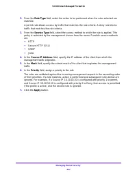
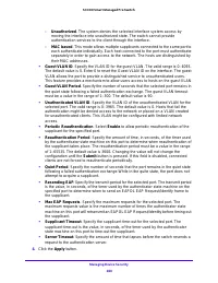
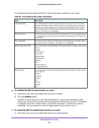
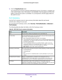
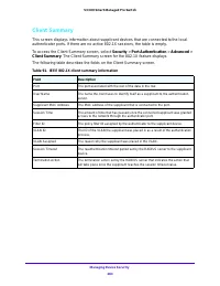
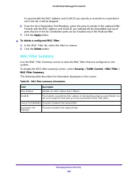
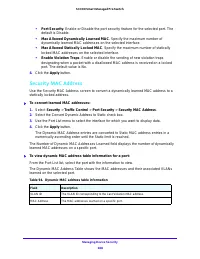
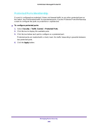
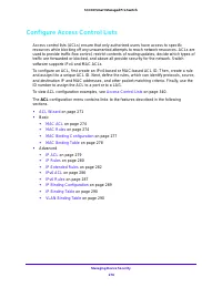
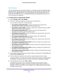
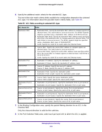
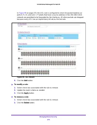
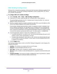
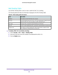
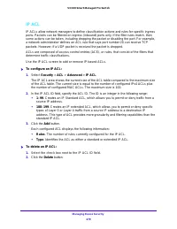
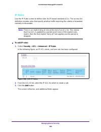
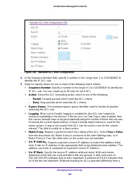
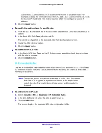
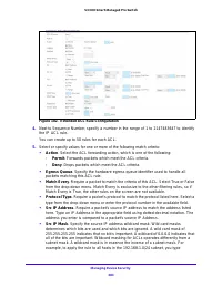

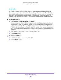
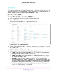
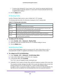


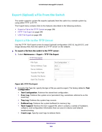
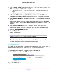
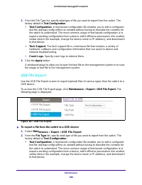
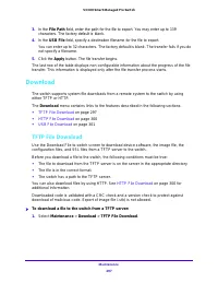
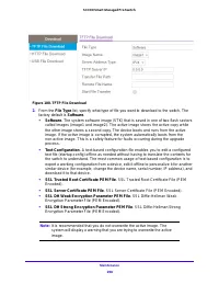
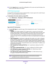
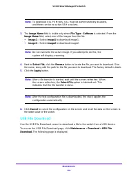
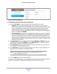
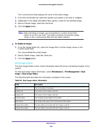
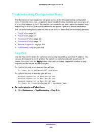
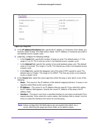

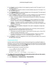
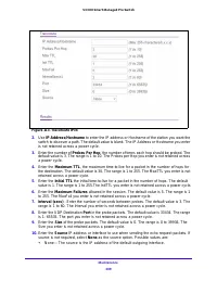


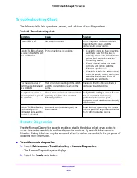
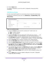
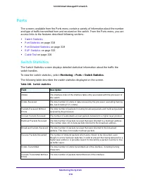

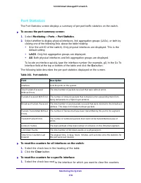
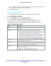
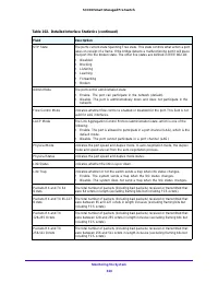
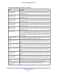
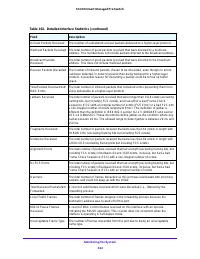
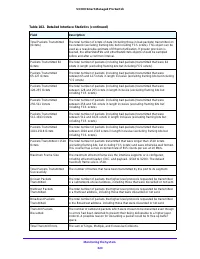
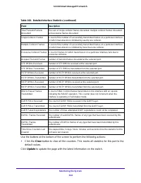
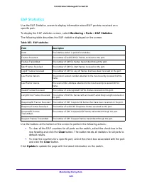
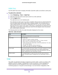
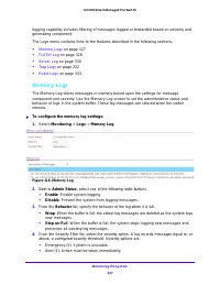
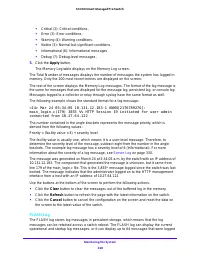
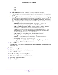
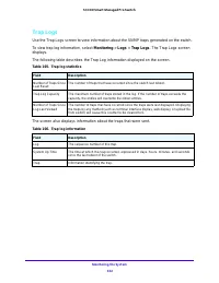
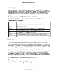
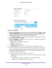
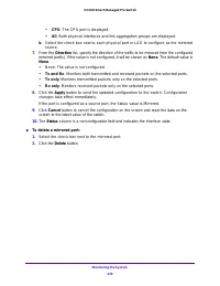
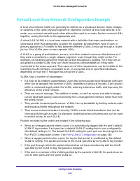
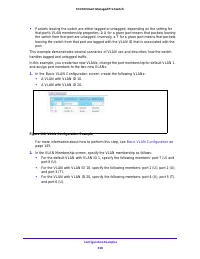
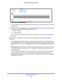

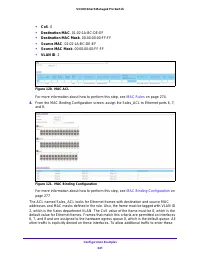
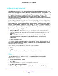
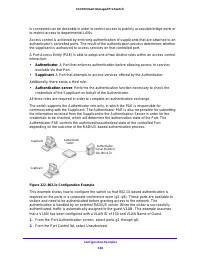
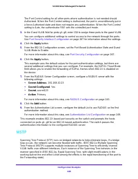
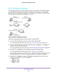
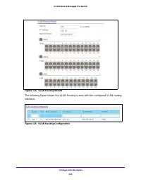
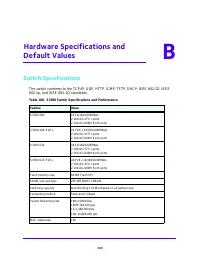
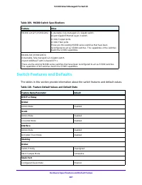
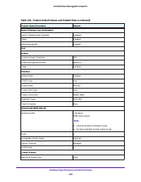
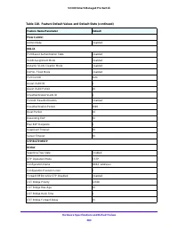
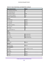
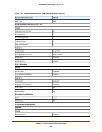
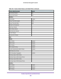
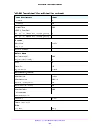
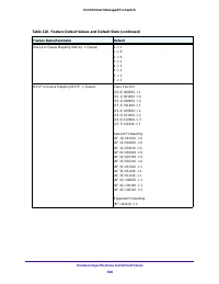
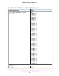
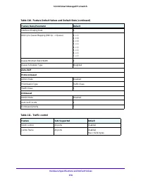
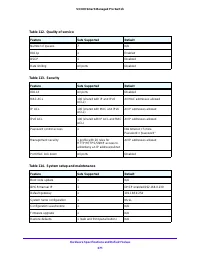

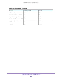
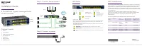 Netgear GS108LP 8xGE PoE
User Manual
Netgear GS108LP 8xGE PoE
User Manual
 Netgear GS110EMX 8x1GE
User Manual
Netgear GS110EMX 8x1GE
User Manual
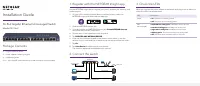 Netgear GS116GE 16xGE
User Manual
Netgear GS116GE 16xGE
User Manual
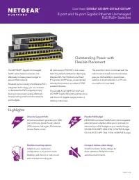 Netgear GS116LP 16x1GE PoE
User Manual
Netgear GS116LP 16x1GE PoE
User Manual
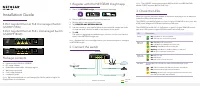 Netgear GS305PP 4xGE PoE
User Manual
Netgear GS305PP 4xGE PoE
User Manual
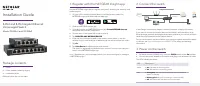 Netgear GS308PP 8xGE PoE
User Manual
Netgear GS308PP 8xGE PoE
User Manual
 Netgear GS316EP 15x1GE PoE
User Manual
Netgear GS316EP 15x1GE PoE
User Manual
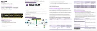 Netgear GS316PP 16xGE PoE
User Manual
Netgear GS316PP 16xGE PoE
User Manual
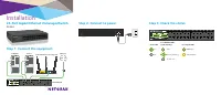 Netgear GS324 24xGE (GS324-200EUS)
User Manual
Netgear GS324 24xGE (GS324-200EUS)
User Manual
 Netgear GS516PP 16xGE PoE
User Manual
Netgear GS516PP 16xGE PoE
User Manual
 Netgear GS524UP 16xGE PoE
User Manual
Netgear GS524UP 16xGE PoE
User Manual
 Netgear GS724T 24xGE, 2xGE SFP
User Manual
Netgear GS724T 24xGE, 2xGE SFP
User Manual
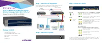 Netgear XS508M 7x100M
User Manual
Netgear XS508M 7x100M
User Manual