Page 3 - Contents
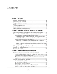
Contents Chapter 1 Hardware Related documentation.......................................................................8Switch package contents.....................................................................8Supported switch models..................................................................
Page 7 - Hardware
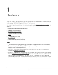
1 Hardware This user manual describes how you can use the device user interface (UI) to configureand manage NETGEAR Gigabit Ethernet Plus Switches. For a list of switch models that this manual supports, see Supported switch models onpage 8. This chapter covers the following topics: • Related documen...
Page 8 - Related documentation; Switch package contents; LEDs
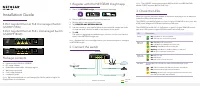
Related documentation Related documentation is available at netgear.com/support/download/: • Installation guide • Data sheet Switch package contents The package contains the switch, AC power adapter (power cable localized to thecountry of sale), and installation guide. Supported switch models The Gi...
Page 10 - Switch label
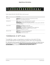
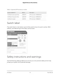
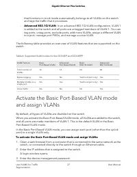
Table 3. Supported SFP transceiver modules Description Model Speed and Medium SFP transceiver 1000BASE-SX AGM731F 1G Ethernet short-reach fiber SFP transceiver 1000BASE-LX AGM732F 1G Ethernet long-reach fiber SFP transceiver 1000BASE-T AGM734 1G Ethernet copper Switch label The switch label on the b...
Page 16 - Discover the IP address and access the switch
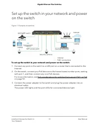
Discover the switch's IP address to access itsdevice UI Use either of the following methods to discover the switch's IP address in your network,and then use the IP address to access the device UI so you can configure and managethe switch. Use a computer and a web browser to discover the switch in yo...
Page 18 - Assign a fixed IP address to the switch; Set a fixed IP address for the switch through a network connection
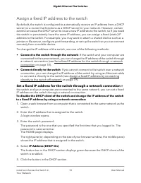
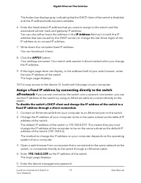
Assign a fixed IP address to the switch By default, the switch is configured to automatically receive an IP address from a DHCPserver (or a router that functions as a DHCP server) in your network. However, certainevents can cause the DHCP server to issue a new IP address to the switch, so if you nee...
Page 21 - Change the language of the device UI; Change the switch password
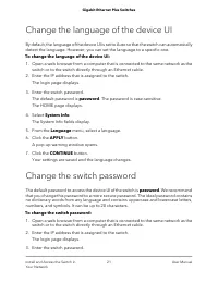
Change the language of the device UI By default, the language of the device UI is set to Auto so that the switch can automaticallydetect the language. However, you can set the language to a specific one. To change the language of the device UI: 1. Open a web browser from a computer that is connected...
Page 22 - Register the switch
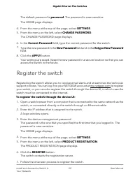
The default password is password. The password is case-sensitive. The HOME page displays. 4. From the menu at the top of the page, select SETTINGS. 5. From the menu on the left, select CHANGE PASSWORD. The CHANGE PASSWORD page displays. 6. In the Current Password field, type the current password for...
Page 23 - Optimize the Switch Performance
3 Optimize the Switch Performance This chapter describes how you can optimize the performance of the switch and containsthe following sections: • Set the quality of service mode and port rate limits • Manage individual port settings 23
Page 24 - Use port-based quality of service and set port priorities
Set the quality of service mode and port ratelimits You can manually set the Quality of Service (QoS) modes to manage traffic: • Port-based QoS mode: Lets you set the priority (low, medium, high, or critical) forindividual port numbers and lets you set rate limits for incoming and outgoing trafficfo...
Page 29 - Manage individual port settings; Set rate limits for a port
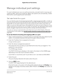
Manage individual port settings For each individual port, you can set the port priority, set rate limits for incoming andoutgoing traffic, set the port speed (by default, the speed is set automatically), enableflow control, and change the port name label. Set rate limits for a port You can limit the...
Page 30 - Set the priority for a port
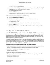
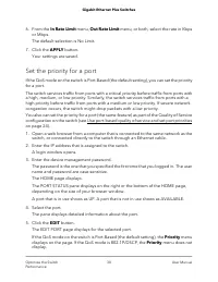
6. From the In Rate Limit menu, Out Rate Limit menu, or both, select the rate in Kbps or Mbps.The default selection is No Limit. 7. Click the APPLY button. Your settings are saved. Set the priority for a port If the QoS mode on the switch is Port-Based (the default setting), you can set the priority...
Page 31 - Manage flow control for a port
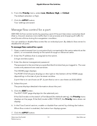
6. From the Priority menu, select Low, Medium, High, or Critical. The default selection is High. 7. Click the APPLY button. Your settings are saved. Manage flow control for a port IEEE 802.3x flow control works by pausing a port if the port becomes oversubscribed(that is, the port receives more traf...
Page 32 - Change the speed for a port or disable a port
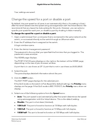
Your settings are saved. Change the speed for a port or disable a port By default, the port speed on all ports is set automatically (that is, the setting is Auto)after the switch determines the speed using autonegotiation with the linked device. Werecommend that you leave the Auto setting for the po...
Page 33 - Add or change the name label for a port
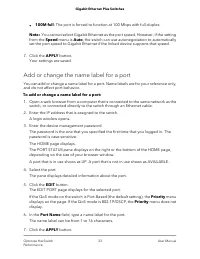
• 100M full: The port is forced to function at 100 Mbps with full-duplex. Note: You cannot select Gigabit Ethernet as the port speed. However, if the settingfrom the Speed menu is Auto, the switch can use autonegotiation to automaticallyset the port speed to Gigabit Ethernet if the linked device sup...
Page 35 - Use VLANS for Traffic Segmentation
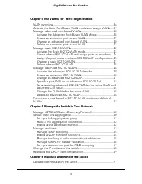
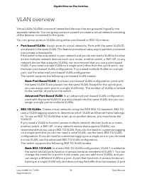
4 Use VLANS for Traffic Segmentation This chapter describes how you can use VLANs to segment traffic on the switchj, andcontains these sections: • VLAN overview • Activate the Basic Port-Based VLAN mode and assign VLANs • Manage advanced port-based VLANs • Manage basic 802.1Q VLANs • Manage advanced...
Page 38 - Manage advanced port-based VLANs; Activate the Advanced Port-Based VLAN Mode
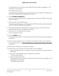
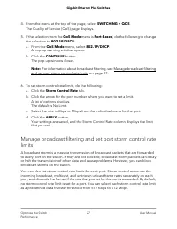
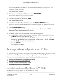
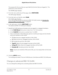
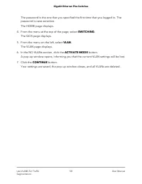
The password is the one that you specified the first time that you logged in. Thepassword is case-sensitive. The HOME page displays. 4. From the menu at the top of the page, select SWITCHING. The Quality of Service (QOS) page displays. 5. From the menu on the left, select VLAN. The VLAN page display...
Page 39 - Create an advanced port-based VLAN
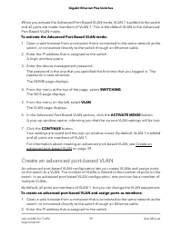
When you activate the Advanced Port-Based VLAN mode, VLAN 1 is added to the switchand all ports are made members of VLAN 1. This is the default VLAN in the AdvancedPort-Based VLAN mode. To activate the Advanced Port-Based VLAN mode: 1. Open a web browser from a computer that is connected to the same...
Page 40 - Change an advanced port-based VLAN
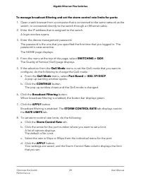
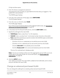
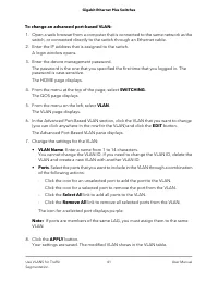
A login window opens. 3. Enter the device management password. The password is the one that you specified the first time that you logged in. Thepassword is case-sensitive. The HOME page displays. 4. From the menu at the top of the page, select SWITCHING. The QOS page displays. 5. From the menu on th...
Page 42 - Delete an advanced port-based VLAN
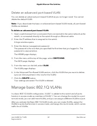
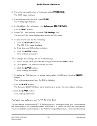
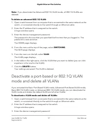
Delete an advanced port-based VLAN You can delete an advanced port-based VLAN that you no longer need. You cannotdelete the default VLAN. Note: If you deactivate the basic or advanced port-based VLAN mode, all port-basedVLANs are deleted. To delete an advanced port-based VLAN: 1. Open a web browser ...
Page 43 - Activate the Basic 802.1Q VLAN mode
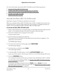
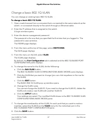
For more information about basic 802.1Q VLANs, see the following sections: • Activate the Basic 802.1Q VLAN mode • Create a basic 802.1Q VLAN and assign ports as members • Assign the port mode in a basic 802.1Q VLAN configuration • Change a basic 802.1Q VLAN • Delete a basic 802.1Q VLAN Activate the...
Page 44 - Create a basic 802.1Q VLAN and assign ports as members
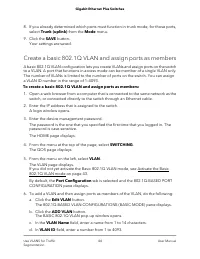
8. If you already determined which ports must function in trunk mode, for those ports, select Trunk (uplink) from the Mode menu. 9. Click the SAVE button. Your settings are saved. Create a basic 802.1Q VLAN and assign ports as members A basic 802.1Q VLAN configuration lets you create VLANs and assig...
Page 45 - Assign the port mode in a basic 802.1Q VLAN configuration
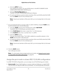
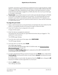
e. Click the APPLY button. Your settings are saved. The new VLAN shows in the 802.1Q-BASED VLANCONFIGURATIONS (BASIC MODE) pane. f. Click the Port Configuration tab. The 802.1Q PORT CONFIGURATIONS pane displays g. For each port that you want to make a member of the new VLAN, select the VLAN from the...
Page 48 - Manage advanced 802.1Q VLANs
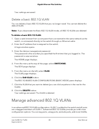
Your settings are saved. Delete a basic 802.1Q VLAN You can delete a basic 802.1Q VLAN that you no longer need. You cannot delete thedefault VLAN. Note: If you deactivate the Basic 802.1Q VLAN mode, all 802.1Q VLANs are deleted. To delete a basic 802.1Q VLAN: 1. Open a web browser from a computer th...
Page 49 - Activate the advanced 802.1Q VLAN mode
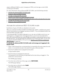
assign a different VLAN to a port, manage port PVIDs, and manage a voice VLAN,including the OUI table. For more information about advanced 802.1Q VLANs, see the following sections: • Activate the advanced 802.1Q VLAN mode • Create an advanced 802.1Q VLAN • Change an advanced 802.1Q VLAN • Specify a ...
Page 50 - Create an advanced 802.1Q VLAN
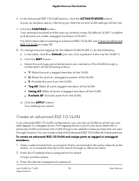
6. In the Advanced 802.1Q VLAN section, click the ACTIVATE MODE button. A pop-up window opens, informing you that the current VLAN settings will be lost. 7. Click the CONTINUE button. Your settings are saved and the pop-up window closes. By default, VLAN 1 is addedand all ports are made untagged mem...
Page 51 - Change an advanced 802.1Q VLAN
The password is the one that you specified the first time that you logged in. Thepassword is case-sensitive. The HOME page displays. 4. From the menu at the top of the page, select SWITCHING. The QOS page displays. 5. From the menu on the left, select VLAN. The VLAN page displays.If you did not yet ...
Page 53 - Specify a port PVID for an advanced 802.1Q VLAN
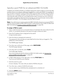
Specify a port PVID for an advanced 802.1Q VLAN A default port VLAN ID (PVID) is a VLAN ID tag that the switch assigns to incoming datapackets that are not already addressed (tagged) for a particular VLAN. For example, ifyou connect a computer to port 6 of the switch and you want it to be a part of ...
Page 55 - Change the OUI table for the voice VLAN
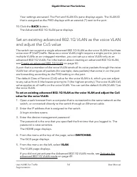
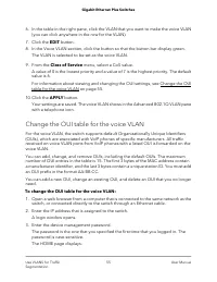
6. In the table in the right pane, click the VLAN that you want to make the voice VLAN (you can click anywhere in the row for the VLAN). 7. Click the EDIT button. 8. In the Voice VLAN section, click the button so that the button bar display green. The VLAN is selected to be set as the voice VLAN. 9....
Page 56 - Delete an advanced 802.1Q VLAN
4. From the menu at the top of the page, select SWITCHING. The QOS page displays. 5. From the menu on the left, select VLAN. The VLAN page displays. 6. In the table in the right pane, click Advanced 802.1Q VLAN. 7. Click the EDIT button. 8. In the OUI Table section, click the OUI Settings link. The ...
Page 59 - Manage the Switch in Your Network
5 Manage the Switch in Your Network This chapter describes how you can manage the switch in your network. The chapter contains the following sections: • Manage NETGEAR Switch Discovery Protocol • Set up static link aggregation • Manage multicast • Change the IP address of the switch • Reenable the D...
Page 61 - Set up a link aggregation group
Set up static link aggregation on the switch by performing this series of tasks: 1. Set up the LAG on the switch (see Set up a link aggregation group on page 61). 2. Connect the ports that must be members of the LAG on the switch to the ports that must be members of the LAG on another device in your...
Page 62 - Make a link aggregation connection; Enable a link aggregation group
7. Click the APPLY button. Your settings are saved. Now that the LAG ports are selected, you must set up the physical link aggregationconnection. For more information, see Make a link aggregation connection on page62. Make a link aggregation connection Before you make a physical link aggregation con...
Page 63 - Manage multicast
To enable a LAG on the switch: 1. Open a web browser from a computer that is connected to the same network as the switch, or connected directly to the switch through an Ethernet cable. 2. Enter the IP address that is assigned to the switch. A login window opens. 3. Enter the device management passwo...
Page 64 - Manage IGMP snooping; Enable a VLAN for IGMP snooping
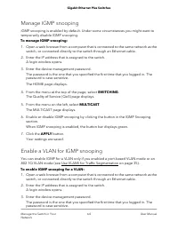
Manage IGMP snooping IGMP snooping is enabled by default. Under some circumstances you might want totemporarily disable IGMP snooping. To manage IGMP snooping: 1. Open a web browser from a computer that is connected to the same network as the switch, or connected directly to the switch through an Et...
Page 65 - Manage blocking of unknown multicast addresses
The HOME page displays. 4. From the menu at the top of the page, select SWITCHING > QOS . The Quality of Service (QoS) page displays. 5. From the menu on the left, select MULTICAST. The MULTICAST page displays. 6. In the VLAN ID Enabled for IGMP Snooping section, enter a VLAN ID in the field. If ...
Page 66 - Manage IGMPv3 IP header validation
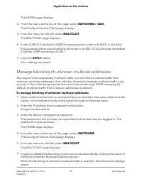
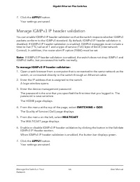
7. Click the APPLY button. Your settings are saved. Manage IGMPv3 IP header validation You can enable IGMPv3 IP header validation so that the switch inspects whether IGMPv3packets conform to the IGMPv3 standard. By default, IGMPv3 IP header validation isdisabled. If IGMPv3 IP header validation is en...
Page 67 - Set up a static router port for IGMP snooping
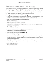
Set up a static router port for IGMP snooping If your network does not include a device that sends IGMP queries, the switch cannotdiscover the router port dynamically. (The router port is a port on a device in the networkthat performs IGMP snooping in the network.) In this situation, select one port...
Page 68 - Change the IP address of the switch
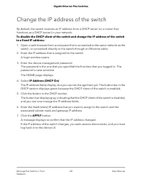
Change the IP address of the switch By default, the switch receives an IP address from a DHCP server (or a router thatfunctions as a DHCP server) in your network. To disable the DHCP client of the switch and change the IP address of the switchto a fixed IP address: 1. Open a web browser from a compu...
Page 69 - Reenable the DHCP client of the switch
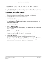
Reenable the DHCP client of the switch If you disabled the DHCP client of the switch and changed the IP address of the switchto a fixed (static) IP address, you can reverse the situation. To reenable the DHCP client on the switch: 1. Open a web browser from a computer that is connected to the same n...
Page 70 - Maintain and Monitor the Switch
6 Maintain and Monitor the Switch This chapter describes how you can maintain and monitor the switch, and contains thesesections: • Update the firmware on the switch • Manage the configuration file • Return the switch to its factory default settings • Control access to the device UI • HTTP and HTTPS...
Page 71 - Update the firmware on the switch
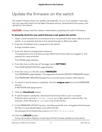
Update the firmware on the switch The switch firmware does not update automatically, so you must update it manually.You can manually check for the latest firmware version, download the firmware, andupload it to the switch. CAUTION: Always read the release notes before updating the switch's firmware....
Page 72 - Manage the configuration file; Back up the switch configuration
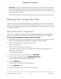
WARNING: Do not interrupt the network connection or power to the switch during the firmware update process. Do not disconnect any Ethernet cables or power offthe switch until the firmware update process and switch reboot are complete. Doingso can damage the switch. Your switch web session is disconn...
Page 73 - Restore the switch configuration
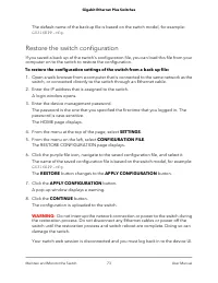
The default name of the backup file is based on the switch model, for example: GS316EPP.cfg . Restore the switch configuration If you saved a back up of the switch's configuration file, you can load this file from yourcomputer on to the switch to restore the configuration. To restore the configurati...
Page 74 - Use the RESET button to reset the switch
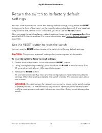
Return the switch to its factory defaultsettings You can reset the switch to return it to factory default settings, using either the RESETbutton on the front of the switch, or the reset function in the device UI. If you have lostthe password and cannot access the switch, you must use the RESET butto...
Page 75 - Use the device UI to reset the switch; Control access to the device UI
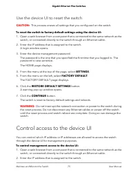
Use the device UI to reset the switch CAUTION: This process erases all settings that you configured on the switch. To reset the switch to factory default settings using the device UI: 1. Open a web browser from a computer that is connected to the same network as the switch, or connected directly to ...
Page 76 - HTTP and HTTPS management access
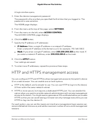
A login window opens. 3. Enter the device management password. The password is the one that you specified the first time that you logged in. Thepassword is case-sensitive. The HOME page displays. 4. From the menu at the top of the page, select SETTINGS. 5. From the menu on the left, select ACCESS CO...
Page 77 - Configure HTTP access settings; Browser security message with HTTPS access
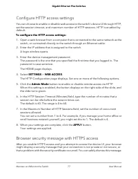
Configure HTTP access settings You can choose to enable or disable web access to the switch's device UI through HTTP,set the session timeout, and maximum number of HTTP sessions. HTTP is enabled bydefault. To configure the HTTP access settings: 1. Open a web browser from a computer that is connected...
Page 78 - Configure HTTPS access settings
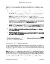
Note: To avoid encountering a security message again, you can configure an SSLcertificate. For more information, see Manage certificates for HTTPS access on page79. If a security message displays, you cannot proceed but must take one of the followingactions, depending on the browser that you are usi...
Page 79 - Manage certificates for HTTPS access
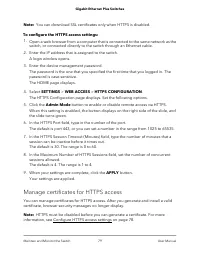
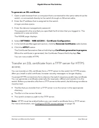
Note: You can download SSL certificates only when HTTPS is disabled. To configure the HTTPS access settings: 1. Open a web browser from a computer that is connected to the same network as the switch, or connected directly to the switch through an Ethernet cable. 2. Enter the IP address that is assig...
Page 81 - Delete certificates for HTTPS access
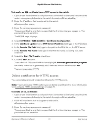
To transfer an SSL certificate from a TFTP server to the switch: 1. Open a web browser from a computer that is connected to the same network as the switch, or connected directly to the switch through an Ethernet cable. 2. Enter the IP address that is assigned to the switch. A login window opens. 3. ...
Page 82 - Change or lift access restrictions to the switch
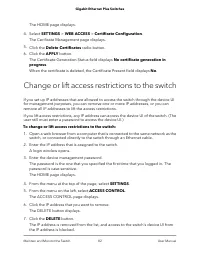
The HOME page displays. 4. Select SETTINGS > WEB ACCESS > Certificate Configuration. The Cerificate Management page displays. 5. Click the Delete Certificates radio button. 6. Click the APPLY button. The Certificate Generation Status field displays No certificate generation inprogress. When th...
Page 83 - Manage the DoS prevention mode; Manage the power saving mode
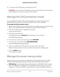
8. To remove more IP addresses, repeat steps 6 and 7. CAUTION: If you remove all IP addresses, all access restrictions are removed and any IP address can access the device UI of the switch. Manage the DoS prevention mode You can enable the Denial of Service (DoS) prevention mode so that the switchau...
Page 84 - Control the port LEDs
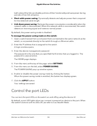
both sides of the link can disable portions of their functionality and save power duringperiods of low link utilization. • Short cable power saving: Dynamically detects and adjusts power that is requiredfor the detected cable length. • Link-down power saving: Reduces the power consumption considerab...
Page 85 - Change the switch device name
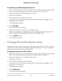
To control the port LEDs through the device UI: 1. Open a web browser from a computer that is connected to the same network as the switch, or connected directly to the switch through an Ethernet cable. 2. Enter the IP address that is assigned to the switch. A login window opens. 3. Enter the device ...
Page 86 - View system information; Date and time settings; Configure the system time manually
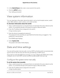
5. In the Switch Name field, enter a new name for the switch. 6. Click the APPLY button. Your settings are saved. View system information You can view basic information about the switch, such as the firmware version, switchname, MAC address, serial number, and model number. To view basic information...
Page 87 - Configure the SNTP client mode
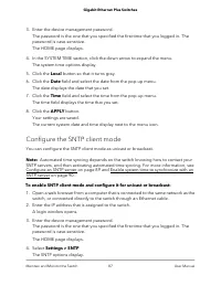
3. Enter the device management password. The password is the one that you specified the first time that you logged in. Thepassword is case-sensitive. The HOME page displays. 4. In the SYSTEM TIME section, click the down arrow to expand the menu. The system time options display. 5. Click the Local bu...
Page 89 - Configure an SNTP server
Configure an SNTP server You can enable automatic syncing of system time after you configure at least one SNTPserver providing you also: • Configure the SNTP client mode to use either a public SNTP server, or a clock andSNTP server within your own network. For more information, see Configure the SNT...
Page 90 - Enable system time to synchronize with an SNTP server
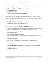
11. In the Priority field, set a priority from 1 to 3, with the lowest number assigned to the preferred SNTP server. 12. In the Version field, set the SNTP version from 1 to 4. 13. Click the APPLY button. Your settings are saved. The SNTP server information displays in a table. Enable system time to...
Page 91 - View switch connections; View the status of a port
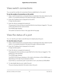
View switch connections You can see the number of connections that are established on the switch. To see the number of connections on the switch: 1. Open a web browser from a computer that is connected to the same network as the switch, or connected directly to the switch through an Ethernet cable. ...
Page 92 - Power over Ethernet; PoE considerations for switches that support PoE+ or PoE
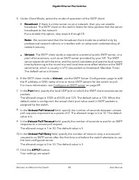
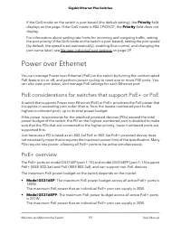
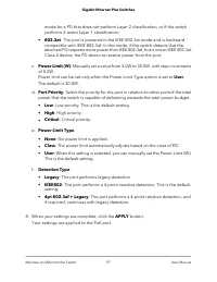
If the QoS mode on the switch is port-based (the default setting), the Priority fielddisplays on the page. If the QoS mode is 802.1P/DSCP, the Priority field does notdisplay. For information about setting rate limits for incoming and outgoing traffic, settingthe port priority (if the QoS mode on the...
Page 93 - Monitor PD health
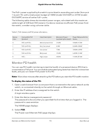
The PoE+ power supplied by the switch is prioritized in ascending port order (from port1 to port 15), with a total power budget of 180W (model GS316EP) or 231W (modelGS316EPP) across all active PoE+ ports. The following table shows the standard power ranges, calculated with the maximumcable length o...
Page 94 - Manage uninterrupted PoE
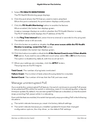
5. Select PD HEALTH MONITORING. The PD Health Monitoring page displays. 6. Click the port where the PD that you want to test is attached. When the port is selected, the port button displays solid purple. 7. Click the PD Health Monitoring button to enable the feature. When enabled, the button bar dis...
Page 95 - Power cycle the PoE ports
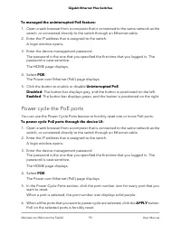
To managed the uninterrupted PoE feature: 1. Open a web browser from a computer that is connected to the same network as the switch, or connected directly to the switch through an Ethernet cable. 2. Enter the IP address that is assigned to the switch. A login window opens. 3. Enter the device manage...
Page 96 - Manage an individual PoE port
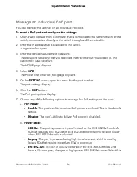
Manage an individual PoE port You can manage the settings on an individual PoE port. To select a PoE port and configure the settings: 1. Open a web browser from a computer that is connected to the same network as the switch, or connected directly to the switch through an Ethernet cable. 2. Enter the...
Page 98 - Display PoE port status
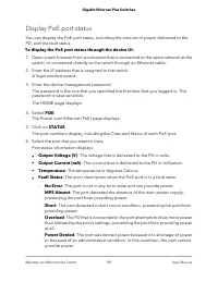
Display PoE port status You can display the PoE port status, including the amount of power delivered to thePD, and the fault status. To display the PoE port status through the device UI: 1. Open a web browser from a computer that is connected to the same network as the switch, or connected directly ...
Page 99 - Configure a PoE schedule
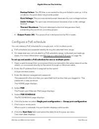
- Startup Failure: The PD that is connected to the port failed to start up. In thiscondition, the port does not provide power. - Over Voltage: The port was denied power because of a over-voltage lockout. - Under Voltage: The port was denied power because of an under-voltagelockout. - Thermal Shutdow...
Page 100 - Edit or disable a PoE schedule
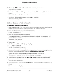
9. Click the End Date field and select the date from the pop-up menu. Your end date displays. 10. For each day of the week that you want to schedule PoE, use the sliders to set the ranges.Green indicates that PoE is enabled. 11. When your settings are complete, click the APPLY button. The schedule i...
Page 102 - Diagnostics and Troubleshooting
7 Diagnostics and Troubleshooting This chapter covers the following topics: • Test cable connections • Resolve a subnet conflict to access the switch • PoE troubleshooting suggestions 102
Page 103 - Test cable connections; Resolve a subnet conflict to access the switch
Test cable connections You can use the cable diagnostic feature to easily find out the health status of networkcables. If any problems exist, this feature helps quickly locate the point where the cablingfails, allowing connectivity issues to be fixed much faster, potentially saving technicianshours ...
Page 104 - PoE troubleshooting suggestions
be different from the subnet used in your network. You might see the following messageif you try to access the switch: The switch and manager IP address are not in the same subnet. To resolve this subnet conflict: 1. Disconnect the Ethernet cable between the switch and your network. 2. Shut down pow...
Page 106 - Factory default settings
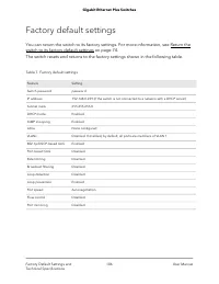
Factory default settings You can return the switch to its factory settings. For more information, see Return theswitch to its factory default settings on page 74. The switch resets and returns to the factory settings shown in the following table. Table 7. Factory default settings Setting Feature pas...
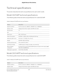
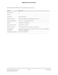
Page 107 - Technical specifications; Model GS316EP technical specifications; Model GS316EPP technical specifications
Technical specifications This section describes the technical specifications for each switch model. Model GS316EP technical specifications The following table shows the technical specifications for model GS316EP. Table 8. Models GS316EP technical specifications Description Feature RJ-45 connector fo...
Page 110 - Access the switch from any computer
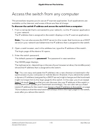
Access the switch from any computer This procedure requires you to use an IP scanner application. Such applications areavailable on the Internet, and some of them are free of charge. To discover the switch IP address and access the switch from a computer: 1. From a computer that is connected to your...


 Netgear GS108LP 8xGE PoE
User Manual
Netgear GS108LP 8xGE PoE
User Manual
 Netgear GS110EMX 8x1GE
User Manual
Netgear GS110EMX 8x1GE
User Manual
 Netgear GS116GE 16xGE
User Manual
Netgear GS116GE 16xGE
User Manual
 Netgear GS116LP 16x1GE PoE
User Manual
Netgear GS116LP 16x1GE PoE
User Manual
 Netgear GS305PP 4xGE PoE
User Manual
Netgear GS305PP 4xGE PoE
User Manual
 Netgear GS308PP 8xGE PoE
User Manual
Netgear GS308PP 8xGE PoE
User Manual
 Netgear GS316PP 16xGE PoE
User Manual
Netgear GS316PP 16xGE PoE
User Manual
 Netgear GS324 24xGE (GS324-200EUS)
User Manual
Netgear GS324 24xGE (GS324-200EUS)
User Manual
 Netgear GS516PP 16xGE PoE
User Manual
Netgear GS516PP 16xGE PoE
User Manual
 Netgear GS524UP 16xGE PoE
User Manual
Netgear GS524UP 16xGE PoE
User Manual
 Netgear GS724T 24xGE, 2xGE SFP
User Manual
Netgear GS724T 24xGE, 2xGE SFP
User Manual
 Netgear S3300-28X (GS728TX) 24x1GE
User Manual
Netgear S3300-28X (GS728TX) 24x1GE
User Manual
 Netgear XS508M 7x100M
User Manual
Netgear XS508M 7x100M
User Manual