Page 4 - Contents
Contents Chapter 1 Hardware Overview of the Switch Related documentation.......................................................................8Switch package contents.....................................................................8Front panel.......................................................
Page 7 - Hardware Overview of the Switch
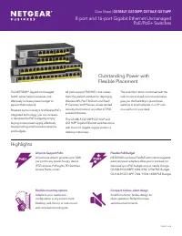
1 Hardware Overview of the Switch The NETGEAR 8-Port Gigabit Ethernet Plus Switch with 2-Port 10G/Multi-Gig UplinksModel GS110EMX, in this manual referred to as the switch, is intended for small andmedium-sized business networks and home offices that require high-speed uplinks. Inaddition to the eig...
Page 9 - Front panel
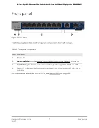
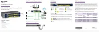
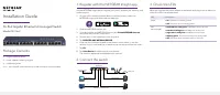
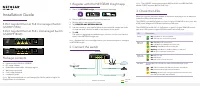
Front panel Figure 2. Front panel The following table lists the front panel components from left to right. Table 1. Front panel components Description Letter Power LED A Factory Defaults button (see Use the Factory Defaults button to reset the switch on page 64) B Eight RJ-45 Gigabit Ethernet ports ...
Page 10 - Status LEDs
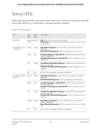
Status LEDs Status LEDs are located on the front panel of the switch. Each port provides a left LEDand a right LED that, in combination, indicate speed and activity. Table 2. LED descriptions Description RightLED LeftLED LED Off. No power is supplied to the switch.Solid green. Power is supplied to t...
Page 11 - Safety instructions and warnings
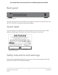
Back panel Figure 3. Back panel The back panel of the switch provides a Kensington lock slot for an optional lock andthe 12V, 12.5A DC connector for the power adapter. Switch label The switch label on the bottom panel of the switch shows the serial number, MACaddress, default login information, and ...
Page 18 - Access the switch from a Windows-based computer
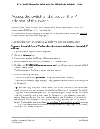
Access the switch and discover the IPaddress of the switch By default, the switch receives an IP address from a DHCP server (or a router thatfunctions as a DHCP server) in your network. For information about setting up a fixed (static) IP address on the switch, see Set up afixed IP address for the s...
Page 19 - Access the switch from a Mac using Bonjour
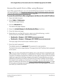
Access the switch from a Mac using Bonjour If your Mac supports Bonjour, you can use the following procedure. If your Mac doesnot support Bonjour, see Access the switch from a Mac or Windows-based computerusing the NETGEAR Switch Discovery Tool on page 20. To access the switch from a Mac using Bonjo...
Page 21 - Set up a fixed IP address for the switch
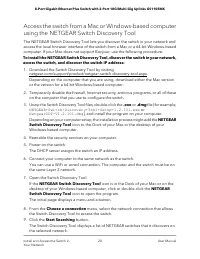
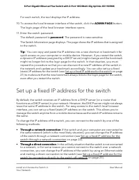
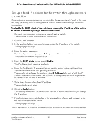
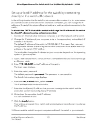
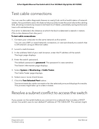
For each switch, the tool displays the IP address. 10. To access the local browser interface of the switch, click the ADMIN PAGE button. The login page of the local browser interface opens. 11. Enter the switch password. The default password is password. The password is case-sensitive. The Switch In...
Page 24 - Change the switch password
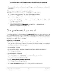
For more information, see Set up the switch in your network and power on the switchon page 16. 11. Restore your computer to its original IP address. 12. Verify that you can connect to the switch with its new IP address: a. Connect your computer to the same network as the switch. You can use a WiFi o...
Page 25 - Register your product
7. Type the new password in the New Password field and in the Re-type New Password field. 8. Click the Apply button. Your settings are saved. Keep the new password in a secure location so that you canaccess the switch in the future. Register your product Registering your product allows you to receiv...
Page 26 - Use VLANS for Traffic Segmentation
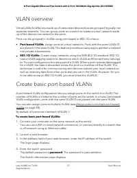
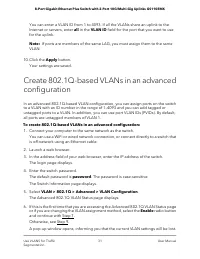
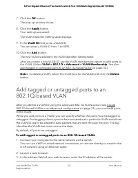
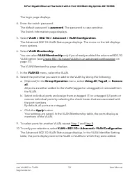
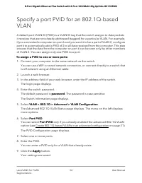
3 Use VLANS for Traffic Segmentation This chapter describes how you can use VLANs to segment traffic on the switch. The chapter contains the following sections: • VLAN overview • Create basic port-based VLANs • Assign ports to multiple port-based VLANs • Create 802.1Q-based VLANs in a basic configur...
Page 28 - Assign ports to multiple port-based VLANs
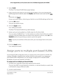
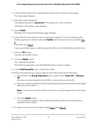
5. Select VLAN. The Basic Port-based VLAN Status page displays. 6. If this is the first time that you are accessing this page or if you are changing the VLAN assignment method, select the Enable radio button and continue with Step7.Otherwise, see Step 9. A pop-up window opens, informing you that the...
Page 35 - Manage the voice VLAN; Specify the voice VLAN properties
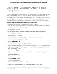
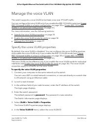
Manage the voice VLAN The switch supports a voice VLAN to facilitate voice over IP (VoIP) traffic. You can configure the voice VLAN only if you enable the 802.1Q VLAN mode (see Create802.1Q-based VLANs in a basic configuration on page 30 or Create 802.1Q-basedVLANs in an advanced configuration on pa...
Page 36 - Enable the voice VLAN mode for ports
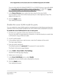
You can select either the default VLAN ID (1) or a VLAN ID that you manually added(see Create 802.1Q-based VLANs in a basic configuration on page 30 or Create802.1Q-based VLANs in an advanced configuration on page 31). 7. In the Class of Service menu, select the class value for the voice VLAN. You c...
Page 37 - Manage the OUI table
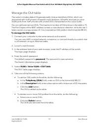
Manage the OUI table The switch includes default Organizationally Unique Identifiers (OUIs), which areassociated with VoIP phones of specific manufacturers. All traffic received on voiceVLAN ports from VoIP phones with a listed OUI is forwarded on the voice VLAN. You can add and remove OUIs. The max...
Page 40 - Configure port-based quality of service
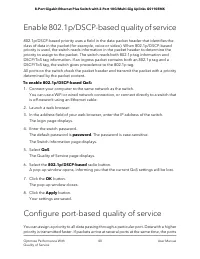
Enable 802.1p/DSCP-based quality of service 802.1p/DSCP-based priority uses a field in the data packet header that identifies theclass of data in the packet (for example, voice or video). When 802.1p/DSCP-basedpriority is used, the switch reads information in the packet header to determine thepriori...
Page 42 - Set up rate limiting; Set up broadcast filtering
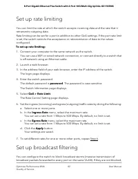
Set up rate limiting You can limit the rate at which the switch accepts incoming data and the rate that itretransmits outgoing data. Rate limiting can be set for a port in addition to other QoS settings. If the port rate limitis set, the switch restricts the acceptance or retransmission of data to t...
Page 44 - Manage Network Settings
5 Manage Network Settings This chapter contains the following sections: • Specify IP address settings for the switch • Use the local browser interface to specify the switch IP address • Manage switch discovery protocols • Manage multicast traffic with IGMP snooping • Set up link aggregation 44
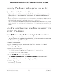
Page 45 - Specify IP address settings for the switch
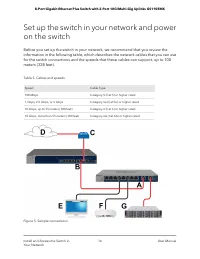
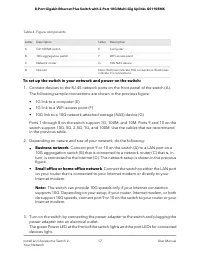
Specify IP address settings for the switch By default, the switch IP address works as follows: • If you cable the switch to a network with a DHCP server before you power on theswitch, the DHCP server assigns an IP address to the switch when the switch ispowered on. • If you power on the switch when ...
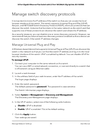
Page 46 - Manage switch discovery protocols; Manage Universal Plug and Play
Manage switch discovery protocols It is important to know the IP address of the switch so that you can access the localbrowser interface of the switch. The switch supports Universal Plug and Play (UPnP),Bonjour, and NETGEAR Switch Discovery Protocol (NSDP), which are protocols that candiscover the s...
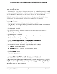
Page 48 - Manage multicast traffic with IGMP snooping
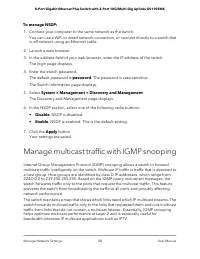
To manage NSDP: 1. Connect your computer to the same network as the switch. You can use a WiFi or wired network connection, or connect directly to a switch thatis off-network using an Ethernet cable. 2. Launch a web browser. 3. In the address field of your web browser, enter the IP address of the sw...
Page 49 - Customize IGMP snooping
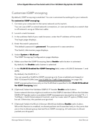
Customize IGMP snooping By default, IGMP snooping is enabled. You can customize the settings for your network. To customize IGMP snooping: 1. Connect your computer to the same network as the switch. You can use a WiFi or wired network connection, or connect directly to a switch thatis off-network us...
Page 50 - Specify a VLAN for IGMP snooping
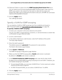
10. (Optional) Select an option from the IGMP Snooping Static Router Port menu. You can select a port to be the dedicated IGMP snooping static router port if noIGMP query exists in the network for the switch to discover the router portdynamically. After a port is selected as the static router port, ...
Page 51 - Set up link aggregation; Set up a static link aggregation group
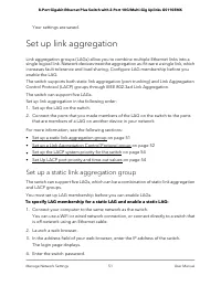
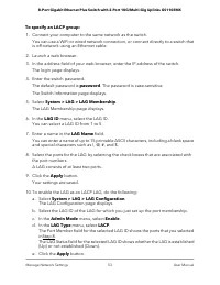
Your settings are saved. Set up link aggregation Link aggregation groups (LAGs) allow you to combine multiple Ethernet links into asingle logical link. Network devices treat the aggregation as if it were a single link, whichincreases fault tolerance and load sharing. Configure LAG membership before ...
Page 52 - Set up a Link Aggregation Control Protocol group
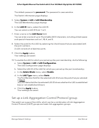
The default password is password. The password is case-sensitive. The Switch Information page displays. 5. Select System > LAG > LAG Membership. The LAG Membership page displays. 6. In the LAG ID menu, select the LAG ID. You can select a LAG ID from 1 to 5. 7. Enter a name in the LAG Name fiel...
Page 54 - Set up the LACP system priority for the switch; Set Up LACP port priority and time-out values
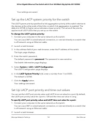
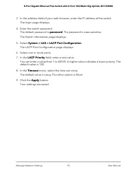
Your settings are saved. Set up the LACP system priority for the switch The LACP system priority specifies the link aggregation priority of the switch relative tothe devices at the other ends of the links on which link aggregation is enabled. Thedefault is 32768. A higher value indicates a lower pri...
Page 56 - Manage and Monitor the Switch
6 Manage and Monitor the Switch This chapter covers the following topics: • Manage flow control • Manage the port speed and the port status • Enable loop prevention • Manage the power saving mode • Manually download and upgrade the firmware • Reboot the switch • Save the switch configuration • Resto...
Page 57 - Manage flow control; Manage the port speed and the port status
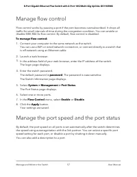
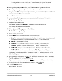
Manage flow control Flow control works by pausing a port if the port becomes oversubscribed. It drops alltraffic for small intervals of time during the congestion condition. You can enable ordisable IEEE 802.3x flow control. By default, flow control is disabled. To manage flow control: 1. Connect yo...
Page 59 - Enable loop prevention; Manage the power saving mode
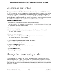
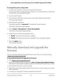
Enable loop prevention If loop prevention is enabled and the switch detects a loop, the switch blocks one ofthe ports that are part of the loop and both LEDs of that port blink at a constant speed.If two ports are part of a loop, the port with the highest port number is blocked. Forexample, if port ...
Page 61 - Reboot the switch
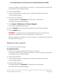
You can use a WiFi or wired network connection, or connect directly to a switch thatis off-network using an Ethernet cable. 6. Launch a web browser. 7. In the address field of your web browser, enter the IP address of the switch. The login page displays. 8. Enter the switch password. The default pas...
Page 62 - Save the switch configuration
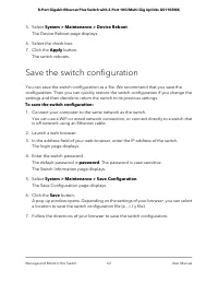
5. Select System > Maintenance > Device Reboot. The Device Reboot page displays. 6. Select the check box. 7. Click the Apply button. The switch reboots. Save the switch configuration You can save the switch configuration as a file. We recommend that you save theconfiguration. Then you can quic...
Page 63 - Restore a saved switch configuration
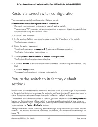
Restore a saved switch configuration You can restore a switch configuration that you saved. To restore the switch configuration that you saved: 1. Connect your computer to the same network as the switch. You can use a WiFi or wired network connection, or connect directly to a switch thatis off-netwo...
Page 65 - Enable port mirroring
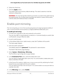
6. Select the check box. 7. Click the Apply button. The switch returns to its factory default settings. The switch restarts to load therestored configuration. WARNING: Do not interrupt the network connection or power to the switch during the reset process. Do not disconnect any Ethernet cables or po...
Page 66 - View or clear the port statistics
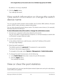
By default, mirroring is disabled. 9. Click the Apply button. Your settings are saved. View switch information or change the switchdevice name You can view the switch product name (model), serial number, MAC address, firmwareversion, DHCP mode, and other network information. You can also change the ...
Page 68 - Diagnostics and Troubleshooting
7 Diagnostics and Troubleshooting This chapter contains the following sections: • Test cable connections • Resolve a subnet conflict to access the switch • Hardware troubleshooting chart 68
Page 69 - Test cable connections; Resolve a subnet conflict to access the switch
Test cable connections You can use the cable diagnostic feature to easily find out the health status of networkcables. If any problems exist, this feature helps quickly locate the point where the cablingfails, allowing connectivity issues to be fixed much faster, potentially saving technicianshours ...
Page 70 - Hardware troubleshooting chart
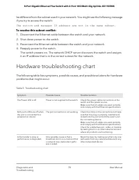
be different from the subnet used in your network. You might see the following messageif you try to access the switch: The switch and manager IP address are not in the same subnet. To resolve this subnet conflict: 1. Disconnect the Ethernet cable between the switch and your network. 2. Shut down pow...
Page 73 - Factory default settings
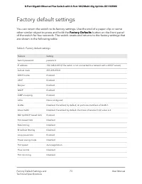
Factory default settings You can return the switch to its factory settings. Use the end of a paper clip or someother similar object to press and hold the Factory Defaults button on the front panelof the switch for four seconds. The switch resets and returns to the factory settings thatare shown in t...
Page 74 - Basic technical specifications
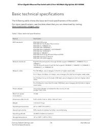
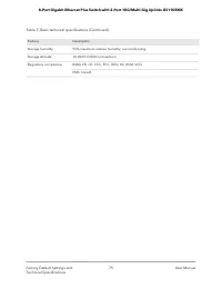
Basic technical specifications The following table shows the basic technical specifications of the switch. For more specifications, see the data sheet that you can download by visitingdownloadcenter.netgear.com. Table 7. Basic technical specifications Description Feature IEEE 802.3 EthernetIEEE 802....
Page 76 - Mount the Switch
B Mount the Switch This appendix includes the following sections: • Attach the switch to a wall • Install the switch in a rack 76
Page 77 - Attach the switch to a wall; Install the switch in a rack
Attach the switch to a wall The switch provides two mount holes on the bottom panel so that you can attach theswitch to a wall. The switch package provides two screws and anchors for that purpose. To attach the switch to a wall: 1. Locate the two mount holes on the bottom panel of the switch. 2. Loc...


 Netgear GS108LP 8xGE PoE
User Manual
Netgear GS108LP 8xGE PoE
User Manual
 Netgear GS116GE 16xGE
User Manual
Netgear GS116GE 16xGE
User Manual
 Netgear GS116LP 16x1GE PoE
User Manual
Netgear GS116LP 16x1GE PoE
User Manual
 Netgear GS305PP 4xGE PoE
User Manual
Netgear GS305PP 4xGE PoE
User Manual
 Netgear GS308PP 8xGE PoE
User Manual
Netgear GS308PP 8xGE PoE
User Manual
 Netgear GS316EP 15x1GE PoE
User Manual
Netgear GS316EP 15x1GE PoE
User Manual
 Netgear GS316PP 16xGE PoE
User Manual
Netgear GS316PP 16xGE PoE
User Manual
 Netgear GS324 24xGE (GS324-200EUS)
User Manual
Netgear GS324 24xGE (GS324-200EUS)
User Manual
 Netgear GS516PP 16xGE PoE
User Manual
Netgear GS516PP 16xGE PoE
User Manual
 Netgear GS524UP 16xGE PoE
User Manual
Netgear GS524UP 16xGE PoE
User Manual
 Netgear GS724T 24xGE, 2xGE SFP
User Manual
Netgear GS724T 24xGE, 2xGE SFP
User Manual
 Netgear S3300-28X (GS728TX) 24x1GE
User Manual
Netgear S3300-28X (GS728TX) 24x1GE
User Manual
 Netgear XS508M 7x100M
User Manual
Netgear XS508M 7x100M
User Manual