Page 2 - Copyright Notice
ii Preface MS-7666 Preface Preface MS-7666 Preface Copyright Notice The material in this document is the intellectual property of MICRO-STAR INTERNA- TIONAL. We take every care in the preparation of this document, but no guarantee is given as to the correctness of its contents. Our products are unde...
Page 3 - Safety Instructions
Preface MS-7666 Preface iii Preface MS-7666 Preface Safety Instructions Always read the safety instructions carefully.Keep this User’s Manual for future reference.Keep this equipment away from humidity.Lay this equipment on a reliable flat surface before setting it up.The openings on the enclosure a...
Page 4 - FCC-B Radio Frequency Interference Statement
iv Preface MS-7666 Preface Preface MS-7666 Preface FCC-B Radio Frequency Interference Statement This equipment has been tested and found to comply with the limits for a Class B digi- tal device, pursuant to Part 15 of the FCC Rules. These limits are designed to provide reasonable protection against ...
Page 5 - Preface; Preface; Preface; WEEE (Waste Electrical and Electronic Equipment) Statement; ENGLISH; эти изделия в специализированные пункты приема.
Preface MS-7666 Preface v Preface MS-7666 Preface WEEE (Waste Electrical and Electronic Equipment) Statement ENGLISH To protect the global environment and as an environmentalist, MSI must remind you that...Under the European Union (“EU”) Directive on Waste Electrical and Elec- tronic Equipment, Dire...
Page 6 - ESPAÑOL; empresa autorizada para la recogida de estos residuos.; NEDERLANDS; lokale inzamelingspunten.; SRPSKI; vode možete vratiti na lokalnim mestima za prikupljanje.; POLSKI
vi Preface MS-7666 Preface Preface MS-7666 Preface ESPAÑOL MSI como empresa comprometida con la protección del medio ambiente, recomienda:Bajo la directiva 2002/96/EC de la Unión Europea en materia de desechos y/o equi- pos electrónicos, con fecha de rigor desde el 13 de agosto de 2005, los producto...
Page 7 - vii; TÜRKÇE; noktalarına bırakabilirsiniz.; ČESKY
Preface MS-7666 Preface vii Preface MS-7666 Preface TÜRKÇE Çevreci özelliğiyle bilinen MSI dünyada çevreyi korumak için hatırlatır:Avrupa Birliği (AB) Kararnamesi Elektrik ve Elektronik Malzeme Atığı, 2002/96/EC Kararnamesi altında 13 Ağustos 2005 tarihinden itibaren geçerli olmak üzere, elektrikli ...
Page 8 - Contents
viii Preface MS-7666 Preface Preface MS-7666 Preface Contents Copyright Notice ............................................................................................ iiTrademarks .................................................................................................... iiRevision His...
Page 9 - ix
Preface MS-7666 Preface ix Preface MS-7666 Preface Français ..................................................................................................... Fr-1 Spécifications ......................................................................................................Fr-2Guide Rapide...
Page 11 - English; XPower Series; Europe version
Page 12 - Mainboard Specifications
En-2 MS-7666 Mainboard Mainboard Specifications Processor Support Intel ® Bloomfield TM processor in the LGA1366 package (For the latest information about CPU, please visit http://www.msi.com/index. php?func=cpuform2) QPI Up to 6.4 GT/s Chipset North Bridge : Intel ® X58 chipset South Bridge : Intel...
Page 13 - Connectors
En-3 English Connectors Back panel 1 PS/2 keyboard port 1 PS/2 mouse port 1 Clear CMOS button 1 D-LED2 panel connector 1 1394 port 5 USB 2.0 ports 1 ESATA port 1 ESATA/ USB 2.0 Combo port 2 LAN ports 2 USB 3.0 ports On-Board 2 USB 2.0 connectors 1 1394 connector 1 Chassis Intrusion connector 1 TPM M...
Page 14 - Quick Components Guide
En-4 MS-7666 Mainboard OC Genie Quick Components Guide Back Panel, En-14 CPU, En-5 CPUFAN, En-17 DDR3, En-9 Reset Button, En-21 JPWR2, En-12 JPWR1, En-12 SYSFAN2, En-17 SATA, En-16 JFP1, JFP2, En-19 JUSB1~2, En-18 Base Clock Control Buttons, En-22 OC Genie Button, En-22 J1394_1, En-19 JPWR4, En-13 J...
Page 15 - Important; Overheating; Introduction to LGA 1366 CPU; ber to apply some thermal paste on it for; Alignment Key
En-5 English CPU (Central Processing Unit) When you are installing the CPU, make sure to install the cooler to prevent overheating. If you do not have the CPU cooler, consult your dealer before turning on the computer. For the latest information about CPU, please visit http://www.msi.com/index. php?...
Page 16 - CPU & Cooler Installation
En-6 MS-7666 Mainboard CPU & Cooler Installation When you are installing the CPU, make sure the CPU has a cooler attached on the top to prevent overheating. Meanwhile, do not forget to apply some thermal paste on CPU before installing the heat sink/cooler fan for better heat dispersion. Follow t...
Page 19 - compatible components, please visit; Memory Population Rule; Single-Channel mode Population Rule
En-9 English Memory These DIMM slots are used for installing memory modules. For more information on compatible components, please visit http://www.msi.com/index.php?func=testreport DDR3 240-pin, 1.5V 48x2=96 pin 72x2=144 pin Memory Population Rule Please refer to the following illustrations for mem...
Page 20 - of the same type and density in different channel DIMM slots.
En-10 MS-7666 Mainboard Triple-Channel mode Population Rule In Triple-Channel mode, the memory modules can transmit and receive data with three data bus lines simultaneously. Enabling Triple-Channel mode can enhance the best system performance. When you have three or more memory modules, please alwa...
Page 21 - Installing Memory Modules
En-11 English To enable successful system boot-up, always insert the memory modules into the DIMM_1 (DIMM_A0 in v1.0 PCB) first.Due to the chipset resource deployment, the system density will only be detected up to 23+GB (not full 24GB) when each DIMM is installed with a 4GB memory module. Installin...
Page 22 - Power Supply; These connectors provide 12V power output to the CPUs.
En-12 MS-7666 Mainboard Power Supply ATX 24-pin Power Connector: JPWR1 This connector allows you to connect an ATX 24-pin power supply. To connect the ATX 24-pin power supply, make sure the plug of the power supply is inserted in the proper orientation and the pins are aligned. Then push down the po...
Page 23 - This connector is used to provide power to the graphics card.
En-13 English ATX 6-pin Power Connector: JPWR4 This connector is used to provide power to the graphics card. Important Make sure that all the connectors are connected to proper ATX power supplies to ensure stable operation of the mainboard.Power supply of 450 watts (and above) is highly recommended ...
Page 24 - Back Panel; mouse/keyboard DIN connector is for a PS/2; D-LED2 Panel Connector
En-14 MS-7666 Mainboard Back Panel Mouse/Keyboard The standard PS/2 ® mouse/keyboard DIN connector is for a PS/2 ® mouse/keyboard. Clear CMOS Button There is a CMOS RAM on board that has a power supply from external battery to keep the system configuration data. With the CMOS RAM, the system can aut...
Page 25 - ESATA Port; LAN
En-15 English ESATA Port The ESATA (External SATA) port is for attaching the ESATA hard drive. ESATA/ USB 2.0 Combo Port The ESATA/USB 2.0 combo port is for attaching the ESATA external hard drive or USB device. USB 3.0 Port USB 3.0 port is backward-compatible with USB 2.0 devices. Supports data tra...
Page 26 - to one Serial ATA device.; supported by Intel; occur during transmission.
En-16 MS-7666 Mainboard Connectors Serial ATA Connector: SATA1~8 This connector is a high-speed Serial ATA interface port. Each connector can connect to one Serial ATA device. * The MB layout in this figure is for reference only. SATA5_6 SATA3_4 SATA1_2 SATA1~6 (3Gb/s) supported by Intel ® ICH10R SA...
Page 27 - CPUFAN
En-17 English Fan Power Connectors: CPUFAN,SYSFAN1~4 The fan power connectors support system cooling fan with +12V. When connecting the wire to the connectors, always note that the red wire is the positive and should be con- nected to the +12V; the black wire is Ground and should be connected to GND...
Page 28 - This connector, compliant with Intel; BIOS utility and clear the record.
En-18 MS-7666 Mainboard Front USB Connector: JUSB1 / JUSB2 This connector, compliant with Intel ® I/O Connectivity Design Guide, is ideal for con- necting high-speed USB interface peripherals such as USB HDD, digital cameras, MP3 players, printers, modems and the like. * The MB layout in this figure...
Page 29 - The JFP1 is compliant with Intel
En-19 English IEEE1394 Connector: J1394_1 This connector allows you to connect the IEEE1394 device via an optional IEEE1394 bracket. * The MB layout in this figure is for reference only. 1394 Bracket (optional) Front Panel Connectors: JFP1, JFP2 These connectors are for electrical connection to the ...
Page 30 - TPM Module connector: JTPM1
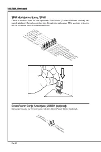
En-20 MS-7666 Mainboard TPM Module connector: JTPM1 This connector connects to a TPM (Trusted Platform Module) module (optional). Please refer to the TPM security platform manual for more details and usages. 10.N o Pin 14.G roun d 8.5V Pow er 12.G roun d 6.Se rial IR Q 4.3.3 V Po wer 2.3V Stan dby p...
Page 31 - Power Button
En-21 English Button The mainboard provides the following buttons for you to set the computer’s function. This section will explain how to change your mainboard’s function through the use of button. Power Button This button is used to turn-on or turn-off the system. Press the button to turn-on or tu...
Page 32 - OC Genie Button; and the system will restore the default for next boot.; when the system is in regular operation state.
En-22 MS-7666 Mainboard OC Genie Button This button is used to auto-overclock for the system. Press this button to enable the OC Genie function when the system is in power off state, meanwhile, the button will light and lock. And then the system will automatically detect the optimum values to overcl...
Page 35 - PCIE (Peripheral Component Interconnect Express) Slot; PCI Express x16 Slot; switches or BIOS configuration.; PCIE x16 slots Population Rule
En-25 English Slots PCIE (Peripheral Component Interconnect Express) Slot The PCI Express slot supports the PCI Express interface expansion card. PCI Express x16 Slot PCI Express x1 Slot Important When adding or removing expansion cards, make sure that you unplug the power sup- ply first. Meanwhile,...
Page 37 - The way for installing four expansion card:
En-27 English The way for installing four expansion card: PCI_E2 PCI_E3 PCI_E4 PCI_E5 PCI_E6 PCI_E7 The way for installing five expansion card: PCI_E2 PCI_E3 PCI_E4 PCI_E5 PCI_E6 PCI_E7 The way for installing six expansion card: PCI_E2 PCI_E3 PCI_E4 PCI_E5 PCI_E6 PCI_E7 ■ ■ ■ Installed Empty
Page 38 - ATI CrossFireX
En-28 MS-7666 Mainboard ATI CrossFireX TM (Multi-GPU) Technology ATI CrossFireX TM is the ultimate multi-GPU performance gaming platform. Enabling game-dominating power, ATI CrossFireX TM technology enables two or more discrete graphics processors to work together to improve system performance. ATI ...
Page 40 - NVIDIA
En-30 MS-7666 Mainboard NVIDIA ® SLI Technology NVIDIA ® SLI (Scalable Link Interface) technology allows two GPUs to run in tandem within a system to achieve up to twice the performance of a single graphics card. To utilize this technology, the two GPU cards must be connected by an SLI Video Link ca...
Page 41 - tiGPU” function is disabled.
En-31 English Check the box Important If you want to remove one graphics card and quit the SLI function, make sure the “Mul- tiGPU” function is disabled. After the hardware installation is completed, restart the system and install the NV SLI driver/utility. A configuration panel will be provided for...
Page 43 - CPU Phase LEDs; QPI Phase LEDs; Lights
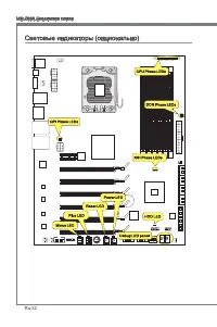
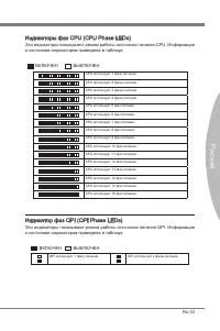
En-33 English CPU Phase LEDs These LEDs indicate the current CPU power phase mode. Follow the instructions below to read. Lights Off CPU is in 1 phase power mode. CPU is in 2 phase power mode. CPU is in 3 phase power mode. CPU is in 4 phase power mode. CPU is in 5 phase power mode. CPU is in 6 phase...
Page 44 - Lights when the hard drive is operating.
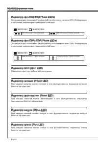
En-34 MS-7666 Mainboard IOH Phase LEDs These LEDs indicate the current IOH power phase mode. Follow the instructions below to read. Lights Off IOH is in 1 phase power mode. IOH is in 2 phase power mode. DDR Phase LEDs These LEDs indicate the current DDR power phase mode. Follow the instructions belo...
Page 45 - Debug LED Panel
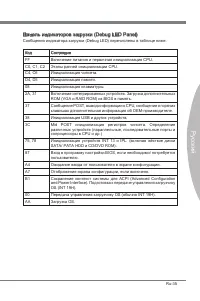
En-35 English Debug LED Panel Please refer to the table below to get more information about the Debug LED mes- sage. Post Status FF Power on and first initialize CPU. C0, C1, C2 Early CPU Initialize. C4, C6 Initialize chipset. D4, D5 Initialize memory. 08 Initialize keyboard. 2A, 31 Initialize onboa...
Page 46 - BIOS Setup
En-36 MS-7666 Mainboard BIOS Setup This chapter provides basic information on the BIOS Setup program and allows you to configure the system for optimum use. You may need to run the Setup program when: An error message appears on the screen during the system booting up, and requests you to run BIOS S...
Page 47 - Entering Setup; Main Menu
En-37 English Entering Setup Power on the computer and the system will start POST (Power On Self Test) process. When the message below appears on the screen, press <DEL> key to enter Setup. Press DEL to enter SETUP If the message disappears before you respond and you still wish to enter Setup,...
Page 51 - Change these settings only if you are familiar with the chipset.
En-41 English Cell Menu Introduction : This menu is for advanced user who want to overclock the mainboard. 4. Important Change these settings only if you are familiar with the chipset. Current CPU / DRAM / QPI Frequency These items show the current frequencies of CPU, Memory and QPI. Read-only. CPU ...
Page 57 - Failed Overclocking Resolution
En-47 English Important Failed Overclocking Resolution This mainboard supports overclocking greatly. However, please make sure your pe- ripherals and components are bearable for some special settings. Any operation that exceeds product specification is not recommended. Any risk or damge resulting fr...
Page 58 - Software Information; your desire and to activate the device.
En-48 MS-7666 Mainboard Software Information Take out the Driver/Utility DVD that is included in the mainboard package, and place it into the DVD-ROM drive. The installation will auto-run, simply click the driver or utility and follow the pop-up screen to complete the installation. The Driver/Utilit...
Page 59 - Deutsch; XPower Serie
Page 60 - Spezifikationen
De-2 MS-7666 Mainboard Spezifikationen Prozessoren Intel ® Bloomfield TM Prozessoren für Sockel LGA1366 (Weitere CPU Informationen finden Sie unter http://www.msi.com/index. php?func=cpuform2) QPI Bis zu 6,4 GT/s Chipsatz North-Bridge : Intel ® X58 Chipsatz South-Bridge : Intel ® ICH10R Chipsatz Spe...
Page 61 - Anschlüsse
De-3 Deutsch Anschlüsse Hintere Ein-/ und Ausgänge 1 PS/2 Mausanschluss 1 PS/2 Tastaturanschlus 1 CMOS leeren-Taste 1 D-LED2 Paneelverbinder 1 1394 Anschluss 5 USB 2.0 Anschlüsse 1 ESATA Anschluss 1 ESATA/ USB 2.0 Combo Anschluss 2 LAN Anschlüsse 2 USB 3.0 Anschlüsse On-Board 2 USB 2.0 Stiftleisten ...
Page 62 - Komponenten-Übersicht
De-4 MS-7666 Mainboard OC Genie Komponenten-Übersicht R ü c k t a f e l , De-14 CPU, De-5 CPUFAN, De-17 DDR3, De-9 Reset-Taste, De-21 JPWR2, De-12 JPWR1, De-12 SYSFAN2, De-17 SATA, De-16 JFP1, JFP2, De-19 JUSB1~2, De-18 Haupt-Taktsteuerung Tasten, De-22 OC Genie Taste, De-22 J1394_1, De-19 JPWR4, De...
Page 63 - Wichtig
De-5 Deutsch CPU (Prozessor) Wenn Sie die CPU einbauen, stellen Sie bitte sicher, dass Sie auf der CPU einen Kühler anbringen, um Überhitzung zu vermeiden. Verfügen Sie über keinen Kühler, setzen Sie sich bitte mit Ihrem Händler in Verbindung, um einen solchen zu erwerben und zu installieren. Um die...
Page 64 - Justiermarkierungen
De-6 MS-7666 Mainboard CPU & Kühler Einbau Wenn Sie die CPU einbauen, stellen Sie bitte sicher, dass Sie auf der CPU einen Kühler anbringen, um Überhitzung zu vermeiden. Vergessen Sie nicht, etwas Siliziumwärmel- eitpaste auf die CPU aufzutragen, bevor Sie den Prozessorkühler installieren, um ei...
Page 67 - mationen über kompatible Bauteile finden Sie unter; Hinweise für den Einsatz von Speichermodulen; Populationsregeln für Einkanal-Modus
De-9 Deutsch Speicher Diese DIMM-Steckplätze nehmen Arbeitsspeichermodule auf. Die neusten Infor- mationen über kompatible Bauteile finden Sie unter http://www.msi.com/index. php?func=testreport DDR3 240-polig, 1,5V 48x2=96 Pole 72x2=144 Pole Hinweise für den Einsatz von Speichermodulen Bitte beacht...
Page 68 - legen Sie sie immer, wie die Zahlen in unten gezeigt.
De-10 MS-7666 Mainboard Populationsregeln für Drei-Kanal-Modus Im Drei-Kanal-Modus können Arbeitsspeichermodule Daten über drei Datenbusleitun- gen gleichzeitig senden und empfangen. Durch Aktivierung des Drei-Kanal-Modus wird die Leistung Ihres Systems verbessert. Wenn Sie drei oder mehr Speichermo...
Page 69 - Vorgehensweise beim Einbau von Speicher Modulen
De-11 Deutsch Um einen sicheren Systemstart, zu gewährleisten, bestücken Sie immer DIMM_1 (DIMM_A0 in PCB v1.0) zuerst.Aufgrund der Chipsatzressourcennutzung wird nur eine Systemdichte bis 23+GB (not full 24GB) erkannt, wenn jeder DIMM Slot mit einem 4GB Speichermodul be- setzt wird. Vorgehensweise ...
Page 70 - Stromversorgung; Verbindung zu gewährleisten.
De-12 MS-7666 Mainboard Stromversorgung ATX 24-poliger Stromanschluss: JPWR1 Mit diesem Anschluss verbinden Sie den ATX 24-poligen Anschluss des Netzteils. Achten Sie bei dem Verbinden des ATX 24-poligen Stromanschlusses darauf, dass der Anschluss des Netzteils richtig auf den Anschluss an der Haupt...
Page 72 - Rücktafel; Maus/Tastatur Stecker Mini DIN ist für eine PS/2; in den Werkszustand zurücksetzen
De-14 MS-7666 Mainboard Rücktafel Maus/Tastatur Die Standard PS/2 ® Maus/Tastatur Stecker Mini DIN ist für eine PS/2 ® Maus/Tastatur. CMOS leeren-Taste Der Onboard CMOS Speicher (BIOS), enthält Grundinformationen sowie erweite Eistellungen des Mainboards. Der CMOS Speicher wird über eine Betterie mi...
Page 74 - Anschlüssen
De-16 MS-7666 Mainboard Anschlüssen Serial ATA Anschluss: SATA1~8 Der Anschluss ist eine Hochgeschwindigkeitsschnittstelle der Serial ATA. Pro An- schluss kann ein S-ATA Geräte angeschlossen werden. * Das MB-Layout in dieser Abbildung haben nur Orientierungscharakter. SATA5_6 SATA3_4 SATA1_2 SATA1~6...
Page 75 - die Vorteile der Steuerung des CPU Lüfters zu nutzen.; von der CPUFAN Temperaturen steuert.
De-17 Deutsch Stromanschlüsse für Lüfter: CPUFAN,SYSFAN1~4 Die Anschlüsse unterstützen aktive Systemlüfter mit + 12V. Wenn Sie den Anschluss herstellen, sollten Sie immer darauf achten, dass der rote Draht der positive Pol ist, und mit +12V verbunden werden sollte. Der schwarze Draht ist der Erdkont...
Page 76 - Dieser Anschluss entspricht den Richtlinien des Intel; gerufen und die Aufzeichnung gelöscht werden.
De-18 MS-7666 Mainboard USB Vorderanschluss: JUSB1 / JUSB2 Dieser Anschluss entspricht den Richtlinien des Intel ® I/O Connectivity Design Guide. Er ist bestens geeignet, Hochgeschwindigkeits- USB- Peripheriegeräte anzuschließen, wie z.B. USB Festplattenlaufwerke, Digitalkameras, MP3-Player, Drucker...
Page 77 - schluss eines IEEE 1394-Gerätes ermöglicht.
De-19 Deutsch IEEE1394 Anschluss: J1394_1 Mit diesem Anschluss verbinden Sie ein optionales IEEE 1394-Modul, das den An- schluss eines IEEE 1394-Gerätes ermöglicht. * Das MB-Layout in dieser Abbildung haben nur Orientierungscharakter. 1394 Slotblech (optional) Frontpanel Anschlüsse: JFP1, JFP2 Diese...
Page 78 - TPM Modul Anschluss: JTPM1; en Sie bitte dem TPM Plattform Handbuch.
De-20 MS-7666 Mainboard TPM Modul Anschluss: JTPM1 Dieser Anschluss wird für das optionale TPM Modul (Trusted Platform Module) ver- wendt. Weitere Informationen über den Einsatz des optionalen TPM Modules entnehm- en Sie bitte dem TPM Plattform Handbuch. 10.N o Pin 14.G roun d 8.5V Pow er 12.G roun ...
Page 79 - durch den Gebrauch der Taste ändert.
De-21 Deutsch Tasten Das Motherboard unterstützt die folgende Tasten, um die Funktion des Computers einzustellen. Dieser Abschnitt beschreibt, wie man die Funktionen des Motherboards durch den Gebrauch der Taste ändert. Ein-/Ausschalter Dieser Ein-/ Ausschalter verwendet, um das System ein- und ausz...
Page 80 - OC Genie Taste; wiederher
De-22 MS-7666 Mainboard OC Genie Taste Diese Taste wird zum Selbstübertaktung für das System benutzt. Drücken Sie diese Taste, um der OC Genie Funktion zu ermöglichen, wenn das System im spannung- slosen Zustand ist, unterdessen die Taste beleuchtet und sich verriegelt. Nach dem Boot des Systems und...
Page 81 - Überspannungschalter
De-23 Deutsch Schalter Das Motherboard unterstützt den folgende Schalter, um die Funktion des Computers einzustellen. Dieser Abschnitt beschreibt, wie man die Funktionen des Motherboards durch den Gebrauch des Schalters ändert. Überspannungschalter Sie können das CPU/ QPI/ Speichers (DDR)/ IOH verst...
Page 83 - PCIE (Peripheral Component Interconnect Express) Steckplatz; PCI Express x16 Steckplatz
De-25 Deutsch Steckplätze PCIE (Peripheral Component Interconnect Express) Steckplatz Der PCI Express-Steckplatz unterstützt eine Erweiterungskarte mit der PCI Express-Schnittstelle. PCI Express x16 Steckplatz PCI Express x1 Steckplatz Wichtig Achten Sie darauf, dass Sie zuerst das Netzkabel aus der...
Page 85 - Die Methode für die Installation von vier Erweiterungskarten:
De-27 Deutsch Die Methode für die Installation von vier Erweiterungskarten: PCI_E2 PCI_E3 PCI_E4 PCI_E5 PCI_E6 PCI_E7 Die Methode für die Installation von fünf Erweiterungskarten: PCI_E2 PCI_E3 PCI_E4 PCI_E5 PCI_E6 PCI_E7 Die Methode für die Installation von sechs Erweiterungskarten: PCI_E2 PCI_E3 P...
Page 87 - Ein CrossFireX; System hat vier mögliche Modi des Displays:
De-29 Deutsch Wählen Sie erweiterte Ansicht vom Ansich- taufklappmenü aus. Wichtig Ein CrossFireX TM System hat vier mögliche Modi des Displays: SuperTilingScissor ModeAlternate Frame RenderingSuper Anti-aliasing. Weitere Informationen befrangen Sie das Benutzerhandbuch der Grafikkarte vom Her- stel...
Page 88 - Die NVIDIA; Graphikkarte sicherzustellen.
De-30 MS-7666 Mainboard NVIDIA ® SLI Technologie Die NVIDIA ® SLI (Scalable Link Interface) Technologie gestattet es zwei GPUs im Tan- dembetrieb innerhalb eines Systems zu betreiben, so dass diese bis hin zur doppelten Leistung einer einzelnen Grafikkarte erreichen. Um diese Technologieeinsetzen zu...
Page 89 - kehren, stellen Sie sicher, dass die “MultiGPU” Funktion abschalten.
De-31 Deutsch Wählen Sie denKasten aus Wichtig Wollen Sie eine Grafikkarte entfernen und vom SLI-Modus zum Normalbetrieb zurück- kehren, stellen Sie sicher, dass die “MultiGPU” Funktion abschalten. Beenden Sie die Hardwareeinrichtung, führen Sie einen Neustart durch undinstal- lieren Sie den NV SLI ...
Page 91 - Leuchtet
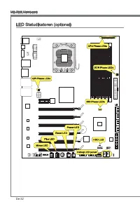
De-33 Deutsch CPU Phase LEDs Diese LEDs zeigen den gegenwärtigen CPU Power-Modus an. Lesen Sie die folgenden Anweisungen. Leuchtet Aus CPU befindet sich in der Phase 1 des Power-Modus. CPU befindet sich in der Phase 2 des Power-Modus. CPU befindet sich in der Phase 3 des Power-Modus. CPU befindet si...
Page 92 - IOH Phase LEDs; DDR Phase LEDs; HDD LED
De-34 MS-7666 Mainboard IOH Phase LEDs Diese LEDs zeigen den gegenwärtigen IOH Power-Modus an. Lesen Sie die folgenden Anweisungen. Leuchtet Aus IOH befindet sich in der Phase 1 des Power-Modus. IOH befindet sich in der Phase 2 des Power-Modus. DDR Phase LEDs Diese LEDs zeigen den gegenwärtigen DDR ...
Page 94 - Sie zum Aufruf des BIOS SETUP aufgefordert werden.; te - 5te Stelle bezeichnen die Modelnummer.
De-36 MS-7666 Mainboard BIOS Setup Dieses Kapitel enthält Informationen über das BIOS Setup und ermöglicht es Ihnen, Ihr System optimal auf Ihre Anforderungen einzustellen. Notwendigkeit zum Aufruf des BIOS besteht, wenn: Während des Bootvorgangs des Systems eine Fehlermeldung erscheint und Sie zum ...
Page 95 - Aufruf des BIOS Setups; Nach dem Start des Setup Menüs erscheint zuerst das Hauptmenü.
De-37 Deutsch Aufruf des BIOS Setups Nach dem Einschalten beginnt der Computer den POST (Power On Self Test -Selb- stüberprüfung nach Anschalten). Sobald die Meldung unten erscheint, drücken Sie die Taste <Entf>(<Del>) um das Setup aufzurufen. Press DEL to enter SETUP (ENTF drücken, um d...
Page 98 - auf der MSI Website ein.
De-40 MS-7666 Mainboard Wenn Sie das BIOS Dienstprogramm öffnen, folgen Sie den untenstehenden An- weisungen. Laden der optimalen Voreinstellung : Verwenden Sie die Steuerschlüssel (↑↓), um dem Laden der optimalen Voreinstellung zu wählen und drücken Sie auf <Eing- abe>. Dann erscheint die fol...
Page 105 - Auflösung für verfehlte Übertaktung
De-47 Deutsch Wichtig Auflösung für verfehlte Übertaktung Die Hauptplatine unterstützt die meisten Ubertaktungen. Aber stellen Sie sicher, dass Ihre Peripherie und Komponenten füt einige spezielle Einstellungen erträglich sind. Die Operation, welche die Produktspezifikation übersteigen, wird nicht e...
Page 106 - Mainboard Unterstützungen.; System Leistung zu erhalten.
De-48 MS-7666 Mainboard Software-Information Die im Mainboard-Paket enthaltene DVD enthält alle notwendigen Treiber. Um die Installation automatisch laufen zu lassen, klicken Sie einfach den Treiber oder Utiltiy und folgen Sie dem Pop-Up Schirm, um die Installation durchzuführen. Der Treiberge- brau...
Page 107 - Français; XPower Séries
Page 108 - Spécifications
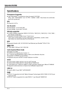
Fr-2 Carte mère MS-7666 Spécifications Processeurs Supportés Intel ® Bloomfield TM processeurs dans le paquet LGA1366 (Pour plus d'information sur le CPU, veuillez visiter http://www.msi.com/index. php?func=cpuform2) QPI Jusqu’à 6.4 GT/s Jeu de puces North Bridge : puce Intel ® X58 South Bridge : pu...
Page 109 - Connecteurs
Fr-3 Français Connecteurs Panneau arrière 1 port clavier PS/2 1 port souris PS/2 1 bouton d’effacement CMOS 1 connecteur de panneau D-LED2 1 port 1394 5 ports USB 2.0 1 port ESATA 1 port ESATA/ USB 2.0 Combo 2 ports LAN 2 ports USB 3.0 Connecteurs intégrés 2 connecteurs USB 2.0 1 connecteur 1394 1 c...
Page 110 - Guide Rapide Des Composants
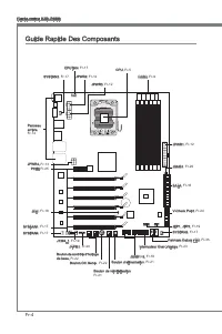
Fr-4 Carte mère MS-7666 OC Genie Guide Rapide Des Composants Panneau arrière, Fr-14 CPU, Fr-5 CPUFAN, Fr-17 DDR3, Fr-9 Bouton de réinitialisation, Fr-21 JPWR2, Fr-12 JPWR1, Fr-12 SYSFAN2, Fr-17 SATA, Fr-16 JFP1, JFP2, Fr-19 JUSB1~2, Fr-18 Bouton de contrôle d'horloge de base, Fr-22 Bouton OC Genie ,...
Page 111 - Clé d’aligement
Fr-5 Français Processeur : CPU Quand vous installez le CPU, veuillez vous assurer d’installer un ventilateur pour éviter la surchauffe. Si vous n’en avez pas, contactez votre revendeu pour en acheter et in- stallez-les avant d’allumer votre ordinateur. Pour plus d’informations sur le CPU, veuillez v...
Page 112 - Installation du CPU et son ventilateur; Clé d’alignement
Fr-6 Carte mère MS-7666 Installation du CPU et son ventilateur Quand vous installez le CPU, assurez-vous que le CPU soit équipé d’un ventilateur de refroidissement attaché sur le dessus pour éviter la surchauffe. Méanmoins, n’oubliez pas d’appliquer une couche d’enduit thermique sur le CPU avant d’i...
Page 115 - Règles de population de la mémoire; un
Fr-9 Français Mémoire Ces slots DIMM sont destinés à installer les modules de mémoire. Pour plus d’informations sur les composants compatibles, veuillez visiter http://www.msi.com/in- dex.php?func=testreport DDR3 240-pin, 1.5V 48x2=96 pin 72x2=144 pin Règles de population de la mémoire Veuillez vous...
Page 116 - Règle de population du mode triple-canaux; trois; ou; plus; mémoire du; même type; et de la; même densité; dans les slots DIMM de canaux
Fr-10 Carte mère MS-7666 Règle de population du mode triple-canaux En mode trois-canaux, les modules de mémoire peuvent transmettre et recevoir les données avec trois lignes bus de données sémultanément. L’activation du mode trois- canaux peut l’augmenter à la meuilleure performance du système. Quan...
Page 117 - de mémoire dans; Installation des modules de mémoire; du slot DIMM sur les côtés.; inséré dans le slot du DIMM.
Fr-11 Français Pour lancer avec succès votre ordinateur, insérez toujours tout d’abord les modules de mémoire dans DIMM_1 (DIMM_A0 dans PCB v1.0) d’a bor d . A cause du développement de la ressource du chipset, la densité du système sera détecté seulement jusqu’à 23+GB (non 24GB) quand chaque DIMM e...
Page 118 - Connecteurs d’alimentation; Connecteur d’alimentation ATX 24-pin : JPWR1
Fr-12 Carte mère MS-7666 Connecteurs d’alimentation Connecteur d’alimentation ATX 24-pin : JPWR1 Ce connecteur vous permet de connecter l’alimentation ATX 24-pin. Pour cela, as- surez-vous que la prise d’alimentation est bien positionnée dans le bon sens et que les goupilles soient alignées. Enfonce...
Page 119 - Connecteur d’alimentation ATX 6-pin : JPWR4
Fr-13 Français Connecteur d’alimentation ATX 6-pin : JPWR4 Ce connecteur d’alimentation sert à fournir de l’alimentation à la carte graphics. Important Veuillez vous assurer que tous les connecteurs sont connectés aux correctes alimen- tations ATX pour garantir une opération stable de la carte mère....
Page 120 - Panneau arrière
Fr-14 Carte mère MS-7666 Panneau arrière Souris/Clavier Le standard connecteur de souris/clavier DIN de PS/2 ® est pour une souris ou un clavier de PS/2 ® . Bouton d’effacement CMOS Il y a un CMOS RAM intégré, qui possède un bloc d’alimentation alimenté par une bat- terie externe, destiné à conserve...
Page 121 - Port ESATA
Fr-15 Français Port ESATA Le port ESATA (External-SATA) sert à attacher un disque dur E-SATA. Port ESATA/ USB 2.0 Combo Le port ESATA/USB 2.0 combo sert à attacher le lecteur dur externe ESATA ou un périphérique USB. Port USB 3.0 Le port USB 3.0 est inférieur-compatible avec les périphériques USB 2....
Page 122 - être relié à un appareil de série ATA.; supportés par Intel; pourraient se produire pendant la transmission
Fr-16 Carte mère MS-7666 Connecteurs Connecteur Sérial ATA : SATA1~8 Ce connecteur est un port d’interface de série ATA haut débit. Chaque connecteur peut être relié à un appareil de série ATA. *Le schéma de carte mère dans la figure n’est qu’à titre de référence. SATA5_6 SATA3_4 SATA1_2 SATA1~6 (3G...
Page 123 - afin de contrôler le ventilateur de l’unité centrale.
Fr-17 Français Connecteur d’alimentation du ventilateur : CPUFAN,SYSFAN1~4 Les connecteurs de courant du ventilateur supportent le ventilateur de refroidissement du système avec +12V. Lors du branchement des fils aux connecteurs, faites toujours en sorte que le fil rouge soit le fil positif devant ê...
Page 124 - chées correctement afin d’éviter tout dommage possible.; Connecteur Châssis Intrusion : JCI1
Fr-18 Carte mère MS-7666 Connecteur USB avant : JUSB1 / JUSB2 Ce connecteur est conforme au guide de conception de la connectivité Entrée/sortie du panneau avant Intel ® , il est idéal pour relier les périphériques d’interface USB à haut débit tels les disques durs externes, les appareils photo numé...
Page 125 - trée/sortie du panneau avant Intel
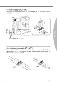
Fr-19 Français Connecteur IEEE1394 : J1394_1 Ce connecteur vous permet de relier un appareil IEEE1394 via un support en option IEEE1394. * Le schéma de carte mère dans la figure n’est qu’à titre de référence. Support IEEE1394 (en option) Connecteur panneau avant : JFP1, JFP2 Ce connecteur est fourni...
Page 126 - Connecteur du Module TPM : JTPM1
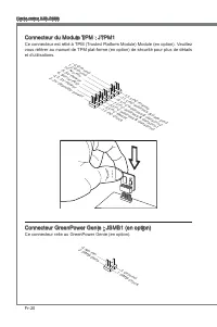
Fr-20 Carte mère MS-7666 Connecteur du Module TPM : JTPM1 Ce connecteur est rélié à TPM (Trusted Platform Module) Module (en option). Veuillez vous référer au manuel de TPM plat-forme (en option) de sécurité pour plus de détails et d’utilisations. 10.N o Pin 14.G roun d 8.5V Pow er 12.G roun d 6.Se ...
Page 127 - mère avec ces boutons.; Bouton d’alimentation; pour allumer ou éteindre le système; Bouton de réinitialisation
Fr-21 Français Bouton La carte mère possède des boutons ci-dessous pour vous de régler la fonction de l’ordinateur. Cette section vous explique comment changer la fonction de votre carte mère avec ces boutons. Bouton d’alimentation Ce bouton d’alimentation sert à allumer ou éteindre le système. Appu...
Page 128 - Bouton OC Genie; prochaine initialisation
Fr-22 Carte mère MS-7666 Bouton OC Genie Ce bouton sert à auto-overclocker pour le système. Appuyez sur ce bouton pour activer la fonction OC Genie lorsque le système est au statut éteint, néanmoins, le bouton s’allume et se verrouille. En suite, le système détectera automatiquement les valeurs opti...
Page 129 - Interrupteur Over-Voltage
Fr-23 Français Interrupteur Cette carte mère vous fournit les interrupteurs suivants pour régler la fonction d’ordinateur. Cette partie vous explique comment changer la fonction de la carte mère au travers l’utilisation d’interrupteurs. Interrupteur Over-Voltage Cet interrupteur sert à élargir la ga...
Page 130 - Point de vérification du voltage : V-Check Point
Fr-24 Carte mère MS-7666 Point de vérification du voltage : V-Check Point Cet équipement de point de vérification du voltage sert à mesurer le voltage actuel du CPU/ QPI/ DDR/ IOH/ ICH. CPU QPI DDR IOH ICH GND CPU GND Voltage CPU : mesurer le voltage actuel du CPU avec le point CPU et le point GND à...
Page 131 - Emplacement PCIE (Peripheral Component Interconnect Express); Emplacement PCI Express x16; configuration du BIOS.; Règle de population d’emplacement PCIE x16
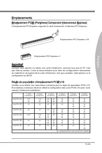
Fr-25 Français Emplacements Emplacement PCIE (Peripheral Component Interconnect Express) L’emplacement PCI Express supporte la carte d’extension d’Interface PCI Express. Emplacement PCI Express x16 Emplacment PCI Express x1 Important Lorsque vous ajoutez ou retirez une carte d’extension, assurez-vou...
Page 133 - La façon d’installer quatre cartes d’extention :
Fr-27 Français La façon d’installer quatre cartes d’extention : PCI_E2 PCI_E3 PCI_E4 PCI_E5 PCI_E6 PCI_E7 La façon d’installer cinq cartes d’extention : PCI_E2 PCI_E3 PCI_E4 PCI_E5 PCI_E6 PCI_E7 La façon d’installer six cartes d’extention : PCI_E2 PCI_E3 PCI_E4 PCI_E5 PCI_E6 PCI_E7 ■ ■ ■ Installé Vi...
Page 137 - la fonction “MultiGPU” est désactivée.
Fr-31 Français Vérifier la boîte Important Si vous voulez enlever une carte graphique et quitter la fonction SLI, assurez-vous que la fonction “MultiGPU” est désactivée. Après l’installation du matériel, redémarrez le système et installez le pilote/unité NV SLI. Un panneau de configuration est fourn...
Page 139 - LED de phase CPU; LEDs de phase QPI; Allumé
Fr-33 Français LED de phase CPU Ces LEDs indiquent le mode actuel de phase d’alimentation CPU. Suivez les instruc- tions ci-dessous pour le lire. Allumé Eteint CPU est au mode d'alimentation de phase 1. CPU est au mode d'alimentation de phase 2. CPU est au mode d'alimentation de phase 3. CPU est au ...
Page 141 - Panneau de LED Debug
Fr-35 Français Panneau de LED Debug Veuillez vous référer au tableau ci-dessous pour plus d’informations sur le message Debug LED. Poste Statut FF Allumer et la première initialisation du CPU. C0, C1, C2 Initialisation antérieure du CPU. C4, C6 Initialiser la puce. D4, D5 Initialiser la mémoire. 08 ...
Page 142 - Réglage BIOS; version BIOS. Elle est généralement sous la forme :
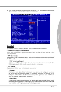
Fr-36 Carte mère MS-7666 Réglage BIOS Ce chapitre donne des informations concernant le programme de réglage de BIOS et vous permet de configurer le système pour obtenir des performances d’utilisation opti- mum. Vous aurez peut-être besoin de lancer le programme de réglage quand : Un message d’erreur...
Page 143 - Réglages d’Entrée; sera le menu principal.
Fr-37 Français Réglages d’Entrée Allumez l’ordinateur et le système lancera le processus POST (Test automatique d’allumage). Lorsque le message ci-dessous apparaît à l’écran, appuyez sur la touche <DEL> pour entrer dans les réglages. Press DEL to enter SETUP (Appuyez sur DEL pour entrer dans S...
Page 145 - Overclocking Profile (Profil d’overclocking)
Fr-39 Français M-Flash Utilisez ce menu pour lire/ flash le BIOS du lecteur de stockage (FAT/ FAT32 format uniquement). Overclocking Profile (Profil d’overclocking) Utilisez ce menu pour conserver/ charger vos réglages à/ de CMOS pour le BIOS. Load Fail-Safe Defaults (Défauts de sécurité de chargeme...
Page 146 - sur le site d’internet de MSI.
Fr-40 Carte mère MS-7666 Quand vous entrez dans l’unité de réglages BIOS, suivez les procédures suivantes pour l’utilisation générale. Load Optimized Defaults (Chargement des réglages par défaut optimisés) : Utilisez les touches de contrôle (↑↓ ) afin de surligner le domaine Load Optimized De- fault...
Page 153 - Résolution d’Overclocking échoué
Fr-47 Français Important Résolution d’Overclocking échoué Cette carte mère supporte fortement l’overclocking. Néanmoins, veuillez vous assurer que vos périphériques et composants peuvent supporter des réglages spéciaux. Aucu- ne opération qui dépasse les spécifications du produit n’est recommandée. ...
Page 154 - Information De Logiciel; haitez pour activer le dispositif.; meilleure performance du système.
Fr-48 Carte mère MS-7666 Information De Logiciel Sortez le pilote/ Service du DVD, qui est inclus dans le paquet de la carte mère et placez-le dans le DVD-ROM. L’installation va automatiquement se déclencher, cliquez sur le pilote ou sur l’usage et suivez le pop-up de l’écran pour accomplir l’instal...
Page 155 - Русский; Серия XPower
Page 156 - Характеристики
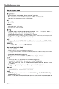
Ru-2 MS-7666 Системная плата Характеристики Процессоры Процессор Intel ® Bloomfield TM в конструктиве LGA1366 (Для получения самой новой информации о CPU, посетите сайт http://www.msi.com/index.php?func=cpuform2) QPI До 6.4 ГТ/с Чипсет Северный мост : Intel ® X58 Южный мост : Intel ® ICH10R Память 6...
Page 157 - Коннекторы
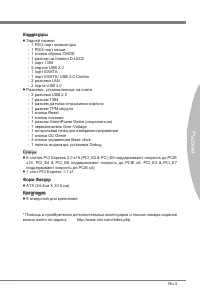
Ru-3 Русский Коннекторы Задней панели 1 PS/2 порт клавиатуры 1 PS/2 порт мыши 1 кнопка сброса CMOS 1 разъем на панели D-LED2 1 порт 1394 5 портов USB 2.0 1 порт ESATA 1 порт ESATA/ USB 2.0 Combo 2 разъема LAN 2 порта USB 3.0 Разъемы, установленные на плате 2 разъема USB 2.0 1 разъем 1394 1 разъем да...
Page 158 - Размещение компонентов системной платы
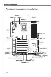
Ru-4 MS-7666 Системная плата OC Genie Размещение компонентов системной платы Задняя панель, Ru-14 CPU, Ru-5 CPUFAN, Ru-17 DDR3, Ru-9 Кнопка Reset, Ru-21 JPWR2, Ru-12 JPWR1, Ru-12 SYSFAN2, Ru-17 SATA, Ru-16 JFP1, JFP2, Ru-19 JUSB1~2, Ru-18 Кнопка управления Base Clock, Ru-22 КнопкаOC Genie, Ru-22 J13...
Page 159 - Внимание
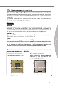
Ru-5 Русский CPU (Центральный процессор) При установке CPU, чтобы уберечь процессор от перегрева, не забудьте установить процессорный кулер. Если у вас нет процессорного кулера, пожалуйста, свяжитесь с дилером с целью приобретения и его установки до того, как включите компьютер. Последнюю информацию...
Page 160 - Установка процессора и вентилятора; Ключ для
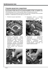
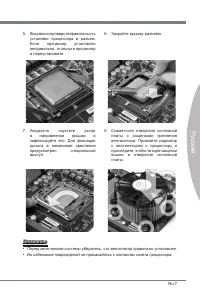
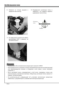
Ru-6 MS-7666 Системная плата Установка процессора и вентилятора Во избежание перегрева при работе обязательно установите вентилятор процессора. Одновременно, чтобы улучшить теплоотвод, убедитесь в том, что нанесён слой теплопроводящей пасты на процессоре перед установкой вентилятора. Следуйте данным...
Page 163 - информацией о совместимых компонентах обратитесь на сайт; Правила установки модулей памяти; Ниже приведены правила заполнения слотов памяти.
Ru-9 Русский Память Слоты DIMM используются для установки модулей памяти. За дополнительной информацией о совместимых компонентах обратитесь на сайт http://www.msi.com/index.php?func=testreport DDR3 240-конт, 1.5V 48x2=96 конт 72x2=144 конт Правила установки модулей памяти Ниже приведены правила зап...
Page 164 - Модули DDR3 не взаимозаменяемы с модулями DDR2, и стандарт DDR3 не
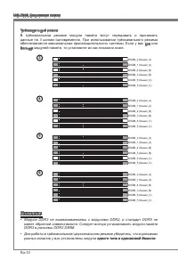
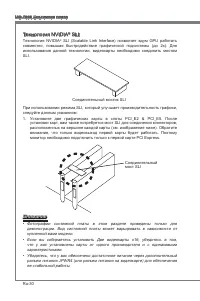
Ru-10 MS-7666 Системная плата Трёхканальный режим В трёхканальном режиме модули памяти могут передавать и принимать данные по 3 шинам одновременно. При использовании трёхканального режима обеспечивается максимальная производительность системы. Если у вас три или больше модулей памяти, то установите ...
Page 165 - памяти может максимально составить 23+ГБ (но не 24ГБ) при установке; Установка модулей памяти
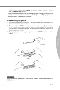
Ru-11 Русский Чтобы система загрузилась, вначале установите модули памяти в разъем DIMM_1 (DIMM_A0 в PCB v1.0).Из-за специфики распределения системных ресурсов чипсета, объём доступной памяти может максимально составить 23+ГБ (но не 24ГБ) при установке модулей памяти 4ГБ в каждый из слотов. Установк...
Page 166 - Разъем питания; Вы также можете использовать 20-контактный ATX блок питания. При
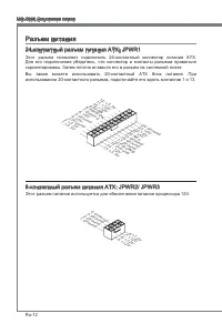
Ru-12 MS-7666 Системная плата Разъем питания 24-контактный разъем питания ATX: JPWR1 Этот разъем позволяет подключить 24-контактный коннектор питания ATX. Для его подключения убедитесь, что коннектор и контакты разъема правильно сориентированы. Затем плотно вставьте его в разъем на системной плате. ...
Page 168 - Задняя панель
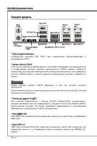
Ru-14 MS-7666 Системная плата Задняя панель Порт мыши/клавиатуры Стандартные разъемы DIN PS/2 ® для подключения мыши/клавиатуры с интерфейсом PS/2 ® . Кнопка сброса CMOS TНа плате установлена CMOS память с питанием от батарейки, хранящая данные о конфигурации системы. Данные, хранящиеся в CMOS памят...
Page 169 - Порт ESATA; Разъем LAN
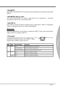
Ru-15 Русский Порт ESATA Порт ESATA (External SATA) используется для соединения с внешним устройством ESATA. Порт ESATA/ USB 2.0 Combo Этот порт ESATA/USB 2.0 combo используется для соединения с внешним устройством ESATA или устройством USB. Порт USB 3.0 Порт USB 3.0 является обратно совместимым уст...
Page 170 - работают на чипсете Intel; могут возникнуть потери данных при передаче.
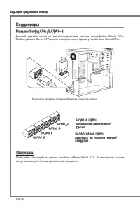
Ru-16 MS-7666 Системная плата Коннекторы Разъем Serial ATA: SATA1~8 Данный разъем является высокоскоростным портом интерфейса Serial ATA. Любой разъем Serial ATA может соединяться с одним устройством Serial ATA. * Компоненты системной платы в изображении только для справки. SATA5_6 SATA3_4 SATA1_2 S...
Page 172 - Разъем USB передней панели: JUSB1 / JUSB2; Разъем, соответствует спецификации Intel; Выносная планка USB 2.0; правильно подключены.; Разъем датчика открывания корпуса: JCI1
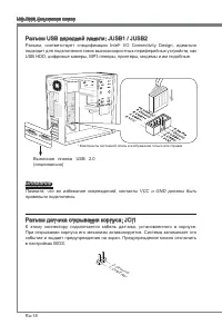
Ru-18 MS-7666 Системная плата Разъем USB передней панели: JUSB1 / JUSB2 Разъем, соответствует спецификации Intel ® I/O Connectivity Design, идеально подходит для подключения таких высокоскоростных периферийных устройств, как USB HDD, цифровые камеры, MP3 плееры, принтеры, модемы и им подобные. * Ком...
Page 173 - руководству Intel
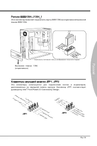
Ru-19 Русский Разъем IEEE1394: J1394_1 Этот коннектор позволяет подключить порты IEEE1394 на опциональной выносной планке IEEE1394. * Компоненты системной платы в изображении только для справки. Выносная планка 1394 (опционально) Коннекторы передней панели: JFP1, JFP2 Эти коннекторы используются для...
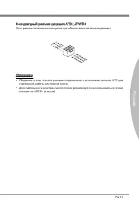
Page 174 - Разъем TPM Модуля: JTPM1; Данный разъем подключается к модулю TPM (Trusted Platform Module)
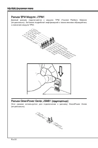
Ru-20 MS-7666 Системная плата Разъем TPM Модуля: JTPM1 Данный разъем подключается к модулю TPM (Trusted Platform Module) (опционально). За более подробной информацией и назначениями обращайтесь к описанию модуля TPM. 10.N o Pin 14.G roun d 8.5V Pow er 12.G roun d 6.Se rial IR Q 4.3.3 V Po wer 2.3V S...
Page 175 - возможности каждой из кнопок.; Кнопка питания; кнопку, чтобы включить или выключить систему; Кнопка перезагрузки; перезагрузить систему
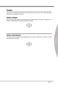
Ru-21 Русский Кнопки На этой системной плате имеются дополнительные кнопки. Эта глава поясняет возможности каждой из кнопок. Кнопка питания Эта кнопка используется для включения и выключения системы. Нажмите эту кнопку, чтобы включить или выключить систему . Кнопка перезагрузки Эта кнопка использует...
Page 176 - Кнопка OC Genie; параметры по умолчанию при следующей загрузке; МГц
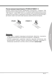
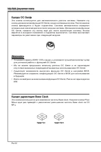
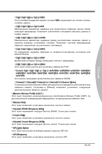
Ru-22 MS-7666 Системная плата Кнопка OC Genie Эта кнопка используется для автоматического разгона системы. Нажмите эту кнопку для включения функции OC Genie, когда система выключена. После нажатия кнопка фиксируется и будет подсвечена. Система автоматически определит оптимальные значения разгона пос...
Page 177 - Переключатель Over-Voltage
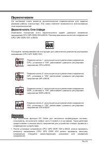
Ru-23 Русский Переключатели На системной плате имеются дополнительные переключатели для задания режимов работы компьютера. Эта глава поясняет возможности использования этих переключателей. Переключатель Over-Voltage Изменение положения этого переключателя задаёт диапазон изменения напряжений CPU/ QP...
Page 178 - Контрольная точка для измерения напряжения: V-Check Point
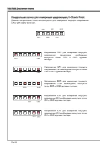
Ru-24 MS-7666 Системная плата Контрольная точка для измерения напряжения: V-Check Point Данные контрольные точки используются для измерения текущего напряжения CPU/ QPI/ DDR/ IOH/ ICH. CPU QPI DDR IOH ICH GND CPU GND Напряжение CPU: для измерения текущего напряжения процессора необходимо коснуться т...
Page 179 - Слот PCIE (Peripheral Component Interconnect Express); PCI Express x16 слот; установленными картами расширения или без них.
Ru-25 Русский Слоты Слот PCIE (Peripheral Component Interconnect Express) Слот PCI Express поддерживает карты расширения интерфейса PCI Express. PCI Express x16 слот PCI Express x1 слот Внимание Перед установкой или извлечением карт расширения убедитесь, что кабель питания отключен от электрической ...
Page 181 - Способ для установки четырёх карт расширения:
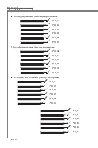
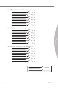
Ru-27 Русский Способ для установки четырёх карт расширения: PCI_E2 PCI_E3 PCI_E4 PCI_E5 PCI_E6 PCI_E7 Способ для установки пяти карт расширения: PCI_E2 PCI_E3 PCI_E4 PCI_E5 PCI_E6 PCI_E7 Способ для установки шести карт расширения: PCI_E2 PCI_E3 PCI_E4 PCI_E5 PCI_E6 PCI_E7 ■ ■ ■ Установленно Не устан...
Page 182 - Технология ATI CrossFireX
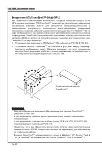
Ru-28 MS-7666 Системная плата Технология ATI CrossFireX TM (Multi-GPU) ATI CrossFireX TM обеспечивает возможность создания наиболее мощных multi- GPU игровых платформ. ATI CrossFireX TM позволяет двум или более графическим процессорам работать вместе для увеличения 3D-производительности и предоставл...
Page 183 - Система на базе CrossFireX; может работать в 4 режимах:
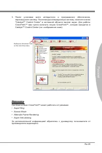
Ru-29 Русский Выберите Advanced View из the view drop menu. Внимание Система на базе CrossFireX TM может работать в 4 режимах: SuperTilingScissor ModeAlternate Frame RenderingSuper Anti-aliasing. За дополнительной информацией обратитесь к руководству пользователя от производителя видеокарты. •••• По...
Page 185 - подтверждающее сообщение Multi-GPU has been enabled.
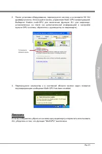
Ru-31 Русский Установитефлажок здесь Внимание Если вы собираетесь убрать из системы одну видеокарту и перестать использовать SLI, убедитесь в том, что функция “MultiGPU” выключена. После установки оборудования, перезагрузите систему и установите NV SLI драйвер/утилиты. Используйте панель управления ...
Page 189 - Панель индикаторов загрузки (Debug LED Panel)
Ru-35 Русский Панель индикаторов загрузки (Debug LED Panel) Сообщения индикатора загрузки (Debug LED) перечислены в таблице ниже. Код Состояние FF Включение питания и первичная инициализация CPU. C0, C1, C2 Этапы ранней инициализации CPU. C4, C6 Инициализация чипсета. D4, D5 Инициализация памяти. 08...
Page 190 - Настройка BIOS
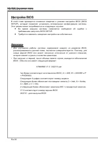
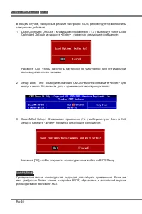
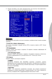
Ru-36 MS-7666 Системная плата Настройка BIOS В этой главе приводятся основные сведения о режиме настройки BIOS (BIOS SETUP), который позволяет установить оптимальную конфигурацию системы. Этот режим может потребоваться в следующих случаях: Во время загрузки системы появляется сообщение об ошибке с т...
Page 191 - Вход в режим настройки; Войдя в режим настройки, вы сразу увидите Главное меню.
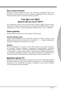
Ru-37 Русский Вход в режим настройки Включите питание компьютера. При этом запустится процедура POST (Тест включения питания). Когда на экране появится приведенное ниже сообщение, нажмите клавишу <DEL> для входа в режим настройки. Press DEL to enter SETUP (Нажмите DEL для входа в SETUP) Если с...
Page 201 - Восстановление после неудачного разгона
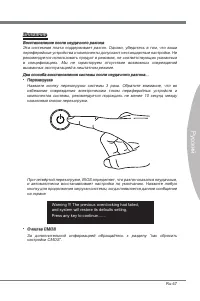
Ru-47 Русский Внимание Восстановление после неудачного разгона Эта системная плата поддерживает разгон. Однако, убедитесь в том, что ваши периферийные устройства и компоненты допускают нестандартные настройки. Не рекомендуется использовать продукт в режимах, не соответствующих указанным в спецификац...
Page 202 - Сведения о программном обеспечении; Установите драйверы для подключения необходимых устройств.; BIOS, которые позволят улучшить производительность системы.
Ru-48 MS-7666 Системная плата Сведения о программном обеспечении Установите в DVD привод диск Driver/Utility (Драйверы и утилиты) из комплекта поставки системной платы. Автоматически запустится инсталляция. Нажмите на название драйвера/ утилиты и следуйте инструкциям на экране для завершения инсталл...


 MSI 870-C45 V2series
User Manual
MSI 870-C45 V2series
User Manual
 MSI 970A-G45
User Manual
MSI 970A-G45
User Manual
 MSI B85-G43
User Manual
MSI B85-G43
User Manual
-User-Manual/webp/1.webp) MSI H67MA-E45 (B3)
User Manual
MSI H67MA-E45 (B3)
User Manual
 MSI Z77A-GD65 GAMING
User Manual
MSI Z77A-GD65 GAMING
User Manual
 MSI X99A MPOWER
User Manual
MSI X99A MPOWER
User Manual
 MSI G965MDH
User Manual
MSI G965MDH
User Manual
 MSI A55M-E33
User Manual
MSI A55M-E33
User Manual
 MSI MEGA651 PC
User Manual
MSI MEGA651 PC
User Manual
 MSI G41M-P33 Combo
User Manual
MSI G41M-P33 Combo
User Manual
 MSI MS-6391
User Manual
MSI MS-6391
User Manual
 MSI IM-945GSE SERIES MS-9830
User Manual
MSI IM-945GSE SERIES MS-9830
User Manual
 MSI K8NGM2-L
User Manual
MSI K8NGM2-L
User Manual
 MSI X99S XPOWER AC Manual
User Manual
MSI X99S XPOWER AC Manual
User Manual
 MSI GE60 0ND
User Manual
MSI GE60 0ND
User Manual
 MSI GE60 0ND-404BE
Manual
MSI GE60 0ND-404BE
Manual
 MSI H97I AC
Manual
MSI H97I AC
Manual
 MSI MS-7139
User Manual
MSI MS-7139
User Manual
 MSI B75MA-E31
User Manual
MSI B75MA-E31
User Manual
 MSI GE70 APACHE PRO
User Manual
MSI GE70 APACHE PRO
User Manual