MRCOOL MXH1518H24BV12 - Manuals
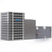
User Manual MRCOOL MXH1518H24BV12


Summary
Page 1 of 11 506318-03C mrcool.com Save these instructions for future reference INSTALLATION INSTRUCTIONS (R410A REFRIGERANT) (P) 506318-03C *P506318-03C* Manufactured By MRCOOL, LLC Hickory, KY 42051 This manual must be left with the homeowner for future reference. This is a safety alert symbol and...
506318-03C Page 2 of 11 mrcool.com NOTE: Maximum liquid-line size is 3/8 in. O.D. for all residential applications including long lines. Outdoor Section Zoning ordinances may govern the minimum distance the condensing unit can be installed from the property line. Install on a Solid, Level Mounting P...
Page 3 of 11 506318-03C mrcool.com Figure 1. DO LOCATE THE UNIT: • With proper clearances on sides and top of unit • On a solid, level foundation or pad • To minimize refrigerant line lengths DO NOT LOCATE THE UNIT: • On brick, concrete blocks or unstable surfaces • Near clothes dryer exhaust vents ...
MRCOOL Air Conditioners Manuals
-
 MRCOOL A-09-HP-115B-LG
User Manual
MRCOOL A-09-HP-115B-LG
User Manual
-
 MRCOOL A-09-HP-115B-MS
User Manual
MRCOOL A-09-HP-115B-MS
User Manual
-
 MRCOOL A-09-HP-115C
User Manual
MRCOOL A-09-HP-115C
User Manual
-
MRCOOL A-09-HP-115C-MS
User Manual
-
 MRCOOL A-09-HP-230B-LG
User Manual
MRCOOL A-09-HP-230B-LG
User Manual
-
 MRCOOL A-09-HP-230B-MS
User Manual
MRCOOL A-09-HP-230B-MS
User Manual
-
MRCOOL A-09-HP-230C
User Manual
-
MRCOOL A-09-HP-230C-MS
User Manual
-
 MRCOOL A-12-HP-115B-LG
User Manual
MRCOOL A-12-HP-115B-LG
User Manual
-
 MRCOOL A-12-HP-115B-MS
User Manual
MRCOOL A-12-HP-115B-MS
User Manual
-
 MRCOOL A-12-HP-115C
User Manual
MRCOOL A-12-HP-115C
User Manual
-
 MRCOOL A-12-HP-115C-MS
User Manual
MRCOOL A-12-HP-115C-MS
User Manual
-
 MRCOOL A-12-HP-230B-LG
User Manual
MRCOOL A-12-HP-230B-LG
User Manual
-
 MRCOOL A-12-HP-230B-MS
User Manual
MRCOOL A-12-HP-230B-MS
User Manual
-
MRCOOL A-12-HP-230C
User Manual
-
MRCOOL A-12-HP-230C-MS
User Manual
-
 MRCOOL A-18-HP-230B-LG
User Manual
MRCOOL A-18-HP-230B-LG
User Manual
-
 MRCOOL A-18-HP-230B-MS
User Manual
MRCOOL A-18-HP-230B-MS
User Manual
-
MRCOOL A-18-HP-230C
User Manual
-
MRCOOL A-18-HP-230C-MS
User Manual