Page 2 - Contents
Contents 2 IMPORTANT SAFETY INSTRUCTIONS ................................................................. 4 Caring for the environment ................................................................................. 13 Description of functions .........................................................
Page 3 - Exhaust duct
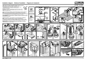
Contents 3 Drilling diagram for wall mounting ......................................................................... 36 Plywood backing .................................................................................................. 37 To install a plywood backing .................................
Page 4 - IMPORTANT SAFETY INSTRUCTIONS; Use
IMPORTANT SAFETY INSTRUCTIONS 4 READ AND SAVE THESE INSTRUCTIONS This appliance complies with current safety requirements. Improper use of the appliance can lead to personal injury and material damage. Read all instructions before installing or using the appliance for the first time. Only use the ap...
Page 5 - Children
IMPORTANT SAFETY INSTRUCTIONS 5 Children As with any appliance, close supervision is necessary when used by children. Please supervise children in the vicinity of the hood and do not let them play with it. Danger of suffocation! Ensure that any plastic wrappings, bags, etc. are disposed of saf...
Page 7 - Proper use
IMPORTANT SAFETY INSTRUCTIONS 7 Defective components should be replaced by Miele original parts only. Only with these parts can the manufacturer guarantee the safety of the appliance. If the power cord is damaged, it must only be replaced by a qualified service technician. During installation,...
Page 10 - Proper installation
IMPORTANT SAFETY INSTRUCTIONS 10 Proper installation WARNING: TO REDUCE THE RISK OF FIRE, ELECTRIC SHOCK, OR INJURY TO PERSONS, OBSERVE THE FOLLOWING: – a) Installation work and electrical wiring must be done by qualified person(s) in accordance with all applicable codes and standards, including f...
Page 12 - Cleaning and care
IMPORTANT SAFETY INSTRUCTIONS 12 Cleaning and care Never use a steam cleaner to clean the ventilation hood. The steam can reach the electrical components and cause a short circuit. Accessories Use only genuine original Miele parts. If parts or accessories from other manufacturers are used, the w...
Page 13 - Caring for the environment; Disposal of the packing
Caring for the environment 13 Disposal of the packing material The cardboard box and packing materials protect the appliance during shipping. They have been designed to be biodegradable and recyclable.Ensure that any plastic wrappings, bags, etc. are disposed of safely and kept out of the reach of c...
Page 14 - Description of functions; Vented mode
Description of functions 14 The following functions are available on your ventilation hood, depending on the model: Vented mode The air is drawn into the ventilation hood. It is then cleaned by the edge extraction panels and the grease filters and directed outside. Non-return flap A non-return flap ...
Page 16 - Guide to the appliance
Page 18 - Reaction time
Operation (Automatic mode) 18 When Con@ctivity 2.0 is active, the hood always operates in Automatic mode (see "Activating Con@ctivity 2.0").See "Cooking without Con@ctivity 2.0" for information on manually operating the hood. Cooking with Con@ctivity 2.0 (Automatic mode) Turn on a ...
Page 20 - before
Operation (Automatic mode) 20 Temporarily exiting Automatic mode To temporarily exit the Automatic mode when cooking: Manually select a different fan level, or Manually turn the hood off, or Activate the Delayed shut down function on the ventilation hood. The fan turns off after the delay ti...
Page 22 - Power management; Turning power management On/Off
Operation (Manual mode) 22 Power management The ventilation hood features a power management system for switching off the lighting and reducing the fan power setting automatically. – If the intensive setting is selected, the fan automatically switches to level 3 after 5 minutes. – If the fan is set ...
Page 23 - Filter saturation indicator; Adjusting the filter saturation
Operation (Automatic and Manual modes) 23 Filter saturation indicator The number of hours the hood has been in operation is stored in appliance memory.The filter saturation indicators show when the filters need to be cleaned or changed by lighting up the grease filter symbol or OdorFree Charcoal F...
Page 25 - Stainless steel housing; General
Cleaning and care 25 WARNING: TO REDUCE THE RISK OF FIRE, ELECTRIC SHOCK, OR INJURY TO PERSONS, OBSERVE THE FOLLOWING: Before cleaning or servicing the hood, disconnect it from the power supply, see "IMPORTANT SAFETY INSTRUCTIONS". Stainless steel housing General The surfaces and control b...
Page 26 - Special instructions for control; Panels and grease filters for; Cleaning intervals
Cleaning and care 26 Special instructions for control buttons Do not leave dirt and debris on the buttons for any length of time.Otherwise they may become discolored or damaged.Remove any dirt or debris immediately. Observe the general cleaning instructions contained in this chapter. Do not use a ...
Page 27 - Removing the panels and grease
Cleaning and care 27 Removing the panels and grease filters The grease filters and panels can fall out when you are handling them.This can result in damage.Make sure you hold the filters and panels securely at all times when handling them. Pull the front edge of the panels down out of the lock, lo...
Page 28 - Cleaning the panels and grease; OdorFree Charcoal Filter
Cleaning and care 28 Cleaning the panels and grease filters in the dishwasher Place the panels and filters as upright or inclined as possible in the lower basket. Ensure that the spray arm is not obstructed. Use a household dishwasher detergent. Select a program with a wash temperature between...
Page 29 - Installing/replacing the OdorFree
Cleaning and care 29 Installing/replacing the OdorFree Charcoal Filter To install or replace the OdorFree Charcoal Filter, the grease filters must first be removed as described above. Remove the OdorFree Charcoal Filter from its packaging. Slide the filter into the back of the intake frame, th...
Page 30 - Resetting the filter saturation
Cleaning and care 30 Resetting the filter saturation counter for the filter If the filter saturation counter is activated, it must be reset each time the filter is changed. To do this, press the filter saturation indicator twice with the fan turned on and hold it for approx. 3 seconds until 1 i...
Page 31 - Installation; Before installation
Installation 31 Before installation Before installing the appliance, read all of the information contained in this chapter and also in the "IMPORTANT SAFETY INSTRUCTIONS" section. Removing the protective film The housing components are covered by a protective film to prevent them from beco...
Page 32 - Installation parts
Page 34 - Appliance dimensions; Extraction
Installation 34 Appliance dimensions The drawing is not to scale. a Extraction b Recirculation (only DA 6596 W) c Air vent positioned at the top for recirculation
Page 35 - Distance between cooktop and ventilation hood (S)
Installation 35 de Installation area (only d is required for recirculation ventilation hoods). Wall and ceiling area for exhaust duct opening and for wall socket installation. Only the wall socket installation is required for recirculation hoods. Vent collar 6" (150 mm), with adapter 5" ...
Page 36 - Installation recommendations
Installation 36 Installation recommendations – We also recommend a distance of at least 25 1/2" (650 mm) above electric cooktops to provide more workspace and easier cooking under the hood. – When selecting an installation height, always take the user height into consideration. Users should have...
Page 37 - Plywood backing
Installation 37 Plywood backing The majority of the weight of the installed ventilation system will be supported by the lower retaining plate. It must be firmly attached to the stud framing behind the drywall. If studs are not available in the required locations, a plywood backing (min. ½ " (13 ...
Page 39 - Condensate trap
Exhaust duct 39 Condensate trap In addition to insulating the exhaust duct, we recommend installing a condensate trap to collect and evaporate any condensate which might accumulate. Condensate traps are available for exhaust ducts with a diameter of 5" (125 mm) or 6" (150 mm). When install...
Page 40 - Electrical connection; Grounding Instructions
Electrical connection 40 WARNING: TO REDUCE THE RISK OF FIRE, ELECTRIC SHOCK, OR INJURY TO PERSONS, OBSERVE THE FOLLOWING:All electrical work should be performed by a qualified electrician in strict accordance with national regulations (for USA: ANSI-NFPA 70) and local safety regulations. Installati...
Page 41 - Installation of the Con@ctivity; Activating the ventilation hood
Activating Con@ctivity 2.0 41 Installation of the Con@ctivity 2.0 stick In order for you to be able to use the Con@ctivity 2.0 function, the cooktop must be equipped with a Con@ctivity 2.0 stick. See the relevant installation instructions of the Con@ctivity 2.0 stick. Activating Con@ctivity 2.0 To...
Page 42 - Checking activation
Activating Con@ctivity 2.0 42 The Con@ctivity 2.0 function is now ready for use.If you do not confirm within 4 minutes, activation will be canceled. Checking activation To check whether Con@ctivity 2.0 has been activated for the hood: Turn off the fan and cooktop lighting. Press the Delayed shut...
Page 43 - Service and warranty; Location of the data plate
Service and warranty 43 For faults that you cannot resolve on your own, please contact your Miele dealer or Miele Technical Service.The telephone number for the Technical Service Department is listed at the back of these instructions.When contacting Miele, please state the model and serial number of...
Page 44 - Technical data
Technical data 44 Fan motor 350 W Cooktop lighting 3 x 3 W Total connected load 359 W Voltage, Frequency 120 V AC, 60 Hz Fuse rating 15 A Power cord length 2.5 ft (0.75 m) WeightDA 6596 W 55 lbs (25 kg) DA 6526 W 61.6 lbs (28 kg) Optional accessories for recirculation mode: Recirculation kit DUW 20 ...
Page 45 - National Headquarters; Canada; Headquarters and Miele Centre
9 Independence WayPrinceton, NJ 08540Phone: Fax:www.mieleusa.com U.S.A. Miele, Inc. National Headquarters Please have the model and serial numberof your appliance available beforecontacting Technical Service. Canada ImporterMiele Limited Headquarters and Miele Centre 800-843-7231609-419-9898609-419-...