Page 2 - ENGLISH; Emphasizes essential information.; ATTENTION; Souligne des informations importantes.
2 INDEX INHALTSVERZEICHNIS INDEX INDICE INDICE ENGLISH Page 3 to 16 Page DEUTSCH Page 17 to 30 Page FRANÇAIS Page 31 to 44 Page ITALIANO Page 45 to 58 Page ESPAÑOL Page 59 to 72 Page DEFINITIONS OF SIGNAL WORDSWARNING: Indicates a potentially hazardous situation which, if not avoided, could result i...
Page 3 - BEFORE USING THIS TOOL, STUDY THIS MANUAL TO ENSURE SAFETY WARNING
3 ENGLISH HN120 HIGH PRESSURE CONCRETE TOOL INDEX 1. SAFETY INSTRUCTIONS …………… 4 2. SPECIFICATIONS & TECHNICAL DATA …………………… 7 3. AIR SUPPLY AND CONNECTIONS … 9 4. INSTRUCTIONS FOR OPERATION … 10 5. MAINTAIN FOR PERFORMANCE … 16 6. STORING …………………………… 16 7. TROUBLESHOOTING/REPAIRS …… 16 OPERATIN...
Page 4 - SAFETY INSTRUCTIONS; PRECAUTIONS ON USING THE TOOL
4 1. SAFETY INSTRUCTIONS PRECAUTIONS ON USING THE TOOL 1. WEAR SAFETY GLASSES OR GOGGLES Danger to the eyes always exists due to the possibility of dust being blown up by the exhausted airor of a fastener flying up due to the improper handling of the tool. For these reasons, safety glassesor goggles...
Page 6 - OBSERVE THE FOLLOWING GENERAL CAUTION IN ADDITION TO
6 18. WHEN USING THE TOOL OUTSIDE OR ELEVATED PLACE When fastening roofs or similar slanted surface, start fastening at the lower part and gradually workyour way up. Fastening backward is dangerous as you may loose your foot place.Secure the hose at a point close to the area you are going to drive f...
Page 7 - SPECIFICATIONS AND TECHNICAL DATA; TOOL SPECIFICATIONS
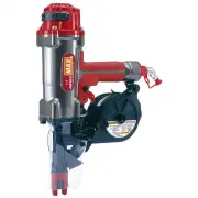
7 2. SPECIFICATIONS AND TECHNICAL DATA 1. NAME OF PARTS 2. TOOL SPECIFICATIONS PRODUCT NO. HN120 HEIGHT 15-3/4˝ (400 mm) WIDTH 3-3/8˝ (85 mm) LENGTH 12-3/8˝ (315 mm) WEIGHT 6.4 lbs. (2.9 kg) RECOMMENDED 210 to 320 p.s.i. (15 to 23 bar) OPERATING PRESSURE LOADING CAPACITY 50 Nails AIR CONSUMPTION 4.7...
Page 8 - Vibration characteristic value
8 4. TECHNICAL DATA q NOISE A-weighted single-event ------ LWA, 1s, d 110.0 dBsound power levelA-weighted single-event ------ L p A , 1s, d 97.5 dBemission sound pressurelevel at work stationThese values are determined and documented in accordance to EN12549 : 1999. w VIBRATION Vibration characteris...
Page 9 - AIR SUPPLY AND CONNECTIONS; Read section titled “SAFETY INSTRUCTIONS”.; DO NOT USE ANY POWER SOURCE EXCEPT AN AIR COMPRESSOR
9 WHEN USING THE TOOL, BE SURE TO USE A SPECIAL AIR COMPRESSORAND AIR HOSE. In order to improve its performance, it has set its working pressure higher than theconventional nailers. To use the tool, you always need the special air compressor andair hose (MAX PowerLite Compressor and MAX PowerLite Ho...
Page 10 - INSTRUCTIONS FOR OPERATION; BEFORE OPERATION; OPERATION
4. INSTRUCTIONS FOR OPERATION Read section titled “SAFETY INSTRUCTIONS”. 1. BEFORE OPERATION q Wear Safety Glasses or Goggles. w Do not connect the air supply. e Inspect screw tightness. r Check operation of the contact arm & trigger if moving smoothly. t Connect the air supply. y Check the air-...
Page 11 - Push the door lever to open the door.
11 r Determine the magazine direction in tune with the length of pins (or nails) used, fitthe magazine collar into the groove in the magazine holder, set the magazine hookonto its mating part, and push the magazine lock lever to secure the magazine. t Push the magazine cap lever. With the magazine c...
Page 12 - MODEL IDENTIFICATION; Identified by
12 i Push the door to close it. o Close the magazine cap. !0 Connect the air chuck to the air plug. You are now ready to drive the pins (or nails). Door MODEL IDENTIFICATION SEQUENTIAL TRIP The Sequential Trip requires the operator to hold the tool against the work before pulling the trigger. Thisma...
Page 13 - HOW TO REMOVE PLASTIC SHEET
13 REPLACING THE ATTACHMENT The machine comes with the attachments B and C as accessories. See the following forthe replacement method. When replacing the attachment, be sure to lock a trigger and remove an air hose. PROCEDURE q Remove the attachment A which has been attached at shipment; hold and d...
Page 14 - TROUBLESHOOTING; If not activated, apply 5 to 6 oil drips from the air plug.; HOW TO REMOVE JAMMING OF PINS/NAILS; Lock the trigger and disconnect the air hose.
14 Hammer Punch r Remove the pins (or nails) jamming inside the nose, using the punch or a regularscrewdriver. t Set the pins (or nails) properly onto the feed pawl again and close the door. Regular screwdriver TROUBLESHOOTING ● The Machine is not activated even if it is operated correctly. When the...
Page 15 - APPLICATIONS AND PINS/NAILS SELECTION CRITERIA; Application
15 APPLICATIONS AND PINS/NAILS SELECTION CRITERIA The Machine is applicable to the following purposes. When using it, select the pins/nails and leg length suitable for the drivingobject. Application Type Size (Leg Length) Attachment Used Securing a thin steel plateto the concreteEx.: Securing partit...
Page 16 - MAINTAIN FOR PERFORMANCE; DO NOT FIRE THE NAILER WHEN IT IS EMPTY
16 5. MAINTAIN FOR PERFORMANCE q DO NOT FIRE THE NAILER WHEN IT IS EMPTY w USE RECOMMENDED OIL The velocite or turbine oil should be used to lubricate the tool. Upon completion of operations, place 2or 3 drops of oil into the air plug inlet with the jet oiler. (Recommended Oil : ISO VG32) e INSPECT ...