Makita UB1103 - Manuals

User Manual Makita UB1103


Summary
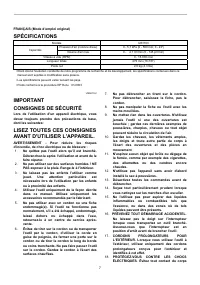
2 ENGLISH (Original instructions) SPECIFICATIONS Model UB1103 Air pressure (water column) 0 - 5.7 kPa (0 - 580 mm; 0 - 23") Capacities Max. air volume 0 - 4.1 m 3 /min (0 - 145cu.ft./min) No load speed (RPM) 0 - 16,000 /min Overall length 479 mm (18-7/8") Net weight 2.0 kg (4.3 lbs) • Due to...
3 SERVICING OF DOUBLE INSULATED APPLIANCES In a double-insulated appliance, two systems of insulation are provided instead of grounding. No grounding means is provided on a double-insulated appliance, nor should a means for grounding be added to the appliance. Servicing a double-insulated appliance ...
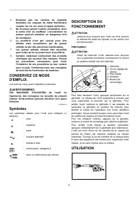
4 USD201-2 Symbols The followings show the symbols used for tool. ・ volts ・ amperes ・ hertz ・ alternating current ・ no load speed ・ Class II Construction ・ revolutions or reciprocation per minute FUNCTIONAL DESCRIPTION CAUTION: • Always be sure that the tool is switched off and unplugged before adju...
Manual Makita UB1103


Summary
P 2 / 8 R epair It is not required to lubricate, because the product has no gear mechanism to be lubricated. [3] DISASSEMBLY/ASSEMBLY [3] -1. Switch CAUTION: Repair the machine in accordance with “Instruction manual” or “Safety instructions”. [1] NECESSARY REPAIRING TOOLS [2] LUBRICATION Fig. 1 DISA...
P 3 / 8 R epair [3] DISASSEMBLY/ASSEMBLY [3] -2. Fan Section DISASSEMBLING Disassemble Fan 110 as drawn in Fig. 2 . Assemble Fan Section by reversing the disassembly procedure. Refer to Fig. 2 . Note: Align the hole on Set plate with the protrusion on Fan cover, and insert Set plate by hand, then pu...
P 7 / 8 C ircuit diagram W iring diagram Fig. D-1 Fig. D-2 White Noise suppressor Switch viewed from Commutator side Brush holder B Brush holder A Line filter Power supply cord Color index of lead wires' sheath Black Blue Brown Field connected to Switch Field Motor housing complete Wiring of Field l...
Makita Leaf Blowers Manuals
-
 Makita DUB183Z
User Manual
Makita DUB183Z
User Manual
-
 Makita GBU01M1
User Manual
Makita GBU01M1
User Manual
-
 Makita GBU01M1-BL4040
User Manual
Makita GBU01M1-BL4040
User Manual
-
 Makita GBU01Z
User Manual
Makita GBU01Z
User Manual
-
 Makita XBU01Z
Manual
Makita XBU01Z
Manual
-
 Makita XBU02PT
User Manual
Makita XBU02PT
User Manual
-
 Makita XBU02PT1
User Manual
Makita XBU02PT1
User Manual
-
 Makita XBU02Z
User Manual
Makita XBU02Z
User Manual
-
 Makita XBU03SM1
User Manual
Makita XBU03SM1
User Manual
-
 Makita XBU03Z
User Manual
Makita XBU03Z
User Manual
-
 Makita XBU04PTV
User Manual
Makita XBU04PTV
User Manual
-
 Makita XBU04ZV
User Manual
Makita XBU04ZV
User Manual