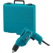
Makita DS4011 - Manuals
User Manual Makita DS4011


Summary
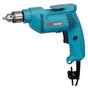
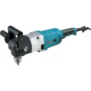
2 ENGLISH (Original instructions) SPECIFICATIONS Model DS4011 DS5000 Steel 13 mm (1/2") 16 mm (5/8") Capacities Wood 36 mm (1-7/16") No load speed (RPM) 600/min. Overall length 340 mm (13-3/8") 348 mm (13-3/4") Net weight 2.8 kg (6.3 lbs) 3.0 kg (6.6 lbs) • Due to our continuing ...
3 16. If devices are provided for the connection of dust extraction and collection facilities, ensure these are connected and properly used. Use of dust collection can reduce dust-related hazards. Power tool use and care 17. Do not force the power tool. Use the correct power tool for your applicatio...
4 SAVE THESE INSTRUCTIONS. WARNING: DO NOT let comfort or familiarity with product (gained from repeated use) replace strict adherence to safety rules for the subject product. MISUSE or failure to follow the safety rules stated in this instruction manual may cause serious personal injury. USD201-2 S...
Manual Makita DS4011


Summary
P 2 / 8 R epair CAUTION: Repair the machine in accordance with “Instruction manual” or “Safety instructions”. [1] NECESSARY REPAIRING TOOLS [2] LUBRICATIONS Fig. 1 Code No. Description Use for 1R139 Drill chuck extractor Removing / Assembling Drill chuck 1R223 Torque wrench shaft 20-90 N.m Removing ...
P 3 / 8 R epair [3]-2. Drill chuck, Gear, Spindle Fig. 4 Fig. 6 1R139 2. Fit the flats of Spindle to the notch of 1R139 and then hold 1R139 in vise. 3. Attach 1R224 and 1R298 to 1R223 and then secure 1R298 with Drill chuck. 4. Turn 1R223 counterclockwise. 1. Hold Drill chuck in vise. 2. Fit the flat...
P 5 / 8 R epair (1) Assemble Gear section as illustrated in Figs. 10 and 11 . [3] DISASSEMBLY/ASSEMBLY [3]-2. Gear, Spindle Fig. 10 Fig. 9 4. Set Pin 3 in place to assemble Gasket and Gear housing cover complete precisely to Gear housing complete in the next step. 5. Align the holes of Gasket and th...
Makita Drills Manuals
-
 Makita 6407
User Manual
Makita 6407
User Manual
-
Makita 6407
Manual
-
 Makita 6501
User Manual
Makita 6501
User Manual
-
Makita 6501
Manual
-
 Makita 6300-4
User Manual
Makita 6300-4
User Manual
-
 Makita 6302H
User Manual
Makita 6302H
User Manual
-
Makita 6302H
Manual
-
 Makita 6408K
User Manual
Makita 6408K
User Manual
-
Makita 6408K
Manual
-
 Makita AD03R1
User Manual
Makita AD03R1
User Manual
-
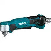 Makita AD03Z
User Manual
Makita AD03Z
User Manual
-
 Makita AD04R1
User Manual
Makita AD04R1
User Manual
-
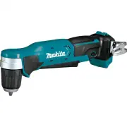 Makita AD04Z
User Manual
Makita AD04Z
User Manual
-
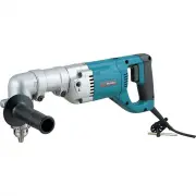 Makita DA4000LR
User Manual
Makita DA4000LR
User Manual
-
Makita DA4000LR
Manual
-
 Makita DA4031
User Manual
Makita DA4031
User Manual
-
Makita DA4031
Manual
-
 Makita DDA350Z
User Manual
Makita DDA350Z
User Manual
-
 Makita DP2010
User Manual
Makita DP2010
User Manual
-
 Makita DP3003
User Manual
Makita DP3003
User Manual