LG LP153HDUC - Manuals
LG LP153HDUC Air Conditioner – User Manual in PDF format online.
Manuals:
User Manual LG LP153HDUC


Summary
2 Room Air Conditioner Packaged Terminal Air Conditioner/Heat Pump Owner's Manual TABLE OF CONTENTS FOR YOUR RECORDS Write the model and serial numbers here: Model #Serial # Dealer's NameDate Purchased Staple your receipt to this page in the event you need it to prove date of purchase or for warrant...
Ownerʼs Manual 3 ENGLISH Safety Precautions Safety Precautions Incorrect operation due to ignoring instruction will cause harm or damage. The seriousnessis classified by the following indications. Meanings of symbols used in this manual are as shown below. WARNING CAUTION This symbol indicates the p...
4 Room Air Conditioner Safety Precautions n Operation Do not place the power cord near a heater. • It may cause fire and electric shock. Do not allow water to run into electric parts. • It will cause failure of machine or electric shock. Use a soft cloth to clean. Do not use wax, thinner, or a stron...
LG Air Conditioners Manuals
-
 LG B24TS
User Manual
LG B24TS
User Manual
-
LG B24TS
Manual
-
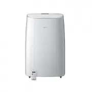
 LG LP0621WSR
User Manual
LG LP0621WSR
User Manual
-
 LG LP0721WSR
User Manual
LG LP0721WSR
User Manual
-
 LG LP0821GSSM
User Manual
LG LP0821GSSM
User Manual
-
 LG LP1021BHSM
User Manual
LG LP1021BHSM
User Manual
-
 LG LP1021BSSM
User Manual
LG LP1021BSSM
User Manual
-
 LG LP1419IVSM
User Manual
LG LP1419IVSM
User Manual
-
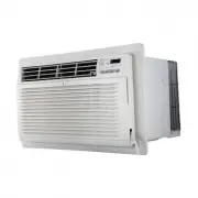 LG LT1016CER
User Manual
LG LT1016CER
User Manual
-
 LG LT1216CER
User Manual
LG LT1216CER
User Manual
-
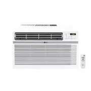 LG LW1016ER
User Manual
LG LW1016ER
User Manual
-
 LG LW1017ERSM
User Manual
LG LW1017ERSM
User Manual
-
 LG LW1017ERSM1
User Manual
LG LW1017ERSM1
User Manual
-
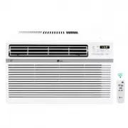
 LG LW1216ER
User Manual
LG LW1216ER
User Manual
-
 LG LW1217ERSM1
User Manual
LG LW1217ERSM1
User Manual
-
 LG LW1221HRSM
User Manual
LG LW1221HRSM
User Manual
-
 LG LW1223HR
User Manual
LG LW1223HR
User Manual
-
 LG LW1516ER
User Manual
LG LW1516ER
User Manual
-
 LG LW1521ERSM1
User Manual
LG LW1521ERSM1
User Manual
-
 LG LW1816ER
User Manual
LG LW1816ER
User Manual