Page 2 - On Safety; Do not Open the Display.; Important Precautions
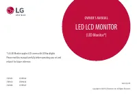
A1 This unit has been engineered and manufactured to ensure your personalsafety, however improper use may result in potential electrical shock or firehazards. In order to allow the proper operation of all safeguardsincorporated in this display, observe the following basic rules for itsinstallation, ...
Page 3 - On Installation; screen because over-spraying may cause electrical shock.; On Repacking
A2 Important Precautions On Installation Do not allow anything to rest upon or roll over the power cord, and do not placethe display where the power cord is subject to damage. Do not use this display near water such as near a bathtub, washbowl, kitchensink, laundry tub, in a wet basement, or near a ...
Page 4 - Connecting the speaker; Place the monitor with its front facing downward on a soft cloth.; Connecting the speakers -; The feature is only for speaker models - L226WTM; Cable
A3 Connecting the speaker 1 . Place the monitor with its front facing downward on a soft cloth. 2 . Insert the protruding hook of the speaker in the direction of the slot in the back of the product. Connecting the speakers - The feature is only for speaker models - L226WTM Hook Slot Audio DC-In Cabl...
Page 5 - Connecting the Display; Important; Connecting the stand
A4 Connecting the Display Important This illustration depicts the general model of connection. Your monitor may differ fromthe items shown in the picture.Do not carry the product upside down holding only the stand base. The product mayfall and get damaged or injure your foot. Before setting up the m...
Page 6 - Pushing Latch inside, Take the stand base from stand body.
Connecting the Display A5 Disassembling the standType. A 1. Put a cushion or soft cloth on aflatsurface. 3. Pushing Latch inside, Take the stand base from stand body. 5. Pack up the product as shown in the picture. 4. Separate the stand using a screwdriver as shown in the picture. Note: Please keep ...
Page 7 - Pull out the Stand to remove.
A6 Connecting the Display Disassembling the standType. B 1. Put a cushion or soft cloth on aflatsurface. 3. Change your hold on the product as it follows and turn the Stand Base in the arrow direction. 5. Pushing Latch inside, Take the standbase from stand body. 6. Pack up the product as shown in th...
Page 8 - Positioning your display; Ergonomic
A7 Connecting the Display 20 Before setting up the monitor, ensure that the power to the monitor, the computersystem, and other attached devices is turned off. Positioning your display 1. Adjust the position of the panel in various ways for maximum comfort. Tilt Range : -5˚~20˚ Ergonomic It is recom...
Page 9 - Using the Computer; to; NOTE; Connect DVI Cable
A8 Using the Computer 1. Make sure to turn off the computer and product. Connect the cable as below sketch mapform to . 1 2. Press button on the front switch panel to turn the power on. When monitor power is turned on, the 'Self Image Setting Function' is executed automatically. (Only Analog Mode) N...
Page 10 - Using the speakers -; Side Jack; Headphone/Earphone Input
A9 Using the speakers - The feature is only for speaker models - L226WTM Side Jack Rear AUDIO IN Headphone/Earphone Input Connects to the *LINE OUT jack of thePC sound card. *Line Out Speaker Out <Jack of the PC sound card>
Page 11 - Control Panel Functions; ZOOMING; Recommend resolution are 1680; Control; MENU Button; Use this button to enter or exit the On Screen Display.; The message; MENU button; for several seconds. The message; Front Panel Controls
A10 Control Panel Functions ZOOMING At the current display, Use 'ez Zooming' Key, then the displayresolution is transferred to the one step low resolution.Use 'ez Zooming' Key one more, the display is back to theoriginal display. *Only One touch of ez-zoom, you can fine the best resolutionyou want a...
Page 12 - Use this button to turn the display on or off.; Power Button; button before entering the On Screen; Buttons
A11 Control Panel Functions This Indicator lights up blue when the displayoperates normally(On Mode). If the display is in SleepMode (Energy Saving), this indicator color changes to amber. Use this button to turn the display on or off. Power Button Power Indicator Use this button to enter a selectio...
Page 13 - On Screen Display (OSD) Control Adjustment; Screen Adjustment
A12 On Screen Display (OSD) Control Adjustment Screen Adjustment Making adjustments to the image size, position and operating parameters ofthe display is quick and easy with the On Screen Display Control system. A short example is given below to familiarize you with the use of the controls.The follo...
Page 14 - The order of icons may differ depending on the model (A1; On Screen Display(OSD) Selection and Adjustment; PICTURE; POSITION VERTICAL; FLATRON
A13 NOTE The order of icons may differ depending on the model (A1 3 ~A17 ). On Screen Display(OSD) Selection and Adjustment The following table indicates all the On Screen Display control, adjustment,and setting menus. To adjust the brightness,contrast and gamma of thescreen PICTURE COLOR POSITION T...
Page 15 - Press the MENU Button, then the main menu of the OSD appears.; P I C T U R E
A14 On Screen Display(OSD) Selection and Adjustment NOTE OSD (On Screen Display) menu languages on the monitor may differ from the manual. You were introduced to the procedure of selecting and adjusting an itemusing the OSD system. Listed below are the icons, icon names, and icondescriptions of the ...
Page 16 - Main menu
A15 MENU : Exit : Decrease : Increase SET : Select another sub-menu On Screen Display(OSD) Selection and Adjustment Main menu Sub menu Description BRIGHTNESS CONTRAST GAMMA To adjust the brightness of the screen. To adjust the contrast of the screen. Set your own gamma value. : -50/0/50On the monito...
Page 17 - TRACKING
A16 Press the button to reset immediately. MENU : Exit : Decrease : Increase SET : Select another sub-menu On Screen Display(OSD) Selection and Adjustment Main menu Sub menu Description CLOCK PHASE SHARPNESS To minimize any vertical bars or stripesvisible on the screen background.The horizontal scre...
Page 19 - Troubleshooting; Check the following before calling for service.; No image appears
A18 Troubleshooting No image appears Check the following before calling for service. No image appears Do you see a "OSD LOCKED" message on the screen? ● Is the power cord of the display connected? ● Is the power indicator light on? ● Is the power on and the power indicator blue orgreen? ● Is...
Page 20 - Display image is incorrect
A19 Troubleshooting Display image is incorrect ● Display Position is incorrect. ● On the screen background, verticalbars or stripes arevisible. ● Any horizontal noise appearing in anyimage or charactersare not clearlyportrayed. • Press the AUTO/SET button to automatically adjust your display image t...
Page 21 - Have you installed the display driver?; Have you installed the; The screen color is
A20 Troubleshooting Have you installed the display driver? ● Have you installed the display driver? ● Do you see an "Unrecognized monitor,Plug&Play (VESA DDC)monitor found"message? • Be sure to install the display driver from the display driver CD (or diskette) that comes with yourdispla...
Page 22 - Specifications; Information in this document is subject to change without notice.; Glare
A21 Specifications L226WT/L226WTX/L226WTQ/L226WTG /L226WTY NOTE Information in this document is subject to change without notice. Display Sync Input Video Input Resolution Plug&Play PowerConsumption Dimensions &Weight Tilt Range Power Input Environmental Conditions Stand Base Signal cable Po...
Page 23 - RMS Audio Output
A22 Specifications L226WTM Display Sync Input Video Input Resolution Plug&Play PowerConsumption (without speaker) Dimensions &Weight Tilt Range Power Input Environmental Conditions Stand Base Signal cable Power cord 22 inches (55.868 cm) Flat Panel Active matrix-TFT LCD Anti-Glare coating22 ...
Page 24 - Indicator; LED Color
A23 Specifications Preset Modes (Resolution) *Recommend Mode Display Modes (Resolution) Horizontal Freq. (kHz) Vertical Freq. (Hz) 123456789 1011 *12 720 x 400640 x 480640 x 480800 x 600800 x 600 1024 x 7681024 x 7681152 x 864 1280 x 10241280 x 10241680 x 10501680 x 1050 31.46831.46937.50037.87946.8...
Page 25 - Installing the Wall mount plate; Kensington Security Slot
A24 Installing the Wall mount plate Wall mount plate(Separate purchase) This is stand-type or wall mount type and isconnectable with Wall mount plate.Please refer to the installation guide for moredetails, which is provided when Wall mount plate ispurchased. Kensington Security Slot Connected to a l...
Page 26 - Digitally yours